Abstract
A 3-dimensional advanced guidance scheme is necessary to perform a successful precise lunar landing mission. This paper outlines a 3-dimensional comparison of different methods of solution of motion control equations for guidance scheme of lunar descent. It also proposes a 3-dimensional advanced solution that allows a full depiction for a descent vehicle motion from orbital states down to the final landing event. In the conventional 2-dimensional methods of solution, some inadequate assumptions exist that limit the validity of the solutions. The proposed research solves those problems and eventually allows a complete representation of the descent module motion for successful pinpoint lunar landing.
1. Introduction
Pinpoint landing technology is the most important technology for future space missions. To demonstrate this technology Moon is the suitable destination. Therefore, return to the moon becomes a demanding issue. A lot of scientists and engineers confirmed considerable interests in the past couple of decades [1-7]. Safe landing capability is also essential, which can be achieved while a spacecraft land vertically and softly on the lunar surface [8]. Gravity-turn descent is one of the solutions for this purpose. This technique entails the lander thrust vector is oriented opposed to the velocity vector along complete flight path of the vehicle [9]. Using inertial measurement unit, the information about the velocity vector can be identified to insert as an input of attitude controller that can maintain thrust vector parallel to the velocity vector instantaneously but in opposite direction. The great benefit of using gravity-turn descent is to have guaranteed upright landing, and optimal fuel consumption [2].
Primary task of descent scheme is to solve the space-craft 3-dimensional motion equations easily and efficiently, so as to generate reference trajectory for lunar descent and landing. Conventional target trajectory generation schemes are numerically complex and cumbersome [3, 10]. The 2-dimensional full numerical solution of spacecraft motion equation is time consuming and not suitable for on-board real-time trajectory generation algorithm to achieve precise and safe landing. Therefore, it is necessary to find a 3-dimensional qualitative solution instead of numerical one. This paper proposes a 3-dimensional advanced solution scheme for lunar descent equations to circumvent complexity.
Solution of spacecraft motion equations in conventional gravity-turn descent is numerical and iterative in nature. This numerical method of solution limits the validity for real-time application because of complexity. Therefore, it is essential to solve the spacecraft motion equations analytically. Consequently some analytical solutions are available for a related problem [9]. Sub-optimal solutions are also discussed for Mars pin-point landing [4, 11-13]. It showed the comparison between rigid body model and point mass of a Mars lander during powered descent phase. A convex optimization [14] has developed approximate solution to the powered descent guidance problem considering minimum-fuel constraint as a second order cone program (SOCP). Alternatively the same optimization problems can be solved in polynomial time using interior-point-method algorithms [15-16]. In addition, the convex optimization is solved for real-time application [17]. More extensive comparisons of the convex optimization approach to alternative approach are available [11, 18, 19]. However, nonlinear optimization is not guaranteed about the number of required iterations to find a feasible trajectory and also not reliable to get the global optimum. Therefore, It is necessary to propose a purely analytical targeting solution to generate multi-dimensional trajectories ”on-the-fly” or to re-target the spacecraft to another landing site altogether. At the end of last century, a purely 2-dimensional analytical solution was demonstrated for lunar landing mission [9].
Apart from the Apollo solution the motion equations for spacecraft descent solved in conventional way incorporates some limitations. In conventional solution lunar surface is imagined as a plane flat surface and centrifugal acceleration term is ignored [7-9]. Ignoring centrifugal acceleration term during lunar descent considers it as a constant and vertical gravitational acceleration as the only other force acting on the descent vehicle [9]. This confines the vehicle to be landed precisely on the lunar surface. Moreover, since centrifugal forces are unnoticed, the conventional method of solution limits the validity to regimes where the descent vehicle velocity is very small relative to the local orbital velocity and therefore, it is only be used to describe terminal descent, when the vehicle has braked from orbital velocity and get close to the lunar surface. Consequently the authors demonstrate a three dimensional advanced method of descent solution for a spherical homogeneous lunar surface where the centrifugal forces are retained and descent can be initiated from its orbital speed condition. In this paper, some logical values are examined to determine a better approximation for centrifugal acceleration term without ignoring it, while the gravity is assumed to be constant in magnitude. These assumptions are reasonable while the descent starts from vehicle’s orbit. The proposed 3-dimensional advanced solution over conventional descent method allows a full representation of descent module motion from orbiting condition down to final vertical landing situation. To represent the significant improvement in the new solutions, 3-dimensional representation is shown for all three steps in this study: full integrated solution, conventional solution and advanced solution.
The main contribution of this paper is the development of a complete 3-dimensional advanced solution for the reference trajectory which is crucial for a precise landing of a lunar spacecraft. In the literature and up to date there is no result for a full analytical 3-dimensional spacecraft reference trajectory that includes cross range, altitude and down range distance. Only a 2-dimensional advanced analytical solution was developed [20]. This gap in the literature is filled by our paper.
2. Scope of lunar descent
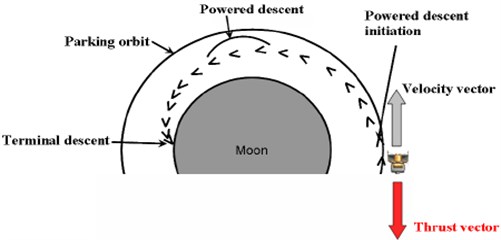
After Earth-Moon transfer, lunar landing spacecraft can descend directly to the surface from the hyperbolic orbit, or the vehicle can first enter into a parking orbit around the Moon before attempting to descent. Both direct descent and parking orbit trajectories have their advantages and disadvantages. A direct descent trajectory requires fewer maneuvers and typically uses less fuel. One disadvantage, however, is that the Earth departure timing becomes crucial. The departure must be timed so that the vehicle not only transfers to the Moon with high accuracy, but also is in the correct position relative to the landing site at arrival. During a direct descent, there is less time to make adjustments to the orbit or to navigational errors accumulated during the Earth-Moon transfer. On the other hand, the parking orbit trajectory expends extra fuel to enter the parking orbit, but can remain in this orbit until the time of final descent. This allows time to observe landing sites, make adjustments to the orbit, perform scientific experiments, etc. The motion of the vehicle can also be observed for a longer duration of time to assess navigational error accumulation. As shown in Fig. 1 a descent from a lunar parking orbit was selected due to safety, reliability, and flexibility for this approach. The lunar descent scheme takes a horizontally oriented spacecraft from orbital speeds at a point of hundreds of kilometers from the desired landing point to an almost vertical orientation and very low speed. Before it starts the powered descent, the orientation of velocity vector remains parallel to the local horizontal vector, means that, at the initiation of powered descending phase, velocity vector pitch angle is 90° with respect to the local vertical axis. With the help of proposed advanced descent scheme, to be discussed in the following sections, this velocity vector pitch angle will be gradually reducing towards zero during powered descent phase of lunar landing spacecraft. Consequently, at the initiation of terminal descent, velocity vector pitch angle of the lunar landing vehicle will be almost zero to ensure vertical landing, which will confirm a successful, safe pin-point landing mission.
Fig. 1Typical lunar landing scenario from parking orbit conditions
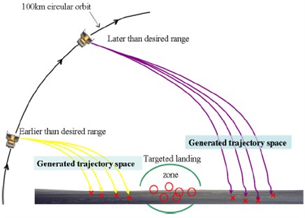
The actual handover conditions from the orbital phase to the descent phase will be initiated close to the horizontal span and vertical range values of the desired landing site. Solution can be like that the final velocity vector pitch angle and reasonable thrust will be specified to generate a trajectory space. A desirable trajectory can then be selected from the options available. It does offer the best option for merging the handover conditions between the orbital phase termination and the descent-phase initiation in an acceptable manner. Depending on the trajectory design requirements, the trajectory space can be rather limited. Therefore, the initial and final velocity vector pitch angle, the initial and final speeds, and the gravity can also be varied to increase the trajectory space. This can be automated into an algorithm that computes a matrix of available trajectory spaces and then selects the most desirable trajectory based on some user-defined criteria. Because this targeting algorithm is not iterative in nature, no risk of divergence exists in creating this trajectory space. However, the spacecraft may be at a distance that is too far from or too close to the targeted location for a safe landing, meaning that a desirable trajectory is not available. If the spacecraft is too far from the targeted landing site, the real-time guidance algorithm would wait. If the spacecraft is too close, the decision should be made to wait another orbit for the descent initiation, as shown in Fig. 2.
Fig. 2Trajectory adjustment and search for a precise landing path
The lunar guidance scheme takes a horizontally oriented spacecraft from orbital speeds at a point of hundreds of kilometers from the desired landing point to an almost vertical orientation and very low speed. Implemented guidance schemes for lunar landing date back to the Apollo era [1, 21]. Although the Apollo lunar descent guidance schemes worked well to meet the criteria of the 1960s, they can not fulfill the goal of lunar exploration that encompasses the desire to easily and cheaply explore many locations on the moon.
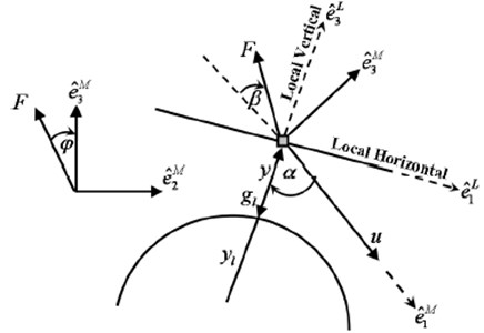
Fig. 3Schematic diagram of lunar descent
3. 3-dimensional motion equation of lunar lander
A schematic diagram of lunar descent is described in Fig. 3. Local vertical and local horizontal (LVLH) reference frame is denoted by . It also shows the relationship of the maneuver frame denoted by to the LVLH unit vectors. Fundamental three dimensional equations of motion to describe the spacecraft proposition concerning a uniform sphere-shaped lunar body [3] are divided into two parts. One is the equations of spacecraft motion for dynamic states as follow:
where is spacecraft velocity vector magnitude or spacecraft speed, is lunar gravitational acceleration, is ratio of thrust and vehicle mass , is pitch angle of the vehicle velocity vector relative to the local vertical, is angle of thrust vector relative to reverse direction of spacecraft velocity, is altitude of the spacecraft from lunar surface, is lunar radius, is cross range angle, and is thrust roll angle.
The remaining part to describe the fundamental equations of motion for kinematics states are:
where and are the horizontal span and cross range distance, respectively.
3.1. Preliminary postulation
Right hand sides of the spacecraft governing equations are reduced to function of velocity vector pitch angle . For this purpose some reasonable assumptions are made regarding thrust to mass ratio, thrust vector angle and lunar gravitational acceleration force. With the aim of developing an analytical solution, a constant thrust-to-mass ratio is considered. To generate an ideal descent trajectory it is rational to assume a constant value for i.e., and , and control input is set to zero. But in the situation of constant thrust acceleration, will not be constant and so will vary. Yet, this error will be removed by the real time guidance algorithm. Therefore, using initial values for mass and gravity is a straightforward assumption for this solution. The changes are observed bellow:
Therefore, is constant. Here we can take some assumption at the face of reference trajectory generation. It is reasonable to assume that in order that 1. Then the equation for down range and cross range become:
4. 3-dimensional inclusive numerical solution
To find the full integrated numerical solutions for speed , time , downrange , altitude and cross range as a function of velocity vector pitch angle during power descend phase; authors have performed the following mathematical derivations for simplification. Therefore, the equation for speed is derived with the help of Eq. (7) and Eq. (8):
Then:
This can be integrated as:
Then following equation can be obtained:
Therefore, the equation for speed:
where the Lambert function is expressed as [22]:
Now the inclusive numerical resolution for descent time, as a function of velocity vector pitch angle, can be obtained by integrating the following equation developed by Eq. (8) and Eq. (12):
Again, for vertical range and horizontal flight path distance, it can be written that:
Now substituting the values from Eq. (4):
where can be replaced from Eq. (13). For the solution of horizontal span as a function of velocity vector pitch angle , the same procedure can be followed:
From Eq. (10):
and similar procedure is applied for the derivation of cross range:
5. 3-dimensional conventional descent
Analytical solution for lunar descent is obtained here by assuming the lunar surface as a plane surface so that the lunar radius is . Therefore, the Eq. (7) now reduces to:
This reduced equation is used to obtain a single, distinguishable differential equation with as the self-regulating variable. From the above we have:
then:
At this time, Eq. (23) can be integrated to find the descent speed as a function of velocity vector pitch angle [11, 18]:
Differentiating Eq. (24):
Using the above value of the speed , we can obtain the solution for time, altitude, down range and cross range. First, the descent time is given as:
Using Eq. (8) and Eq. (25) gives:
Similarly, the altitude is given as:
Using Eq. (4), Eq. (21) and Eq. (25) gives:
Using Eq. (10) and Eq. (21), the down range distance is given as:
Using Eq. (25) gives:
Similarly, using Eq. (11) and Eq. (21), the cross range distance is given as:
Using Eq. (25) gives:
5.1. Descent constraints
Along with the assumptions described in Section 3.1, other required descent specifications are considered to integrate the developed equations and to compare the simulation results between 3-dimensional numerical and analytical solutions for lunar descent scheme. Specific descent speculations are shown in Table 1.
Table 1Lunar descent specifications
Item | Value |
Lunar gravitational acceleration () | 1.623 [m/s2] |
Thrust to mass ratio () | 4 [N/kg] |
Initial lander speed () | 1688 [m/s] |
Initial velocity vector pitch angle () | 90 [deg.] |
Initial altitude for powered descent | 100 [km] |
6. 3-dimensional advanced descent solution
To solve the same governing equations for the proposed 3-dimensional advanced scheme, it is again necessary that the right hand sides of the equations are kept as a function of velocity vector pitch angle . New assumption of centrifugal acceleration term is considered for homogeneous spherical lunar surface. Assumptions for mass and lunar gravity are identical to the Section 3.1. But for centrifugal acceleration term, a constant value can be logically chosen which is defined as the ratio between centrifugal acceleration and lunar gravitational acceleration. Though this is noticeably a varying value, during reference trajectory generation phase it is reasonable to consider as an assumption at the initial stage because the real-time guidance will compensate for the errors between the model and the environment. Therefore:
With these assumptions and making consistent with the traditional lunar descent works, speed can be recognized by following differential equations formulating as a function of velocity vector pitch angle :
This Eq. (37) can now be directly integrated to obtain the descent velocity as a function of the velocity vector pitch angle :
If:
then:
so:
Assume:
where 0, so that:
where is a measure of the centrifugal acceleration term. Then, the solution for current speed obtains the shape:
Next, the time to go , horizontal span and vertical range are resolved in a manner identical to the conventional lunar descent solution, as follows:
where:
For altitude:
where:
For downrange:
where:
For cross range:
where:
It is evoked that the is the measure of the relation between centrifugal acceleration and lunar gravitational acceleration terms. With the purpose of integration for above equations in a qualitative manner the value for must be an integer. This entails 1, 2,… instead of this solution, directly the ratio , which is mentioned earlier, can be chosen some fractional values to make an integer. But the authors found better results having directly the integer logical values to get a qualitative integration of these equations. Choosing alogical value directly for the proves more preciseness in approximation as well. The influences of differing the constant is demonstrated in previous work [20]. Unlike values (1, 2,...) for are employed into Eq. (42), Eq. (44), Eq. (47), Eq. (50) and Eq. (53) and these equations are numerically integrated withconstant approximate values for and whereas 1.623 m/sec2 and 5 N/kg. Initial and final values for the velocity vector pitch angle is taken 90°and 0° whilethe initial speed is considered as approximate orbital speed, 1688 m/sec. In contrast to this advanced solution, full numerical integrated resolution to Eq. (1)-(2), Eq. (4)-(6), and traditional gravity-turn solutions to Eq. (6) and Eq. (13) are performed for comparison taking same approximation for , , , and as it is made into Eq. (42), Eq. (44), Eq. (47), Eq. (50) and Eq. (53) while no estimation are made about the centrifugal acceleration.
A comprehensive evaluation of this advanced solution with traditional gravity-turn solution, and a numerically integrated solution to the full equations of lunar module descent are exposed in this investigation. It can be noted that varying has reasonable impact on different responses for speed, time, vertical range and horizontal span for lunar descent scheme. The largest impact is observed on the final vertical range variation.
The centrifugal acceleration effectively adjusts the rate of change of the vehicle velocity vector pitch angle which impacts the direction of the velocity vector. Therefore, the term directly influences the vertical range of the trajectory. From the assessment of the various values for , a value of 2 emerges to be a realistic number and improves on different responses of advanced solutions for speed, time, vertical range and horizontal span over traditional solutions.
7. Simulation results
It is observed in the previously derived equations that there is no effect of crossing angle, on the equations for speeds, time and altitude. Therefore, different trajectory responses for descent speeds, time and altitude are shown in Fig. 4(a)-(d). It represent the comparison between numerical, conventional and advanced analytical descent illumination given 2 to the fully integrated solutions to Eq. (1)-(2), Eq. (4)-(5) where 0. The fully integrated solution assumes a constant lunar gravitational acceleration, , and constant thrust to mass ratio, , but does not guess a constant centrifugal acceleration. The computer simulation results for full integrated solution is considered as an ideal measure of lunar descent trajectory. But the method is complex and iterative. It needs long time to execute and not suitable for real time application. However, the result of this ideal situation is a model to follow by any type of solution. It is pleasing if it would get responses with a miniature divergence between a new solution and ideal numerical solution and shows better performance than the conventional one. For this purpose an advanced analytical solution is proposed here and compared the responses. In the Fig. 4(a)-(c), speed and time responses are almost similar between numerical, conventional and advanced analytical solution. Great impact is observed for altitude response in Fig. 4(d) which demonstrates the trajectory discrepancy and the guidance will be required to remove.
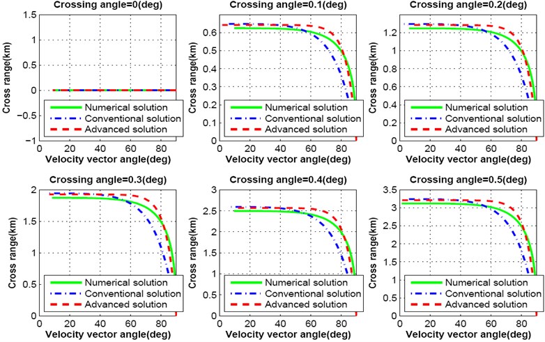
Fig. 5-7 show simulation results for cross range responses of both numerical, conventional and advanced analytical solutions as a function of velocity vector pitch angle. Crossing angle is a major factor for variation of cross range distance. Authors varied the crossing angle intentionally to observe the effect on cross range distance during lunar descent. Lunar landing spacecraft does not travel towards cross range distance while the crossing angle is maintained zero degree. With the variation of crossing angle between zero degree to 25 degree, spacecraft travels more than 150 km far towards cross range as shown in Fig. 5. If the crossing angle is maintained within 5 degree, spacecraft moves with in the range of 32.5 km. Deviation of cross range distance per degree is shown in Fig. 6.
Crossing angle is an important factor for precise lunar landing mission. In previous approaches lunar descent trajectory is designed assuming that the crossing angle is zero. But the simulation results shown in Fig. 7 indicate that, lunar landing spacecraft deviates more than 600 m from the line of down range while crossing angle is changed from zero to 0.1 degree. For 0.5 degree of crossing angle spacecraft moves more than 3 km from the line of down range.
Fig. 4Comparison between numerical solution, convention analytical solution and proposed advanced analytical solution: speed, time and altitude
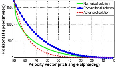
a) Horizontal speed
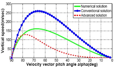
b) Vertical speed
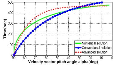
c) Time
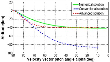
d) Altitude
Fig. 5Cross range response varying crossing angle from 0.0 degree to 25 degree

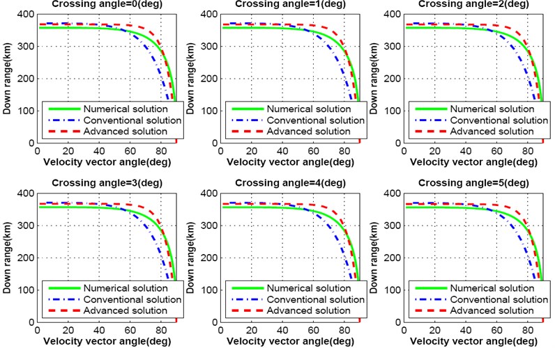
This analysis proves that the crossing angle plays a major role in trajectory design for precise lunar landing mission. Further, only the cross range distance is not affected with the change of crossing angle, it influences the down range distance as well. Fig. 8-9 show the simulation results for down range response of both numerical, conventional and advanced solutions as a function of velocity vector pitch angle. With the increase of crossing angle, down range distance decreases. As a result, lunar landing spacecraft will travel shorter distance than the required. If the crossing angle increases up to 25 degree, down range distance decreases more than 30 km as shown in Fig. 8. The influence on down range due to the change of each degree crossing angle is shown in Fig. 9.
Fig. 6Cross range response varying crossing angle from 0.0 degree to 05 degree
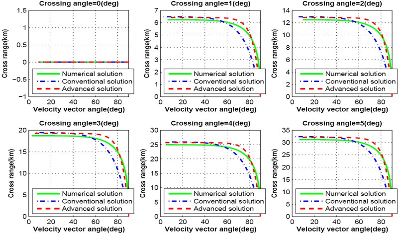
Fig. 7Cross range response varying crossing angle from 0.0 degree to 0.5 degree
It is already mentioned that the advanced solutions are presented to reduce the complexity of numerical solution and to overcome the limitations of conventional scheme. Cross range and down range responses of above simulation results prove that the deviation occurs between numerical conventional and advanced solution. These deviations will influence precise lunar landing mission. Again, advanced solution of lunar descent motion equation is much more suitable for real-time application. Deviation of cross range and down range from ideal solution can be overcome using real-time guidance scheme during descent.
Fig. 8Downrange response varying crossing angle from 0.0 degree to 25 degree
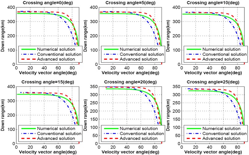
Fig. 9Downrange response varying crossing angle from 0.0 degree to 5 degree
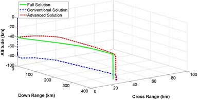
8. 3-dimensional response
Section 4, 5 and 6 described the detail mathematical modeling of 3-dimensional representation of numerical, conventional and advanced descent solution of lunar landing mission. Based on that derivation, computer simulation is performed. Fig. 10(a)-(d) represents a comparison of 3-dimensional trajectory responses for spacecraft descent on lunar surface while the governing equations are solved by complete integration method, conventional illumination and advanced solution scheme. Equations of different states are numerically integrated with the constant values for lunar gravitational acceleration , thrust to mass ratio , initial vehicle speed and initial velocity vector pitch angle mentioned in Table 1. Simulation is categorized for different values of crossing angle between 5 degree to 20 degree with the increment of 5 degree. It is observed that, altitude is not affected at all, while crossing angle is changing. On the other hand, down range and cross range distances are influenced because of different values of crossing angle. Result shows that the trajectory response of less complex advanced solution is always following the response of ideal but complex numerical solution having better performance than the conventional method of solution.
Fig. 103-dimensional flight path comparison between numerical and analytical solution for different crossing angle
a) Crossing angle = 5 degree
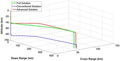
b) Crossing angle = 10 degree
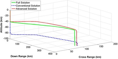
c) Crossing angle = 15 degree
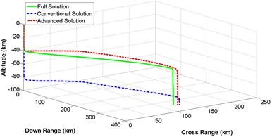
d) Crossing angle = 20 degree
8.1. Execution time analysis
While the on line trajectory generation is a great challenge for lunar or planetary landing, it becomes useful to compare elapsed time analysis that is utilized to solve the numerical calculations at the time of producing trajectory response on-board. Investigations are done observing computing time performance analysis for different schemes using laboratory desktop computer. Here it can be mentioned that Intel dual core processor-speed of laboratory desktop computer is 2.66 GHz, which is 13.33 times higher than the current available on-board computer with only 200 MHz speed. Among different responses of proposed advanced solutions, response for taking 2 is specially observed in this study because this response is much attractive than the traditional scheme. A significantly less required executing time is observed than the fully integrated numerical solution. According to the elapsed time analysis, proposed advanced schemes are quicker than the complete numerical solution.
9. Conclusions
The conventional 2-dimensional lunar descent and landing problem has been advanced to allow an accurate representation of lunar descent from orbital condition. A comprehensive 3-dimensional evaluation of advanced scheme, conventional illumination and numerical solution for lunar landing spacecraft is exposed in this investigation finding a reasonable assumption for lunar surface and centrifugal acceleration, it significantly advanced the sphere of validity of the traditional gravity-turn solution from low velocity terminal descent to a complete descent from orbital situation. The accessibility of the descent velocities, time, vertical range and horizontal span as a function of the velocity vector pitch angle could be utilized to lessen the computational trouble on real-time lunar descent guidance scheme for future landing mission. Moreover, the formulated 3D solution will provide a great advantage in developing complete guidance scheme for pin-point landing mission.
References
-
Cheng R. Lunar Terminal Guidance in Lunar Missions and Exploration. Wiley, New York, 1964, p. 308-355.
-
Cheng R., Meredith C., Conrad D. Design considerations for surveyor guidance. Journal of Spacecraft and Rockets, Vol. 3, Issue 11, 1966, p. 1569-1576.
-
Klumpp R. Apollo guidance, navigation, and control: Apollo lunar-descent guidance. Technical report, MIT Charles Stark Draper Laboratory, 1971.
-
Lutz T. Application of auto-rotation for entry, descent and landing on mars. 7th International Planetary Probe Workshop.
-
Sostaric R. Lunar descent reference trajectory. Technical report, NASA/JSC, 2006.
-
Ueno S., Yamaguchi Y. Near-minimum guidance law of a lunar landing module. 14th IFAC Symposium on Automatic Control in Aerospace, 1998, p. 377-382.
-
Xing-Long L., Gaung-Ren D., Kok-Lay T. Optimal soft landing control for Moon lander. Automatica, Vol. 44, 2008, p. 1097-1103.
-
Kenji U., Yuzo U. S., Shingo N. Tracking control to near-optimal trajectory for a lunar lander. 23rd International Symposium on Space Technology and Science, Vol. 1, 2002, p. 977-982.
-
McInnes C. Gravity-turn descent from low circular orbit conditions. Journal of Guidance Control and Dynamics, Vol. 26, Issue 1, 2003, p. 183-185.
-
Klumpp R. Apollo lunar descent guidance. Automatica, Vol. 10, Issue 2, 1974, p. 133-146.
-
Blackmore L., Acikmese B., Scharf D. Minimum landing-error powered descent guidance for Mars landing using convex optimization. AIAA Journal of Guidance, Control and Dynamics, Vol. 33, Issue 4, 2010, p. 1161-1171.
-
Braun R., Manning R. Mars exploration entry, descent and landing challenges. Journal of Spacecraft and Rockets, Vol. 44, Issue 2, 2007, p. 310-323.
-
Najson F., Mease K. Computationally inexpensive guidance algorithm for fuel-effcient terminal descent. Journal of Guidance, Control and Dynamics, Vol. 29, Issue 4, 2006, p. 955-964.
-
Ackmese B., Polen S. A convex programming approach to constrained powered descent guidance for mars pinpoint landing. AIAA Journal of Guidance, Control and Dynamics, Vol. 30, Issue 5, 2007, p. 1353-1366.
-
Sturm J. A matlab toolbox for optimization over symmetric cones. Optimization Methods and Software, Vol. 11, Issue 1, 1999, p. 625-635.
-
Ye Y. Interior Point Algorithms. Wiley, New York, 1997.
-
Mattingley J., Boyd S. Real-time convex optimization in signal processing. IEEE Signal Processing Magazine, Vol. 3, Issue 11, 2010, p. 1569-1576.
-
Acikmese B., Blackmore L. Lossless convexication for a class of optimal control problems with nonconvex control constraints. Automatica, Vol. 47, Issue 2, 2011, p. 341-347.
-
Steinfeld B., Grant M., Matz D., Braun R., Barton G. Guidance, navigation and control system performance trades for mars pinpoint landing. AIAA Journal of Spacecraft and Rockets, Vol. 47, Issue 1, 2010.
-
Mehedi I., Kubota T. Advanced guidance scheme for lunar descent and landing from orbital speed conditions. Transaction of Japan Society for Aeronautical and Space Sciences, Vol. 54, Issue 184, 2011, p. 98-105.
-
Miele A., Mancuso S. Optimal trajectories for Earth-Moon-Earth flight. Acta Astronautica, Vol. 49, Issue 2, 2001, p. 59-71.
-
Corless R. M., Gonnet G. H., Hare D. E. G., Jeffrey D. J., Knuth D. E. On the Lambert W function. Advances in Computational Mathematics, Vol. 5, 1996, p. 329-359.
-
Sturm J. F. Implementation of interior point methods for mixed semi-definite and second order cone optimization problems. Optimization Methods and Software, Vol. 17, Issue 6, 2002, p. 1105-1154.
-
Topcu U., Casoliva Jordi, Mease K. Minimum-fuel powered descent for mars pinpoint landing. Journal of Spacecraft and Rockets, Vol. 44, Issue 2, 2007, p. 324-331.
About this article

This article was funded by the Center of Excellence in Intelligent Engineering Systems (CEIES), King Abdulaziz University, Jeddah. Therefore, the authors acknowledge with thanks CEIES financial support.
