Abstract
Front and rear suspensions are commonly equipped on bicycles for the purpose of riding comfort especially for mountain bicycle. Suspension system includes damper for shock absorbing and spring for rebounding. Therefore suspension system would increase leg muscle forces for riding bicycle since damper dissipates some energy. ADAMS®/LifeMOD® are proposed in this research to establish a bicycle-human integrated multibody dynamic model to investigate the impact of bicycle suspensions on cyclist’s leg muscle forces under various pedaling conditions and human body vibration for evaluation of riding comfort. Muscles studied include adductor magnus, rectus femoris, vastus lateralis and semitendinosus. Comfort analyses include the vibrating acceleration in vertical direction of lower torso and scapula. Pedaling conditions include riding on flat road, over a road bump, and climbing slope. The results indicate that suspension system increases the pedaling forces of vastus lateralis and semitendinosus. However suspension system decreases the pedaling forces of adductor magnus and rectus femoris. Suspension systems, especially the rear suspension, may effectively reduce human body vibrating acceleration. The integrated model built in this research may be used as reference for designing bicycle suspension systems. Also, the results of this study may be used as a basis of leg weight training to strengthen certain muscles for long-distance off-road cyclists.
1. Introduction
The purpose of installing front/rear suspension systems on a bicycle is to provide the cyclist more comfortable experience when riding on soil and gravel road or other uneven surfaces. To understand the performance of bicycle suspension system Waechter, et al. [1] developed a 2-D lumped-masses dynamic system model to simulate off-road bicycle pedaling. Wang and Hull [2] developed a 2-D multibody model to simulate a cyclist riding suspension bicycle and study the reduction of vibration. Yang [3] suggested the spectral density function of cushion’s acceleration as an index to investigate bicycle riding comfort. Rankin and Neptune [4] analyzed the configuration of bicycle seat, the seat tube angle, and pelvic orientation to obtain the maximum crank power. Kooijman, et al. [5] installed several sensors on an experiment bicycle. Data collected from sensors are employed to verify a three dimensional benchmarked bicycle model. The results from experiment and 3-D model were very close when both the speed and frequency are low.
Dynamic analysis software ADAMS® and human body model LifeMOD® are employed in this research to build up a bicycle-human integrated multibody dynamic model for simulating bicycle riding. LifeMOD® and ADAMS® are widely used on human body dynamics study. For example, Lee et al. [6] used the software to analyze impulse force on human body from rifle shooting. Kenny et al. [7] used the software to analyze golf driving. A golfer swing model built by ADAMS/LifeMOD® was conducted by Tucker et al. [8]. Besides, the software extends to the study of the impact force of Taekwondo side kick [9], modeling boat rower [10], and modeling cyclist to explore the leg forces and joint loads [11]. In medical related research, ADAMS/LifeMOD® was used to analyze the spine spacer dynamics of using Dynesys dynamic stabilization system implanted in the vertebra [12], and to dynamically simulate the human thoracolumbar [13]. ADAMS/LifeMOD® has drawn much attention to be an effective tool for dynamic modeling of integration mechanical devices and human body.
Front fork suspension and/or rear suspension system are installed to bicycles for the purpose of riding comfort especially for mountain bicycles. Suspension system includes damper for shock absorbing and spring for rebounding. Therefore suspension system would increases bicycle riding effort since damper dissipates some pedaling energy. In this research a 3-D full suspension bicycle model is built by ADAMS®, and a human body model is built by LifeMOD®. Then the bicycle model and the human model are integrated as a multibody dynamic model. The integrated model is employed to simulate the motion of a cyclist riding bicycle under various pedaling conditions. Pedaling conditions include riding on flat road, over a road bump, and climbing slope. Both the impact of suspension systems on the cyclist’s leg muscle forces and human body vibration for riding comfort are analyzed by using this model.
2. Methods
ADAMS® is a multibody dynamic software developed by MDI (Mechanical Dynamics, Inc.). It can be used for modeling a complex mechanical system as a “virtual machine.” LifeMOD® is a three-dimensional computer model of human body developed by LifeModeler, Inc. This model consists of 19 segments for skeleton; segments are connected by 18 joints (Fig. 1(a)). Dynamic properties, such as mass, mass center, etc., of each segment are automatically determined by scaling the input data of human’s height, weight, and age. LifeMOD® has two types of joints including passive stiffness joints and Hybrid III joints. By using passive joints, users need to input the values of joint stiffness and damping. Also the maximum and minimum rotation angles for each of the passive joint must be input by the users. Then a very large stiffness value is adopted as stops when passive joints reach their rotation limits. Hybrid III joints are simulation of Hybrid III dummy’s joints. If use of Hybrid III joints in LifeMOD®, the degrees of freedom, motion limit, and joint strength are numerically the same as Hybrid III dummy. A detailed set of 118 muscles attached to the bones at anatomical landmarks are included in LifeMOD® human body model. Muscles are modeled by spring-damper complexes (Fig. 1(b)) and muscle forces are calculated consequently. The spring constants and damping coefficients are determined by physiological cross sectional area (pCAS). LifeMOD® contains a database of pCAS values for each muscle and is scaled automatically from input body parameters (height, weight, and age).
Fig. 1LifeMOD® human body model [14]
![LifeMOD® human body model [14]](https://static-01.extrica.com/articles/14931/14931-img1.jpg)
a) Segments and joints
![LifeMOD® human body model [14]](https://static-01.extrica.com/articles/14931/14931-img2.jpg)
b) Muscles system (red lines)
In this research a 23 years old male subject with 176 cm height and 70 kg weight is modeled as the cyclist, and therefore the inertia properties of segments and parameters of muscles of the cyclist model are automatically determined by LifeMOD®. This model has both Hybrid III joints and passive stiffness joints. Hybrid III joints are positioned at neck, torso and arms for the response to the bicycle forces. The passive joints are on the legs for pedaling the bicycle. Joint types and degrees of freedom of motion are listed in Table 1. In order to save the computing load, some joints are set to be fixed. Table 2 shows the parameters of the passive stiffness joints. Large stiffness for joint motion stops is set to be 3E7 N/mm for all passive joints.
Table 1Joint types and parameters
Joint | Type | Degrees of freedom | Type of motion |
Neck (upper and lower) | Hybrid III | 3×2 | bending (/)* and torsion ()* |
Thoracic | Hybrid III | 3 | bending (/) and torsion () |
Lumbar | Hybrid III | 3 | bending (/) and torsion () |
Scapular (right and left) | Hybrid III | 0 (fixed) | |
Shoulder (right and left) | Hybrid III | 2×2 | abduction () and flexion () |
Elbow (right and left) | Hybrid III | 2×2 | flexion () and twist () |
Wrist (right and left) | Hybrid III | 0 (fixed) | |
Hip (right and left) | passive | 2×2 | abduction (), flexion () |
Knee (right and left) | passive | 1×2 | flexion () |
Ankle (right and left) | passive | 1×2 | flexion () |
* With the human model stand, directs front, and are horizontal and vertical respectively. | |||
Table 2Parameters of passive stiffness joints
Joint | Type of motion | Stiffness (N/mm) | Damping (N-s/mm) | Motion limit (+) (degree) | Motion limit (−) (degree) |
Hip (right) | abduction () | 1 | 10 | 5 | 45 |
Hip (right) | flexion () | 1 | 10 | 45 | 80 |
Hip (left) | abduction () | 1 | 10 | 45 | 5 |
Hip (left) | flexion () | 1 | 10 | 45 | 80 |
Knee (right and left) | flexion () | 1 | 10 | 120 | 0 |
Ankle (right and left) | flexion () | 1 | 10 | 30 | 30 |
The cyclist model is then imported into ADAMS® and integrated with a bicycle model. Then adjust the human body model position and joints angles to fit the riding posture (Fig. 2). Hands, hip and feet are linked with bicycle handles, saddle and pedals respectively by using bushing joints. Bushing joints have the same stiffness and damping properties as muscles. Road conditions include flat road, a 15 cm height bump on road, and climbing 10° slope as shown in Fig. 2(a), (b) and (c) respectively.
Fig. 2Bicycle riding on different road conditions
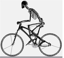
a) Flat road
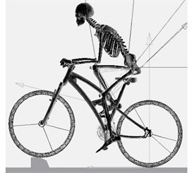
b) Over bump
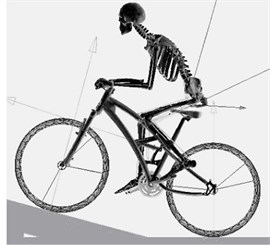
c) Climbing slope
Bicycle model is equipped with front fork suspension and rear suspension as shown in Fig. 3(a) and (b). The spring stiffness and damping coefficient of the front fork suspension are 18 N/mm and 0.6 N·s/mm respectively, and of rear suspension are 36 N/mm and 1.2 N·s/mm respectively.
Fig. 3Bicycle suspension systems
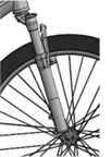
a) front fork suspension
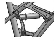
b) rear suspension
After setting up the model, an inverse dynamic simulation of bicycle riding is implemented by ADAMS. During inverse dynamic simulation, a motion driver is equipped at the bicycle crank and makes the bicycle pedaling itself. The leg muscles (spring-damper complexes) contraction histories will be recorded in inverse dynamic simulation. Then the motion driver will be removed and the muscle contraction histories are employed to perform a forward dynamic simulation. Bicycle speed in dynamic analysis is 10 km/h. During forward dynamic simulation, the bicycle will be pedaled by human model to exactly reproduce the motion history recorded in the inverse dynamic simulation, and therefore the human body motion and leg muscle forces would be analyzed by ADAMS. For riding comfort analysis, ADAMS may calculate the acceleration of some specific points on human model for analyzing vibration just like putting accelerometers on to those points. The effectiveness of bicycle suspension systems for riding comfort is evaluated by the vertical acceleration of human body model.
3. Results and discussion
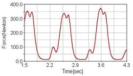
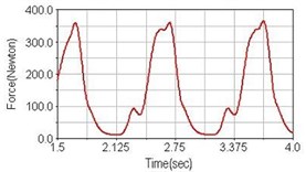
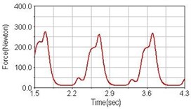
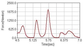
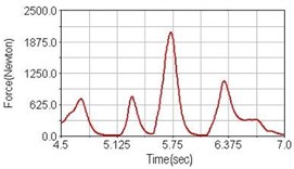
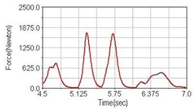
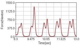
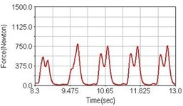
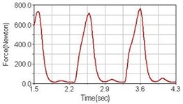
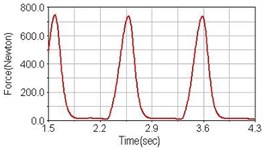
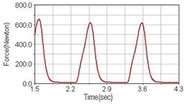
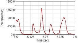
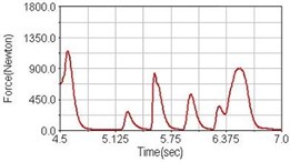
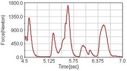
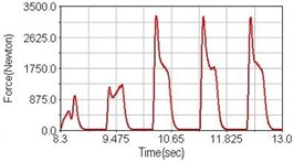
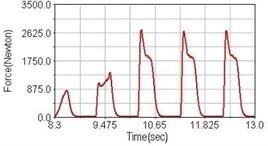
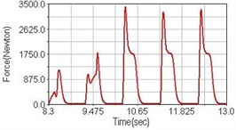
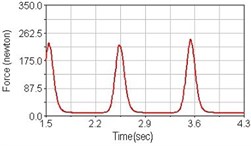
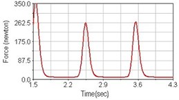
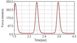
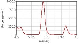
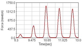
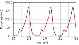
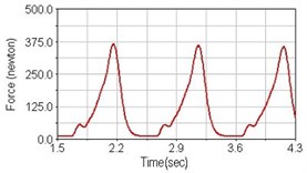
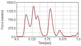
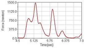
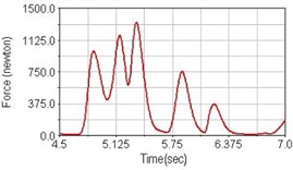
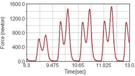
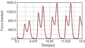
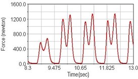
Leg muscle analyzed for the influences of suspension systems include adductor magnus, rectus femoris, vastus lateralis, and semitendinosus. The simulation results show that for climbing slope, suspension systems do not have much influence on pedaling forces as shown in Fig. 6, Fig. 9, Fig. 12 and Fig. 15. For riding on flat road and over bump, both front and rear suspension systems cause increased pedaling forces of vastus lateralis as shown in Fig. 10 and Fig. 11. Also, front suspension causes increased pedaling forces of semitendinosus as shown in Fig. 13 and Fig. 14.
Fig. 4Pedaling forces of adductor magnus for riding on flat road
a) No suspension
b) Front fork suspension equipped
c) Rear suspension equipped
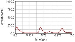
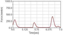
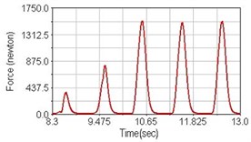
Fig. 5Pedaling forces of adductor magnus for riding over bump
a) No suspension
b) Front fork suspension equipped
c) Rear suspension equipped
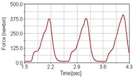
Fig. 6Pedaling forces of adductor magnus for climbing slope
a) No suspension
b) Front fork suspension equipped
c) Rear suspension equipped
Fig. 7Pedaling forces of rectus femoris for riding on flat road
a) No suspension
b) Front fork suspension equipped
c) Rear suspension equipped
Fig. 8Pedaling forces of rectus femoris for riding over bump
a) No suspension
b) Front fork suspension equipped
c) Rear suspension equipped
Fig. 9Pedaling forces of rectus femoris for climbing slope
a) No suspension
b) Front fork suspension equipped
c) Rear suspension equipped
Fig. 10Pedaling forces of vastus lateralis for riding on flat road
a) No suspension
b) Front fork suspension equipped
c) Rear suspension equipped
Fig. 11Pedaling forces of vastus lateralis for riding over bump
a) No suspension
b) Front fork suspension equipped
c) Rear suspension equipped
Fig. 12Pedaling forces of vastus lateralis for climbing slope

a) No suspension
b) Front fork suspension equipped
c) Rear suspension equipped
Fig. 13Pedaling forces of semitendinosus for riding on flat road
a) No suspension
b) Front fork suspension equipped
c) Rear suspension equipped
Fig. 14Pedaling forces of semitendinosus for riding over bump
a) No suspension
b) Front fork suspension equipped
c) Rear suspension equipped
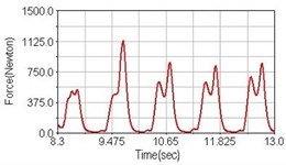
Fig. 15Pedaling forces of semitendinosus for climbing slope
a) No suspension
b) Front fork suspension equipped
c) Rear suspension equipped
Table 3 shows the comparisons of pedaling suspension bicycle with rigid (non-suspension) bicycle. A “+” sign means pedaling force increased, a “–” sign means pedaling force decreased compared with pedaling a rigid bicycle, and “–” indicates no significant difference between pedaling suspension or non-suspension bicycle.
Table 3Comparisons of forces of muscles under various conditions.
Road/suspension | Muscles | ||||
Adductor magnus | Rectus femoris | Vastus lateralis | Semitendlnosus | ||
Flat road | with front suspension | – | – | +20 % | +17 % |
with rear suspension | –23 % | –14 % | +60 % | – | |
Over bump | with front suspension | – | –33 % | +50 % | +14 % |
with rear suspension | –8 % | +26 % | +25 % | – | |
Climbing slope | with front suspension | – | –20 % | – | +7 % |
with rear suspension | – | – | – | −8 % | |
The results also show that climbing a 10° slope needs to pay a lot more pedaling effort compared with riding on flat road as shown in Fig. 4/Fig. 6, Fig. 7/Fig. 9, Fig. 10/Fig. 12, and Fig. 13/Fig. 15.
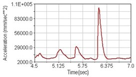
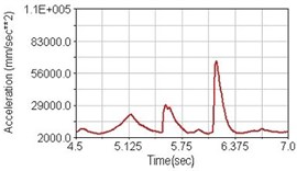
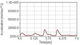
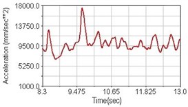
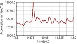
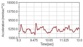
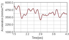
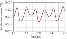
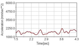
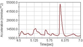
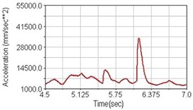
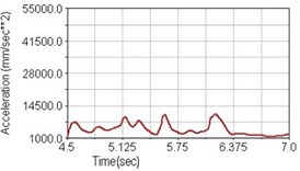
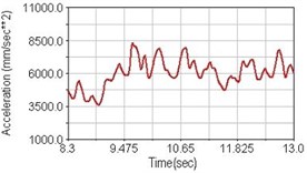
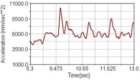
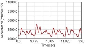
Regarding the riding comfort, a Danish multinational company Bruel & Kjaer specialized on vibration and sound measurement suggests that human body vibration may be evaluated by either acceleration or frequency [15]. Larger maximum peak or root mean square values of vibrating acceleration over a period of time represent less comfort experience. Vertical accelerations of human body analyzed here include lower torso and scapula. Simulation results show that suspension systems, especially the rear suspension, may effectively reduce human body vibrating acceleration under the conditions of riding on flat road and over a bump as shown in Figs. 16, 17 and Figs. 19, 20 respectively. Therefore bicycle suspension systems cause more comfort riding experience. However when climbing slope, front fork suspension causes a larger acceleration peak values as shown in Fig. 18(b) and Fig. 21(b). This phenomenon might be induced by the fact that on climbing slope, larger forces apply on the bicycle and cause larger accelerations.
Fig. 16Vertical acceleration of lower torso for riding on flat road
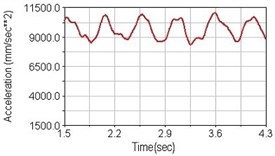
a) No suspension
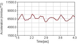
b) Front fork suspension equipped
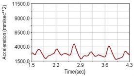
c) Rear suspension equipped
Fig. 17Vertical acceleration of lower torso for riding over bump
a) No suspension
b) Front fork suspension equipped
c) Rear suspension equipped
Fig. 18Vertical acceleration of lower torso for climbing slope
a) No suspension
b) Front fork suspension equipped
c) Rear suspension equipped
Fig. 19Vertical acceleration of scapula for riding on flat road
a) No suspension
b) Front fork suspension equipped
c) Rear suspension equipped
Fig. 20Vertical acceleration of scapula for riding over bump
a) No suspension
b) Front fork suspension equipped
c) Rear suspension equipped
Fig. 21Vertical acceleration of scapula for climbing slope
a) No suspension
b) Front fork suspension equipped
c) Rear suspension equipped
4. Conclusions
Based on this research ADAMS® and LifeMOD® may efficiently and effectively simulate bicycle riding and study the human body dynamics. This study shows the suspension systems give cyclist more comfortable riding experience but increase on pedaling effort for expense. Further work may analyze the effect of bicycle suspension system corresponding to the road unevenness under different cycling speed. The results of this study together with further work will be useful for bicycle suspension system design. The results of this study may be used as a basis of leg weight training to strengthen certain muscles for long-distance off-road cyclists. Also simulation of bicycle riding by using ADAMS®/LifeMOD® may analyze the joint loads of cyclist and therefore to avoid sport injury.
References
-
M. Waechter, F. Riess, N. Zacharias A multibody model for the simulation of bicycle suspension systems. Vehicle System Dynamics, Vol. 37, Issue 1, 2002, p. 3-28.
-
E. L. Wang, M. L. Hull A dynamic system model of an off-road cyclist. Journal of Biomechanical Engineering-Transactions of the ASME, Vol. 119, Issue 3, 1997, p. 248-253.
-
M. H. Yang A study on comfortable effect of a bicycle rider with different dampers. Mechanical Engineering, National Cheng Kung University, Master thesis, 2008.
-
J. W. Rankin, R. R. Neptune The influence of seat configuration on maximal average crank power during pedaling, a simulation study. Journal of Applied Biomechanics, Vol. 26, Issue 4, 2010, p. 493-500.
-
J. D. G. Kooijman, A. L. Schwab, J. P. Meijaard Experimental validation of a model of an uncontrolled bicycle. Multibody System Dynamics, Vol. 19, Issue 1-2, 2008, p. 115-132.
-
Y. S. Lee, Y. J. Choi, K. H. Han, J. W. Chae, E. J. Choi, I. W. Kim A study on the human impulse characteristics with standing shooting posture. Key Engineering Materials – Advances in Fracture and Strength, Vol. 297-300, 2005, p. 2314-2319.
-
I. C. Kenny, E. S. B. Wallace, D. S. R. Otto Validation of a full-body computer simulation of the golf drive for clubs of differing length. The 6th International Conference on the Engineering of Sport, Germany, 2006.
-
C. B. Tucker, I. C. Kenny, R. Anderson Development of a large-scale golfer computer model to study swing kinematics. Procedia Engineering, Vol. 2, 2010, p. 34-39.
-
J. H. Lee, Y. S. Lee, K. H.Han A study on impact analysis of side kick in Taewondo. International Journal of Modern Physics B, Vol. 22, Issue 9-11, 2008, p. 1760-1765.
-
S. Serveto, S. Barré, J. M. Kobus, J. P. Mariot A three-dimensional model of the boat-oars-rower system using ADAMS and LifeMOD commercial software. Proc. IMechE., Vol. 224, 2010, p. 75-88.
-
Y. S. Liu, T. S. Tsay, T.C. Wang Muscles force and joints load simulation of bicycle riding using multibody models. Procedia Engineering, Vol. 13, 2011, p. 81-87.
-
S. M. Kim, I. C. Yang, S. Y. Lee, S. Y. Cho Dynamic simulation of universal spacer in Dynesys dynamic stabilization system for human vertebra. Transactions of Nonferrous Metals Society of China, Vol. 19, 2009, p. 238-242.
-
K. T. Huynh, I. Gibson, W. F. Lu, B. N. Jagdish Simulating dynamics of thoracolumbar spine derived from LifeMOD under haptic forces. World Academy of Science, Engineering and Technology, Vol. 64, 2010, p. 278-285.
-
http://www.lifemodeler.com/LM_Manual/modeling_segments.shtml, 2013.
-
http://doks.khbo.be/doks/do/files/FiSe8a8199820e31b83d010e65f7d7f20230/Human%2520Vibration%2520-%2520ba7054.pdf
About this article

