Abstract
Instead of using the traditional periodical diagnostics, modern technological machinery has increasingly been using monitoring systems based on acceleration transducers of mechanical vibrations. Although, oftentimes it is difficult to identify rolling bearing faults, even if constantly monitoring and analyzing the machinery vibration acceleration or vibration velocity FFT spectra or their cascades. We usually run into such problems when analyzing gravity based technological processes (separators, diffusion machinery) in vertical machinery observations. This is because the angular position of imbalance mass varies often in this type of machinery, which causes the inner ring race fault in the bearing. This article describes the comparative experimental research data between the vertical and horizontal axis rotors. The test rig consists of the disk fixed onto the end of the shaft; the deep groove rolling bearing 6004-2Z/C3 with inner ring race defect is mounted behind the support. Throughout the experiment tests, the angular position of imbalance mass and inner ring race local defect is switched from 00 to 3600, each 450 angular step value. The study is carried out both with rotor axis oriented vertically and horizontally. In order to simplify the data being analyzed and to quantifiably assess the diagnostic experiments of vertical and horizontal rotor defects, statistical processing parameter called “Defect Visibility Ratio” (DVR) is being designed. Through the use of this statistical parameter, the defect-detection capabilities of rotor with bearing inner ring race fault can be determined quantifiably.
1. Introduction
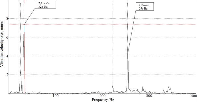
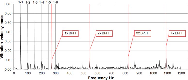
Thanks to numeric and parametric optimization, modern technological equipments are much more efficient than these were 20-30 years ago. Due to digital controlling methods, technological processes can be controlled much more accurately. However, constantly increasing the efficiency of technological equipment, it can become unsafe to operate if adequate vibration monitoring and diagnostics systems are not installed and the dynamics of monitored system and typical defect indicators of rotor are not analyzed properly. The basic principles of rotor machinery diagnostics and the associated monitoring systems are outdated. The only areas that have improved so far are their technical development, data transfer rates and the capabilities of data processing. It is very difficult to identify certain defects of rotor rolling bearings, even with periodical diagnostics of technological equipment and its constant monitoring. This is due to some of the specifics of the technological equipment. This particular article is focusing on vertical and horizontal rotating machinery, the imbalance mass of rotors can change position due to technological processing operations carried out. The purpose of this work is to determine and quantifiably assess the variation of the rolling bearing inner ring defect visibility in FFT vibration acceleration spectra, when the excitation force of imbalance mass and the angular position of the rolling bearing inner ring race defect location changes in vertical and horizontal rotor. The vertical axis centrifuge is shown in Fig. 1. The FFT spectrums of centrifuge for different working conditions are shown Fig. 2 and Fig. 3. We can observe that the value of synchronous frequency, measured on rolling bearing 3, increases about 3 %, while the value of 1xBPFI increases about 5 %. This can mean that the excitation mass of imbalance force might have the different angular position.
Fig. 1The vertical axis centrifuge
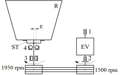
Fig. 2FFT spectrum of vertical centrifuge
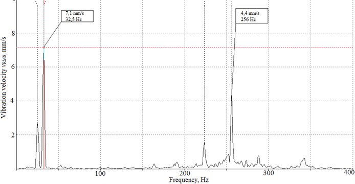
Fig. 3FFT spectrum of vertical centrifuge
Vibration signal analysis is one of the most popular diagnostic and condition monitoring techniques for machinery and technological equipment [1, 2]. Many diagnostic tests are based on the original mechanical oscillation signal analysis (time plots or frequency signal analysis), although there are monitoring and diagnostic methods that are based on amplitude modulation and other processed signal analysis principles [3, 4]. Rolling bearing defects are one of the most USUAL rotor system defects, though, other popular faults are nonetheless important. There are many studies for various types of bearing defects identification, through the use of different diagnostic techniques [5-8]. The methods of roller bearing defect diagnostics are evolving, as evolving the technical possibilities of research equipment, the rolling bearing diagnostics methods are developed using different signal processing filters, envelope spectrum and combined data analysis [9, 10]. Also the diagnostics possibilities of rolling bearings can be expanded using artificial neural networks, SVM and other diagnostics and signal processing methods [11-16]. However, the diagnostic tests In Situ do not give much benefit, since most of these experiments are carried out in laboratories with the experimental stands and usually takes bearing one defect into consideration, while other parts of the rotary system are precisely accurately. In practice, the machinery is like a living organism that has lots of knots whose conditions is yet not critical, but not ideal either. Bearing support vibration data include the whole machine as a unified system vibration. Therefore, it is very difficult to distinguish which knot is responsible for one or the other indication of defect.
2. Experimental setup
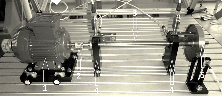
The experimental test rig shown in Fig. 4, consists of rigid frame on which the rotor system is mounted. The rotor system consist of: asynchronous electric motor with current frequency inverter 1, elastic aluminum coupling 2, 20 mm diameter and 600 mm length shaft 3, two supports with SKF 6004/C3 deep groove ball bearings 4 and flywheel disc 5, with holes for imbalance excitation mass fixing.
Fig. 4The experimental test rig
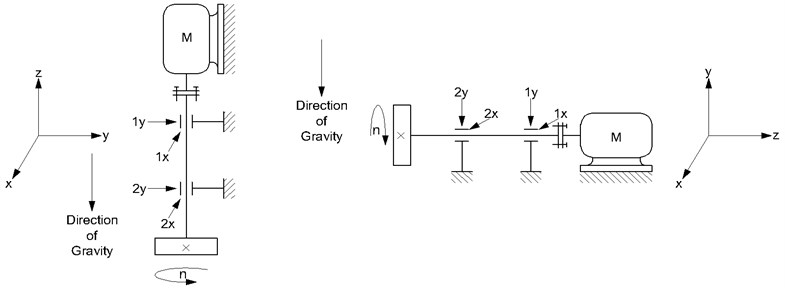
Experimental investigations were carried out with horizontally and vertically oriented rotor rotation axis as shown in Fig. 5.
The mechanical vibrations of rolling bearings supports were measured using acceleration transducers 1x, 1y, 2x and 2y. Measurement directions are shown using in Fig. 5. The signal from acceleration transducers were recorded with multi-channel vibration signal analyzer OROS Mobi-pack OR-36. The data were analyzed using vibration signal processing and analysis software OROS NVGate V8.00. The experimental tests were carried out using deep groove ball bearing, with inner ring race artificially designed fault as shown in Fig. 6(a). This Bearing was mounted in 2nd support of test rig located near the flywheel disk 5. During experimentation, the angle , between the bearing’s inner ring fault position and the imbalance force vector angular position, was changed from 0° to 360° using 45° angular steps. The scheme of the angle evaluation is shown in Fig. 6(b). The experimentation was carried out using three values of imbalance on flywheel: 100 g/mm, 160 g/mm and 220 g/mm. The maximum allowable imbalance, according to ISO 1940-1, for machines of such type is 125 g/mm (grade G 6.3).
Fig. 5Orientation of rotation axis of the experimental test rig with specified acceleration transducers measurement directions
The imbalance in rotor system has been increased in order to determine how the magnitude of imbalance contributes to the rolling bearing inner race faults masking effect [8]. The experimental data show the influence of two parameters to detection of inner ring race faults of rolling bearings using FFT spectra: the flywheel imbalance value and imbalance angular position, versus rolling bearing inner ring race defect angular position. The experiment has been carried out with constant rotating speed of 3000 rpm.
Fig. 6Photography of the inner ring race surface artificial defect a) and b) explanation scheme of the angular position of imbalance force vector Fu relative to inner ring race fault location
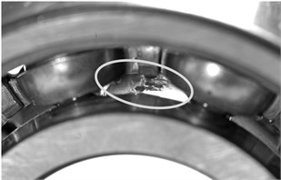
a)
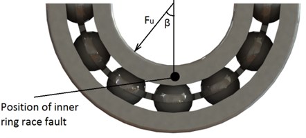
b)
The kinematic frequency, named as BPFI – Ball Pass Frequency Inner, excited of the bearing inner ring race defect and calculated using Eq. (1):
Dimensions of SKF 6004 rolling bearing: 9, number of balls; 50 Hz rotation frequency shaft with inner ring; 7.8 mm ball diameter; 31 mm, pitch diameter; 0° degrees of the contact angle.
3. Overview of experimental results
Synchronous frequencies 50 Hz vibration velocities dominant in FFT spectra of vertical rotor, with 100 g/mm imbalance and angle 0° of imbalance force vector as shown in Fig. 7. Vibration amplitudes of frequencies of 1x BPFI, 2x BPFI, 3x BPFI and 4x BPFI are visible in the FFT vibration velocity spectrum. The 1x50 Hz synchronous frequency vibration velocity amplitude is dominant in the spectra. Higher harmonics as 2x 100 Hz and 3x 150 Hz of rotation speed vibration velocity amplitudes indicated chaotic kinematic motion of the vertical rotor with smaller imbalance and due to higher radial clearance in C3 class rolling bearing.
Fig. 7The vibration velocity spectrum of vertical rotor, with 100 g/mm imbalance value and β= 0° phase angle
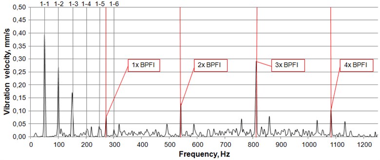
The some asynchronous vibration frequencies harmonics located close to BPFI harmonics can be observed due to vibration velocity amplitude modulation.
The change in angular position of imbalance force vector changes the dominating BPFI harmonics vibration velocities amplitudes. When the position of imbalance force vector moves away from bearing defect location (phase angle increases), dominating BPFI harmonic vibration velocities amplitudes 2x BPFI frequency and higher decreases. The BPFI vibration velocity root mean square value decreases more than two times. This phenomenon complicates diagnostics procedure in early stage of bearing defect indication. The imbalance generated force does not match the rolling bearing inner ring race defect.
Comparing the defect bearing vibration velocity spectra in Fig. 7 and Fig. 8, we observe that changes in angular position of imbalance force vector changed vibration velocity magnitudes of BPFI frequencies vibration velocities amplitudes. Vibration velocity root mean square values significantly decreased however the magnitudes of rotor’s synchronous rotation frequency provide little changes.
Fig. 8The vibration velocity spectrum of vertical rotor, with 100 g/mm imbalance and β= 90° phase angle
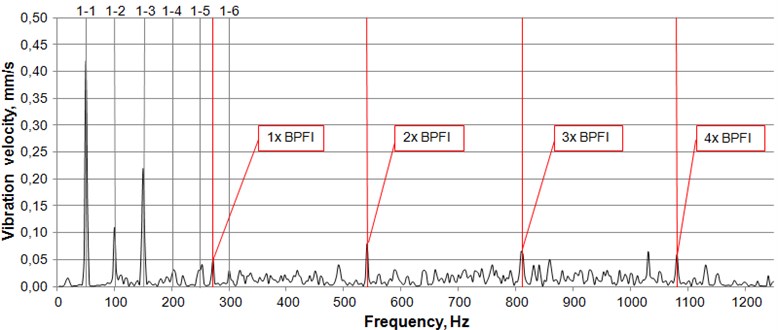
Fig. 9The vibration velocity spectrum of horizontal axis rotor, with 100 g/mm imbalance and β= 90° angle measured by 2x transducer
In order, to simplify the processing procedure of bearing defect diagnostics using vibration measurements experimental data and to make data practically quantifiable and useful, we have designed the statistical parameter “Defect visibility ratio” (). The defect visibility ratio is calculated as the vibration parameter velocity (or acceleration) of dominant bearing defect frequency value (or ) dividing by rotors synchronous rotation frequency 1x vibration value (or ) according Eq. (2):
where: – bearing BPFI dominant defect frequencies harmonics value, mm/s; – 1x rotor synchronous rotation frequency value, mm/s.
Fig. 10The DVR plots versus imbalance values and positions of imbalance force vector phase angles β processed by 2x acceleration transducer
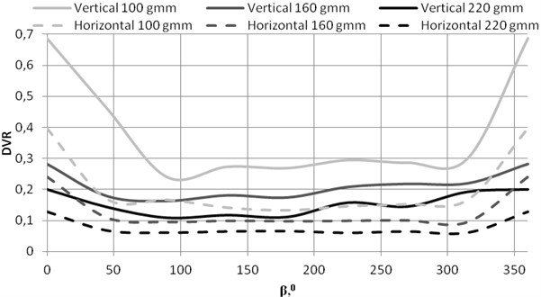
The plots versus imbalance values and positions of imbalance force vector phase angle of experimental tests processed by 2x and 2y acceleration transducers SIGNALS are shown in Fig. 10 and Fig. 11. The values changes in vide range from 0.1 up to 0.7 in vertical axis rotors. In horizontal axis rotors valuable changes measured in 2x transducer direction (horizontal plane) in comparison with 2y transducer direction (vertical plane), Fig. 9. Vertical axis rotors provide higher values independent of the imbalance values and phase angles in comparison with horizontal axis rotors. Vertical axis rotor with damaged bearings inner ring is more sensitive to imbalance vector vary and has higher values, Fig. 12. Rotor generates higher vibration velocities amplitudes of dominant BEARING inner race defect frequency values, because dynamic stiffness of vertical rotor is less in comparison with horizontal axis rotor.
Fig. 11The DVR plots versus imbalance values and positions of imbalance force vector phase angles β of experimental tests processed by 2y acceleration transducer
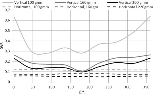
Fig. 12The vertical and horizontal rotor’s DVR plots versus the rotor imbalance with bearing inner ring race defect
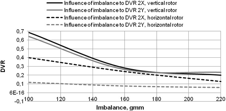
values of vertical rotor are significant when the rotor imbalance is in permissible range according to ISO 1940-1 requirements and dependent on phase angle .
4. Conclusions
1) The vertical axis rotors are more sensitive to imbalance values in comparison with horizontal axis rotors.
2) The identification of bearings inner ring defect using BPFI frequency in practical diagnostics is more informative in vertical axis rotors.
3) The bearing’s defect identification in horizontal rotor with acceleration transducer measuring absolute vibration in direction of gravity force is not informative.
4) The of vertical axis rotor decreases valuable by magnifying imbalance force and bearing defect diagnostics of vertical rotor is more applicable in practice because the is greater in comparison with horizontal axis rotors.
References
-
Linfeng Deng, Rongzhen Zhao A vibration analysis method based on hybrid techniques and its application to rotating machinery. Measurement, Vol. 46, 2013, p. 3671-3682.
-
Diego Fernįndez-Francos, David Martķnez-Rego, Oscar Fontenla-Romero, Amparo Alonso-Betanzos Automatic bearing fault diagnosis based on one-class v-SVM. Computers & Industrial Engineering, Vol. 64, Issue 2013, p. 357-365.
-
Renata Klein, Eyal Masad, Eduard Rudyk, Itai Winkler Bearing diagnostics using image processing methods. Mechanical Systems and Signal Processing,
-
http://www.sciencedirect.com/science/article/pii/S0888327013005128.
-
Adam Docekal, Radislav Smid, Marcel Kreidl, Pavel Krpata Detecting dominant resonant modes of rolling bearing faults using the niching genetic algorithm. Mechanical Systems and Signal Processing, Vol. 25, 2011, p. 2559-2572.
-
Yu Guo, Ting-Wei Liu, Jing Na, Rong-Fong Fung Envelope order tracking for fault detection in rolling element bearings. Journal of Sound and Vibration, Vol. 331, 2012, p. 5644-5654.
-
Borghesani P., Pennacchi P., Randall R. B., RicciR. Order tracking for discrete - random separation in variable speed conditions. Mechanical Systems and Signal Processing, Vol. 30, 2012, p. 1-22.
-
Patel V. N., Tandon N., PandeyR. K. Vibration studies of dynamically loaded deep groove ball bearings in presence of local defects on races. Procedia Engineering, Vol. 64, 2013, p. 1582-1591.
-
Ho D., RandallR. B. Optimization of bearing diagnostic techniques using simulated and actual bearing fault signals. Mechanical Systems and Signal Processing, Vol. 14, Issue 5, 2000, p. 763-788.
-
Ming Y., Chen J., Dong G. Weak fault feature extraction of rolling bearing based on cyclic Wiener filter and envelope spectrum. Mechanical Systems and Signal Processing, Vol. 25, 2011, p. 1773-1785.
-
Sawalhi N., Randall R. B., Endo H. The enhancement of fault detection and diagnosis in rolling element bearings using minimum entropy deconvolution combined with spectral kurtosis. Mechanical Systems and Signal Processing, Vol. 21, 2007, p. 2616-2633.
-
Wang H., ChenP. Intelligent diagnosis method for rolling element bearing faults using possibility theory and neural network. Computers & Industrial Engineering, Vol. 60, 2011, p. 511-518.
-
Samanta B., Al-Balushi K. R. Artificial neural network based fault diagnostics of rolling element bearings using time – domain features. Mechanical Systems and Signal Processing, Vol. 17, Issue 2, 2003, p. 317-328.
-
Bordoloi D. J., TiwariR. Optimum multi-fault classification of gears with integration of evolutionary and SVM algorithms. Mechanism and Machine Theory, Vol. 73, 2014, p. 49-60.
-
Docekal A., Smid R., Kreidl M., KrpataP. Detecting dominant resonant modes of rolling bearing faults using the niching genetic algorithm. Mechanical Systems and Signal Processing, Vol. 25, 2011, p. 2559-2572.
-
Zhang Y., RandallR. B. Rolling element bearing fault diagnosis based on the combination of genetic algorithms and fast kurtogram. Mechanical Systems and Signal Processing, Vol. 23, 2009, p. 1509-1517.
About this article

