Abstract
Vibrations of non-homogeneous tapered parallelogram plate with mixed boundary conditions are investigated. Tapering of plate is specified exponentially in one direction while the behaviour of non-homogeneity is considered with parabolic variation in density. Theoretical analysis of bi-parabolic temperature variation is presented. The developed approach is based on classical plate theory and plate geometry is approximated by skew coordinates. Effect of mixed boundary conditions on first two modes of natural frequencies of vibration of parallelogram plate are discussed for various values of plate parameters such as thermal gradient, aspect ratio, skew angle, taper constant and non-homogeneity constant. Results are shown in graphical manner.
1. Introduction
Using plates of variable thickness mainly in aerospace industry, bridges, submarine etc. is a very frequent engineering situation due to operational reasons imposed on the structures such as their light weight, low cost, good strength and high temperature performance characteristics etc. Due to feasibility of boundary conditions and relatively expensive and time consuming experimental set up, it becomes necessary for design engineers to get information about vibrational behaviour of plates for various values of plate parameters. Thus, efficient determination of vibrational frequencies of such kind of plates is fundamental in their designs and performance evaluations.
A lot of work [1-11] has been carried out in the field of vibrations of plates in last few decades. Khanna and Sharma [12] studied natural vibration of visco-elastic plate of varying thickness with thermal effect. Recently, Khanna and Kaur [13, 14] studied effect of non-homogeneity and thermal gradient on natural frequencies of rectangular plate with varying thickness. Khanna and Arora [15] discussed effect of sinusoidal thickness variation on vibrations of non-homogeneous parallelogram plate with bi-linearly temperature variations. Korobko and Chernyaev [16] determined maximum deflection in transverse bending of parallelogram plates. Alijani and Amabili [17] discussed nonlinear vibrations of imperfect rectangular plates with free edges. Rao and Rao [18] presented study on vibrations of elastically restrained circular plates resting on winkler foundation.
The objective of the present study is to analyze the effect of different combinations of boundary conditions on vibration of parallelogram plate under bi-parabolic temperature variation. Authors discussed the vibrational behaviour of parallelogram plate under six boundary conditions i.e. CCCC, SCSC, CCCS, SSSC, CSCS and SSSS where C and S represent clamped and simply supported boundary condition respectively. Authors calculated first two modes of natural frequency of parallelogram plate at various values of plate parameters for all six boundary conditions.
2. Geometry of parallelogram plate
Consider a non-homogenous parallelogram plate OABC (Fig. 1) of density , thickness and Poisson ratio () in -plane. Let and be the length and breadth of parallelogram plate respectively. Also, plate is assumed to be skewed at an angle ‘’ with -axis. Edges of parallelogram plate are numbered as shown in Fig. 1. Skew coordinates (, ) are taken in direction of OA and OC respectively.
Fig. 1A parallelogram plate with skew coordinates (x, y), rectangular coordinates (X, Y) and skew angle (θ)
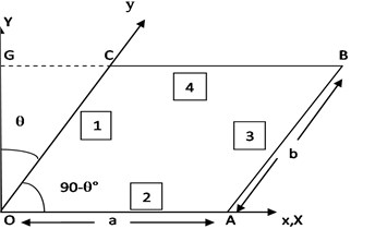
With the help of Fig. 1, rectangular coordinates (, ) can be expressed in terms of skew coordinates (, ) and skew angle () [5]:
3. Fourth order differential equation of motion
Differential equation of motion of parallelogram plate of variable thickness is [2]:
where, is deflection function; is modulus of elasticity and is flexural rigidity of parallelogram plate. Here, ‘’ followed by the suffix denotes partial differentiation with respect to that suffix.
The expressions for kinetic energy () and strain energy ( are [1]:
On using Eq. (1) in Eqs. (3) and (4), maximum kinetic energy () and strain energy ()are obtained as:
4. Assumptions
Since researchers and design engineers always try to know about first few modes of vibration before finalizing any design, authors restricted their study to fulfill their requirements with the following assumptions:
a) Authors assumed that plate is subjected to study bi-parabolic temperature variation [14]:
where denotes the temperature excess above the reference temperature at any point (, ) and denotes the temperature excess above the reference temperature at 0.
Since temperature directly affects the modulus of elasticity (), authors considered as linear function of [14]:
where is the slope of the variation of with
Using Eq. (7) in Eq. (8):
where, (01) is thermal gradient.
b) Thickness variation in parallelogram plate is assumed exponential in -direction as:
here, when 0 and is taper constant i.e. (01).
c) Behaviour of non-homogeneity is assumed with parabolic variation in density in -direction:
Here, at 0 and () is non-homogeneity constant.
Using Eqs. (9)-(11) in Eqs. (5) and (6), one gets modified kinetic energy () and modified strain energy () as:
5. Boundary conditions and corresponding deflection functions
Authors discussed vibration of non-homogeneous parallelogram plate with six boundary conditions i.e. CCCC, SCSC, CCCS, SSSC, CSCS, SSSS on sides 1, 2, 3, 4 (as shown in Fig. 1) respectively. In order to satisfy all above six boundary conditions, deflection function is taken as [11]:
where:
Here, is responsible to hold all six different boundary conditions with the use of four parameters , , and . These parameters (, , , ) can take any two values i.e. 1 (for simply supported boundary condition) and 2 (for clamped boundary condition). Also, is taken for first two modes of frequency with two arbitrary constants and .
6. Methodology
To obtain a frequency equation for parallelogram plate, authors used Rayleigh Ritz method. In Rayleigh Ritz method, the maximum strain energy () must be equal to maximum kinetic energy (). Hence, it is observed that [15]:
Using values of and in Eq. (13), one gets:
where:
and is frequency parameter.
Substituting the value of from Eq. (12) in Eq. (14), an equation involving and is obtained. These two constants ( and ) can be obtained as:
After simplification of Eq. (15), one obtains:
where , (1, 2) involve plate parameters and frequency parameter.
For a non trivial solution of Eq. (16), determinant of the coefficients of Eq. (16) must be zero. Therefore, one gets the frequency equation as:
Eq. (17) is a bi-quadratic equation in . On solving this equation for various values of plate parameters, different values of frequency parameter ( are calculated.
7. Results and discussion
Authors calculated first two modes of frequency for all six boundary conditions. Variations in frequency for both modes of vibration at different values of plate parameters are concisely provided in Figs. 2-13.
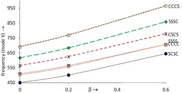
Variations in first and second mode of frequency with increasing taper constant at 0.0, 1.5, 0° are shown in Fig. 2 and Fig. 3 respectively. It is clearly seen that both modes of frequency continuously increase with increasing taper constant for all six boundary conditions.
In Fig. 2, frequency (mode I) is maximum at CCCC boundary condition and minimum at SSSS boundary condition while in Fig. 3, frequency (mode II) is maximum at CCCS and minimum at SCSC boundary condition.
Fig. 2Frequency (mode I) vs. taper constant (θ= 0°, α=0, α1= 0, a/b= 1.5)
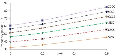
Fig. 3Frequency (mode II) vs. taper constant (θ= 0°, α=0, α1= 0, a/b= 1.5)
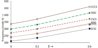
Fig. 4Frequency (mode I) vs. taper constant (θ= 45°, α=0, α1= 0, a/b= 1.5)
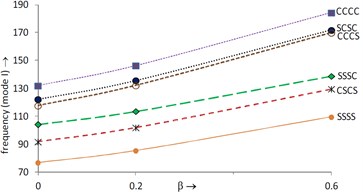
Fig. 5Frequency (mode II) vs. taper constant (θ= 45°, α=0, α1= 0, a/b= 1.5)
For the same values of parameters i.e. 0.0, 1.5 but at 45°, both modes of frequency are plotted in Fig. 4 (mode I) and Fig. 5 (mode II) respectively. Variations of frequency in Figs. 4 and 5 are as same as variations of frequency in Figs. 2 and 3 respectively. It is noted that both modes of frequency increase as increases from 0° to 45°.
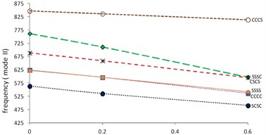
Figs. 6 and 7 show the variations of first and second mode of frequency respectively with increasing thermal gradient at 0.2, 1.5, 45° and 0.0. It is found that both modes of frequency continuously decrease as value of thermal gradient increases. Also, it is evident that frequency (mode I) is maximum at CCCC boundary condition and minimum at SSSS boundary condition in Fig. 6 but second mode of frequency in Fig. 7 is maximum at CCCS boundary condition and minimum at SCSC boundary condition. Further, for the same values of plate parameters i.e. 0.2, 1.5, 45° but increased value of i.e 0.6, frequency for both modes of vibration are shown in Fig. 8 (mode I) and Fig. 9 (mode II). Authors noticed that frequency for both modes of vibration increases as α1 increases from 0.0 to 0.6 for corresponding values of plate parameters. Also, pattern of decreasing frequency lines for first and second mode of frequency in Figs. 8 and 9 is similar to frequency lines in Figs. 6 and 7 respectively for all six boundary conditions.
Fig. 6Frequency (mode I) vs. thermal gradient (α1= 0, β= 0.2, a/b=1.5, θ= 45°)
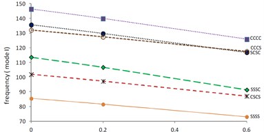
Fig. 7Frequency (mode II) vs. thermal gradient (α1= 0, β= 0.2, a/b=1.5, θ= 45°)
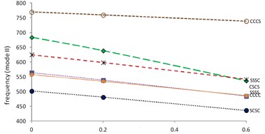
Fig. 8Frequency (mode I) vs. thermal gradient (α1= 0.6, β= 0.2, a/b=1.5, θ= 45°)
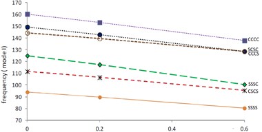
Fig. 9Frequency (mode II) vs. thermal gradient (α1= 0.6, β= 0.2, a/b=1.5, θ= 45°)
Effect of varying aspect ratio on first two modes of frequency at 0.2 for two values of skew angle i.e. 0°, 45° are analyzed for all six boundary conditions and shown in Figs. 10-13.
At 0.2, 0°, first and second mode of frequency with increasing aspect ratio are shown in Figs. 10 and 11 respectively. A continuous increment is noticed in frequency for both modes of vibration as aspect ratio increases from 0.5 to 1.5.
In Fig. 10, frequency (mode I) is maximum at CCCC boundary condition and minimum at SSSS boundary condition. Also, frequencies for SCSC and CSCS boundary conditions are nearly equal at 1.
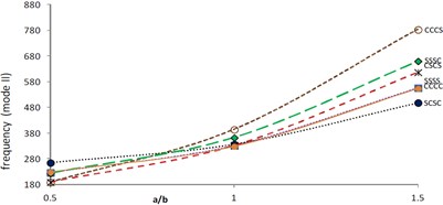
In Fig. 11, frequency (mode II) is maximum at CCCS boundary condition and minimum at SCSC boundary condition at 1.5. Here, it is interesting to note that frequencies for CCCS and CSCS boundary conditions are approximately equal at 0.5.
At 0.2, 45°, frequency is shown in Fig. 12 (mode I) and Fig. 13 (mode II) with increasing values of aspect ratio. Here, behaviour of frequency for both modes of vibration in Figs. 12 and 13 is similar to behaviour of frequency for both modes of vibration in Figs. 10 and 11 respectively. Also, frequency for both modes of vibration increases as increases from 0° to 45° at fixed 0.2.
Fig. 10Frequency (mode I) vs. aspect ratio (θ= 0°, β=α=α1= 0.2)
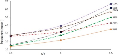
Fig. 11Frequency (mode II) vs. aspect ratio (θ= 0°, β=α=α1= 0.2)
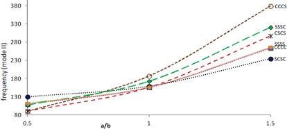
Fig. 12Frequency (mode I) vs. aspect ratio (θ= 45°, β=α=α1= 0.2)
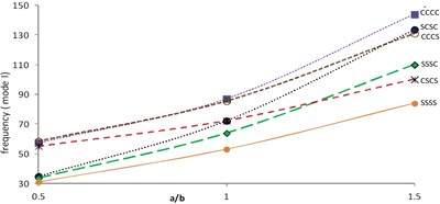
Fig. 13Frequency (mode II) vs. aspect ratio (θ= 45°, β=α=α1= 0.2)
8. Conclusions
Main emphasis of the authors is to provide some information to researchers and scientists about few modes of vibration of parallelogram plate with different boundary conditions. On the behalf of Figs. 2-13, authors conclude the study as follows:
1) Values of both modes of frequency increase as skew angle of the plate increases for all boundary conditions.
2) Frequency for both modes of vibration is more for non-uniform plate i.e. plate of variable thickness (01) as compared to uniform plate i.e. plate of constant thickness ( 0.0).
3) Frequency for both modes of vibration is low for homogeneous parallelogram plate (0.0) as compared to non-homogenous parallelogram plate (01).
4) Consideration of bi-parabolic temperature variations (01) provides low frequency for both modes of vibration as compared to non-thermal effect (0.0).
References
-
Gupta A. K., Kumar Manoj Thermal effect of vibration of a parallelogram plate of bi-direction linearly varying thickness. Applied Mathematics, Vol. 2, Issue 1, 2011, p. 33-38.
-
Gupta A. K., Khanna A. Vibration of visco-elastic rectangular plate with linearly varying thickness vibration in both directions. Journal of Sound and Vibration, Vol. 301, Issue 3-5, 2007, p. 450-457.
-
Leissa A. W. Vibration of plates. NASA SP-160, 1969.
-
Leissa A. W. Recent studies in plate vibration 1981-1985, Part-II complicating effect. The Shock and Vibration Digest, Vol. 19, 1987, p. 10-24.
-
Singh B., Sexena V. Transverse vibration of skew plates with variable thickness. Journal of Sound and Vibration, Vol. 206, Issue 1, 1997, p. 1-13.
-
Huang C. S, Leissa A. W Vibration analysis of rectangular plates with side cracks via the Ritz method. Journal of Sound and Vibration, Vol. 323, Issue 3-5, 2009, p. 974-988.
-
Zhou L., Zheng W. X. Vibration of skew plates by the MLS-Ritz method. Int. J. Mech. Sci., Vol. 50, Issue 7, 2008, p. 1133-1141.
-
Quintana M. V., Nallim L. G. A variational approach to free vibration analysis of shear deformable polygonal plates with variable thickness. Applied Acoustics, Vol. 71, Issue 5, 2010, p. 393-401.
-
Lal Roshan, Dhanpati Effect of non-homogeneity on the vibration of orthotropic rectangular plates of varying thickness resting on a Pasternak foundation. J. Vibration & Acoustics, ASME, Vol. 131, Issue 1, 2009, p. 1-9.
-
Chakarverty S., Petyt M. Natural frequencies for free vibration of non-homogeneous elliptic and circular plate using two dimensional orthogonal polynomials. Appl. Math Modeling, Vol. 21, Issue 7, 1997, p. 399-417.
-
Chakraverty S. Vibration of Plates. CRC Press, Taylor and Francis Group, Boca Raton, London, New York, 2009.
-
Khanna Anupam, Sharma K. Ashish Natural vibration of visco-elastic plate of varying thickness with thermal effect. Journal of Applied Science and Engineering, Vol. 16, Issue 2, 2013, p. 135-140.
-
Khanna Anupam, Kaur Narinder Effect of non-homogeneity on free vibration of visco-elastic rectangular plate with varying structural parameters. Journal of Vibroengineering, Vol. 15, Issue 4, 2013, p. 2146-2155.
-
Khanna Anupam, Kaur Narinder Effect of thermal gradient on natural frequencies of tapered rectangular plate. Int. Journal of Math. Analysis, Vol. 7, Issue 16, 2013, p. 755-761.
-
Khanna Anupam, Arora Pratibha Effect of sinusoidal thickness variation on vibrations of non-homogeneous parallelogram plate with bi-linearly temperature variations. Indian Journal of Science and Technology, Vol. 6, Issue 9, 2013, p. 5228-5234.
-
KorobkoA. V., ChernyaevA. A. Determination of maximum deflection in transverse bending of parallelogram plates using the conformal radiuses ratio. Russian Aeronautics, Vol. 56, Issue 2, 2013, p. 131-134.
-
Alijani F., AmabiliM. Theory and experiments for nonlinear vibrations of imperfect rectangular plates with free edges. Journal of Sound and Vibration, Vol. 332, Issue 14, 2013, p. 3564-3588.
-
Bhaskara L. Rao, Kameswara C. Rao Vibrations of elastically restrained circular plates resting on winkler foundation. Arabian Journal for Science and Engineering, Vol. 38, Issue 11, 2013, p. 3171-3180.
About this article

