Abstract
In order to save energy and materials, some mechanical structures are very thin. Aiming to study the influence of impeller blade thickness on the performance of stainless steel multistage centrifugal pump, the whole flow field of stainless steel multistage centrifugal pump with different blade thickness were calculated based on ANSYS Fluent. The relationship between the impeller blade thickness and the overall performance of the pump was analyzed. To further study the reliability of the impeller structure for stainless steel multistage centrifugal pump, based on the ANSYS Workbench, the final stage impeller of the pump with different blade thickness were calculated by using the finite element method. Results indicate that with the increase of blade thickness, the maximum stress and deformation of the impeller gradually decreased, while the stability of the impeller structure increased.
1. Introduction
It is becoming a world consensus to implement energy-saving and emission reduction because of global energy crisis and soaring atmospheric temperature [1]. Some researchers go on developing new energy sources [2], while others prefer to save energy in existing machinery. As a significant device for energy conversion and fluid transportation, pump is widely used in national economic fields. It is not exaggerated to say that there is an operating pump wherever fluid is flowing [3-5].
Stainless steel multistage centrifugal pump is specially equipped for groundwater extraction in rural areas, factories, mines, water supply companies, geothermal development, and oil fields [1]. It is mainly produced through some advanced procedures including laying-off, stamping, stretching, bulging, shaping, welding, polishing, and etc. [6-8]. Impeller is the key component of stainless steel multistage centrifugal pump, whose blade thickness determined by the steel sheet can reach 0.5 mm. The blade thickness is one of the main parameters in pump design, which makes the traditional design method of casting pump is not fully applicable to stainless steel pump. Although thin blade causes energy-saving effects, it may also influence the reliability of impeller structure. Hence, it has a great realistic significance to study the stress and deformation on impeller with different blade thicknesses.
In the past, some papers studied on the blade thickness in the rotational machinery. C. Sarraf [9] did the experimental study of blade thickness effects on the overall and local performances of a controlled vortex designed axial-flow fan, and the results show the efficiency of the thick blades fan is lower than the efficiency of the fan with thin blades but remains high on a wider flow-rate range, and the mean velocity fields downstream of the rotors are very similar at nominal points with less centrifugation for the thick blades fan. D. Chapple [10] did the effect of impeller and tank geometry on power number for a pitched blade turbine, and the results show that the power number is independent of blade thickness, but dependent on the impeller to tank diameter ratio. C. Galletti [11] did the effect of shaft eccentricity and impeller blade thickness on the vortices features in an unbaffled vessel, and the results show the characteristic frequency of flow instabilities was found to increase with reducing eccentricity or impeller blade thickness. However, few papers studied on the blade thickness in the centrifugal pump.
The strength calculation on impeller of centrifugal pumps is currently based on empirical formulas, but the formulas have simplified greatly the load on impeller. As a result, there are fairly large errors between the calculated value and actual value. With the continuous improvement of computer performance, numerical calculation develops rapidly [12, 13], and Computational Fluid Dynamics has been widely used in the pump design [14-16]. Flow field calculation and strength calculation can be combined through fluid structure interaction (FSI), which makes the results close to actual value. So far most of contemporary studies on FSI of rotating machinery only focus on single stage centrifugal pump [17, 18].
With finite volume method, this study implements flow field calculation on impeller with five different blade thicknesses by ANSYS Fluent and then analyzes the changing law of pump's performance. Based on ANSYS Workbench, this paper studies the final stage impeller of stainless steel multistage pump with FSI and implements finite element calculation on impeller. As a reasonable value of blade thickness, 1.5 mm is selected at last.
2. Solving theory
2.1. Theory on flow field calculation
According to Bernoulli equation, pump experimental head is:
where and are fluid static pressure on outlet and inlet section, and are fluid velocity on outlet and inlet section, and are the distances to base level from outlet and inlet section. The efficiency of pump is the ratio of effective power to shaft power, and is represented by:
where is the effective power, is the shaft power, is volume flow, is the sum torque on shaft, and is angular velocity of impeller. After applying the results of flow field calculation, the pump performance curve is obtained.
2.2. Theory on fluid structure interaction
Fluid solid interaction (FSI) mechanics is the interdisciplinary branch of fluid mechanics science and solid mechanics science. It mainly studies the deformation and movement of solids in the flow field, as well as the impact of this behavior to the flow field. In order to check the impeller strength and predict the exact location of maximum stress on impeller directly, flow field calculation and finite element calculation can be combined together by using FSI.
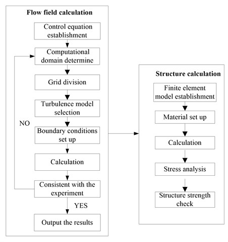
The solving of FSI problems is comprised of two-way coupling and unilateral coupling. The former one means all unknown quantities in both fluid field and solid field are solved at the same time step according to common coupling equations, while the latter is a kind partition iterative solving that means the data is unidirectional when transferring on coupling interface. For inner flow field, the solid deformation influence may be neglected because the deformation of impeller is very small. Thus, unidirectional FSI method is used in this paper and the flow table is shown in Fig. 1.
Fig. 1Computational flow table
3. Modeling
3.1. Hydraulic design of model pump
The stainless steel multistage centrifugal pump of 100XQJ8 is selected in the studies. Its design parameters are listed as below: rated flow 8 m3/h, single stage head 4.5 m, rotational speed 2850 r/min, maximum power 3 kW, and the total head 72 m. In view of the structural condition that the outer diameter of multistage well pump is limited by well diameter, Lu Weigang [19] studied a design method of well pump, the impeller maximal diameter design method, which expands the front shroud of impeller to the edge of pump wall and makes the impeller diameter achieve maximum value while well diameter is invariable.
Impeller with five different blade thicknesses (0.5 mm, 1.0 mm, 1.5 mm, 2.0 mm, and 2.5 mm) are designed as research objects. The geometric parameters are shown in Table 1.
Table 1Geometric parameters of impeller
Geometric parameter | Value |
Blade number | 9 |
Blade inlet angle (°) | 35 |
Blade outlet angle (°) | 23.2 |
Blade wrap angle (°) | 120 |
Front cover plate diameter (mm) | 79.5 |
Inlet diameter of impeller (mm) | 39.4 |
Width of the blade outlet (mm) | 5 |
Slope of impeller outlet (°) | 29.4 |
Shaft diameter (mm) | 12.5 |
External diameter of shaft sleeve (mm) | 17 |
There is an impeller model displayed in Fig. 2(a), whose blade thickness is 1.5 mm. The impeller is in coordination with reverse diffuser, which can shorten the axial length of well pump to the minimum. The main parameters of reverse diffuser are listed as below: the number of blade 8, inlet width 6.2 mm, inlet diameter 75 mm, and outlet diameter 37.5 mm. Reverse diffuser is shown in Fig. 2(b).
Fig. 2Three-dimensional diagram of impeller and reverse diffuser
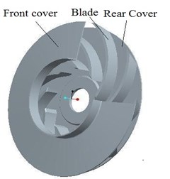
a) Impeller
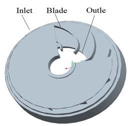
b) Reverse diffuser
3.2. Fluid calculation model
3.2.1. Computational domain
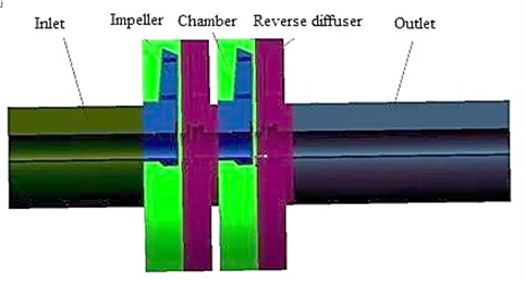
Stainless steel stamping centrifugal pump is one of multi-stage pumps. Compared with single-stage pump, the structure of multi-stage pump is more complex and its flow characteristics are different. Therefore, it’s particularly important to select appropriate series when making numerical simulation for multi-stage pump. I have ever done relevant research. Four different series in a numerical simulation with the blade thickness of 1.5 mm are selected and the efficiency and head at all series are shown in Table 3 and Table 4. As can be seen from Table 3 and Table 4, the efficiency and head of the first-stage in different stages are almost the same. When the series is 2, there is little difference between the second stage and the following, but the difference is big compared with the first stage. It is also consistent with the fact that the flow in the first impeller inlet of multi-stage pump is usually irrotational while rotational in the other impeller inlet. Taking into account that increase of stage will bring about more cell number, thereby demand computer with higher performance, so the two-stage model is selected and the efficiency as well as head of the second stage are taken as performance prediction value. In the numerical calculation of the pump, the water part in the pump is meshed by many small cells. The pump water model is consist of inlet section (water), two impellers (water), two chambers (water), two reverse diffusers (water), outlet section (water), which is shown in Fig. 3.
Table 2Efficiency comparisons of different stages
Series () | 1 | 2 | 3 | 4 |
The first-stage efficiency (%) | 59.51 | 59.93 | 59.79 | 59.86 |
The second-stage efficiency (%) | 62.50 | 62.53 | 62.53 | |
The third-stage efficiency (%) | 62.59 | 62.58 | ||
The fourth-stage efficiency (%) | 62.61 | |||
The total efficiency (%) | 56.57 | 59.55 | 60.12 | 60.14 |
Table 3Head comparisons of different stages
Series () | 1 | 2 | 3 | 4 |
The first-stage head (m) | 4.745 | 4.762 | 4.758 | 4.755 |
The second-stage head (m) | 4.611 | 4.605 | 4.612 | |
The third-stage head (m) | 4.608 | 4.621 | ||
The fourth-stage head (m) | 4.628 | |||
The average head (m) | 4.511 | 4.588 | 4.595 | 4.597 |
Fig. 3Pump water model
3.2.2. Model mesh
In order to verify the quantity of cell affecting the computational accuracy, the experiment of cell independence is done. In theory, with the increase of the cell number, the solution caused by the cell will be gradually reduced until it disappears. But the more the cell number, the slower the computing speed, thus considering the configuration of the computer and the computing time, cell number can not be too much. For the above hydraulic model with the blade thickness of 1.5 mm, five different cell sizes of numerical calculation are selected; the results are shown in Table 4. As can be seen from Table 4, when the cell size is large, the efficiency and single head at rated point (8 m3/h) are relatively small. If the cell size is less than 1.2 mm, with the decrease of cell size, the efficiency and single head almost remain invariable. Taking into account the coordination of computing time and accuracy, 1.2 mm of cell size meets the requirements, so the cell size in this paper is 1.2 mm. Also the detailed information of cell distribution is given as shown in Table 5. In order to verify the quality of the model mesh, the mesh of impeller and reverse diffuser are shown in Table 5.
Table 4Mesh independent analysis
Parameters | Cell size (mm) | ||||
1.0 | 1.2 | 1.4 | 1.6 | 1.8 | |
Cell number | 1912342 | 1176683 | 802300 | 563413 | 418491 |
Efficiency (%) | 62.49 | 62.50 | 62.53 | 61.97 | 61.72 |
Single head (m) | 4.612 | 4.611 | 4.605 | 4.551 | 4.483 |
Table 5Detailed information of grid distribution
Component | Grid number |
Inlet section | 139083 |
First impeller | 96007 |
First chamber | 140078 |
First reverse diffuser | 180234 |
Second impeller | 96007 |
Second chamber | 140078 |
Second reverse diffuser | 180234 |
Out section | 204962 |
Total water model | 1176683 |
3.2.3. Select of turbulent model
Aiming at the turbulent model problem, five different turbulent models of Standard , RNG , Realizable , Standard and SST are used relatively in the numerical calculation of the pump with the blade thickness of 1.5 mm, which is shown in Table 6. According to the Table 5, it is conducted that the efficiency and the single-head by using the Standard are more close to the experimental values, so the Standard is selected in this paper.
Table 6Comparison of different turbulent model
Parameters | Turbulent model | Experimental values | ||||
Standard | RNG | Realizable | Standard | SST | ||
Efficiency / % | 62.50 | 63.14 | 64.57 | 65.28 | 65.83 | 61.36 |
Single-head H/m | 4.61 | 4.52 | 4.98 | 5.07 | 5.16 | 4.75 |
3.2.4. Control equations
Control equations include the continuity equation, momentum equation, energy equation, equation, equation. For steady flow, the general form of equations is as follow:
where – diffusion coefficient; – source term; – independent variable, when take different values, Eq. (3) will have different means of expression.
3.2.5. Test rig setup
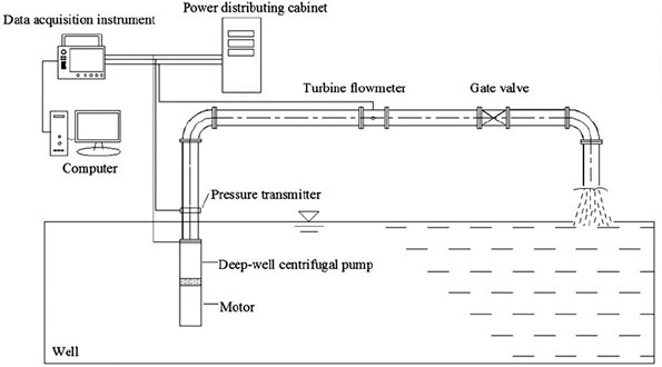
Experiments were done in an open-type pump system, which have the identification from Jiangsu Province of China. The test rig is composed of two parts, namely, the data acquisition system and the water circulation system. The data acquisition system changes all kinds of physical quantities at different conditions, while the water circulation system supplies the necessary environment for centrifugal pump operation. The test rig is shown in Fig. 4. A turbine flowmeter was used to measure the flow and the precision of turbine flowmeter is ±0.3 %. Speed is measured by a tachometer (PROVA RM-1500, Taiwan). During the experiment, only one dynamic pressure transmitters (CYG1401) was used to measure the outlet pressure. The precision of CYG1401 is ±0.2 %.
Fig. 4Test ring of multistage well pump
3.2.6. Experimental results
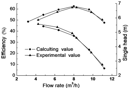
Fig. 5 is comparison between experimental value and calculating value of multistage pump with the blade thickness of 1.5 mm. It can be seen from Fig. 6, calculating value and efficiency value coincides perfectly and deviation is less than 1 % at design flow rate while calculating flow field is not same as the real one at un-designed flow rate. Hence, the calculating result has more than 3 % deviation compared with experimental result.
There are three main reasons making deviation. Firstly, at small flow rate, the liquid in the impeller and return diffuser is easy to produce flow separation or vortex. Secondly, in order to set modeling and calculation, the model is simplified to some extent in the process of simulation. Thirdly, due to the limitations of stamping process, model of simulation has some deviation to real model. Overall, calculation value is close to experimental value, and numerical calculation is credible at a certain extent. Thus, in order to analyze inner flow field and strength of impeller, numerical simulation in the study is adopted.
Fig. 5Comparison of calculating and experimental value
3.3. Element model of impeller
The finite element analysis of the impeller in this paper is based on ANSYS Workbench and the impeller is made of stainless steel 0Cr18Ni9, whose basic property is listed in Table 7.
Table 7Material properties
Properties | Value |
Elasticity modulus (MPa) | 193000 |
Density (kg/m3) | 7930 |
Yielding strength (MPa) | 207 |
Poisson ratio | 0.37 |
The structural cell of impeller is divided freely, and calculating model has 129654 cells and 248258 nodes. The impeller is connected with quincunx shaft and shaft sleeve is used to realize axial locating between impellers. To set constraint condition conveniently, the intersection between impeller and shaft is simplified as circular holes plane and constrained with cylindrical plane. Loads on impeller include inertial force and surface force. Inertial force is mainly caused by the rotation speed while surface force by the fluid pressure impacting on impeller surface. The interfaces between the impeller and fluid (all of blade surfaces, inner surfaces and outer surfaces of impeller cover) are set as Fluid Solid Interface.
4. Calculation results
4.1. Effect of blade thickness on pump performance
The theoretical head is drawn from Euler equation of pump:
In the equations above, and are peripheral speed at blade inlet and outlet, and are peripheral component of absolute speed at inlet and outlet, is the acceleration of gravity, refers to theoretical flow, is Stodala slip coefficient, is outlet diameter of impeller, is blade outlet angle, is number of blades, and is outlet crowding coefficient. Law could be found from Eqs. (4) and (5) that smaller , that is, thicker blades may bring steeper head curve. Under the same conditions, five impeller models with different blade thicknesses are calculated by ANSYS Fluent, and the performance curves are shown in Fig. 6.
Fig. 6Performance curve with different blade thicknesses
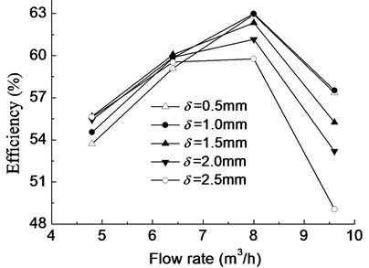
a) Efficiency curve
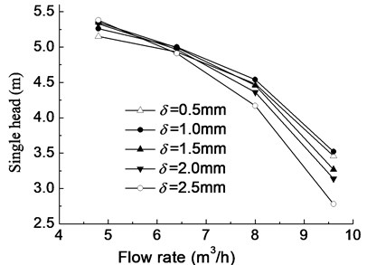
b) Head curve
According to Fig. 3, the inlet section and outlet section are at the same height, so 0, and the Eq. (1) can be simplified to the Eq. (7) as follows:
In the Eq. (7), and show the total pressure on outlet and inlet section, and theycan be obtained through the post-processing in the ANSYS Fluent, so the head can be calculated through the Eq. (7). Moreover, the sum torque on shaft can also be gained through ANSYS Fluent, the flow rate and the angular velocity of impeller are known quantities, so the efficiency can be calculated through the Eq. (2).
As can be seen from Fig. 6, the change of impeller blade thickness impacts on efficiency and head significantly, and the head curve becomes steeper with the increase of impeller blade thickness. At the design flow rate and large flow rate, the efficiency and single-stage head decrease as the increase of impeller blade thickness while instead at small flow rate, which indicates that the best efficiency point of the pump shifts to the small flow direction with the increase of impeller blade thickness. The efficiency and head change a little at design flow rate when impeller blade thickness changes from 0.5 mm to 1.5 mm. If it exceeds 1.5 mm, with the increase of thickness, the efficiency and head decrease rapidly. This means the thickness should be limited within a reasonable range.
Table 8Stress distribution for impellers with different thicknesses
Blade thickness | Inertia load | Fluid load | Combination of both loads |
0.5 mm |  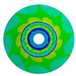 |   |   |
1.5 mm |  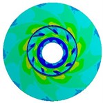 |  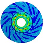 |  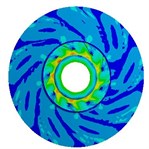 |
2.5 mm |  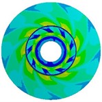 |  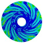 |  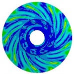 |
4.2. Effects of impeller loads on stress
Loads on stainless steel impeller consist of inertial force load caused by impeller rotation speed and fluid pressure load when pump is working. In order to compare the influence of the two loads on impeller, this study calculates respectively inertial force load, fluid pressure load, and both loads at design flow rate on stress and deformation of impeller. Table 8 means the stress distribution of impellers whose blade thicknesses are 0.5 mm, 1.5 mm, and 2.5 mm. The table indicates stress distributions on three impellers are similar. The maximum stress by fluid pressure load is much greater than those brought by inertial force load, while slightly smaller than those brought by both of them, which means that the load brought by high-pressure fluid plays a dominating role in stress distribution. Affected by three different loads, stress on impeller distributes in circumference and it is apparently larger at the inlet of blade. Besides, when the radius is the same, the stress at intersection between impeller and cover is obviously larger. With the increase of blade thickness, the maximum stress caused by inertial force load gradually increases, while the maximum stress of fluid pressure load decreases. That’s because thicker blade brings heavier impeller and larger stress caused by inertial force. Moreover, thicker blade increases the area of intersection between blade and cover, which makes impeller steady and reduces the maximum stress caused by fluid pressure. If the blade thickness is 0.5 mm, the maximum stress caused by both of the two loads is 277.29 MPa (kg/cm2) which exceeds the stainless steel’s yield strength 207 MPa; if it is 1.5 mm and 2.5 mm, the maximum stress are respectively 78.16 MPa (kg/cm2) and 50.69 MPa (kg/cm2). But the over-thick blade not only increases the cost of impeller, but also reduces the performance of pump. Hence, as a reasonable value of blade thickness of impeller, 1.5 mm is selected at last.
Table 9Deformation distribution for impellers with different thicknesses
Blade thickness | Inertia load | Fluid load | Combination of both loads |
0.5 mm |  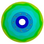 |  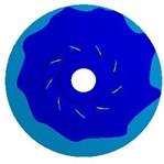 |  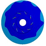 |
1.5 mm |  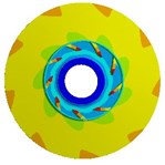 |  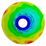 |  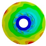 |
2.5 mm |  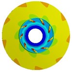 |  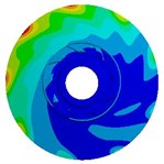 |  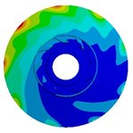 |
4.3. Effects of impeller loads on deformation
Table 9 shows the deformation distribution of impellers whose blade thicknesses are 0.5 mm, 1.5 mm, and 2.5 mm. The table indicates deformation distributions on three different impellers are similar. The maximum deformation caused by fluid pressure load is much greater than those caused by inertial force load and slightly smaller than those caused by both of them, which is similar to stress distribution illustrated above. When the thickness is 0.5 mm, the deformation caused by inertial force load increases gradually along the flow direction from inlet to outlet and at the outlet of front shroud it reaches the maximum value, while the deformation by fluid pressure load gets the highest at the blade inlet because equivalent stress here is too large and blade is too thin. Maximum deformation caused by three loads gradually decreases with the increase of blade thickness, but the position where maximum deformation appears transfers from blade inlet to outlet of front shroud. In addition, due to relatively high rigidity of cylindrical interface between the impeller and shaft, deformation in this position is always small for all load cases.
5. Conclusions
1) At design flow rate and large flow rate, the efficiency and single-stage head of stainless steel multistage centrifugal pump decrease as the increase of impeller blade thickness while instead at small flow rate, which indicates that the best efficiency point of the pump shifts to the small flow direction with the increase of impeller blade thickness.
2) Through the finite element calculation of the impeller with different blade thicknesses, distribution patterns of stress and deformation caused by inertial force load and fluid pressure load are found.
3) When the blade thickness is from 0.5 mm to 1.5 mm, the efficiency and head change a little at design flow rate; if it is more than 1.5 mm, the efficiency and head decrease rapidly with the increase of thickness. With comprehensive consideration of pump performance and strength, the blade thickness of 1.5 mm is selected at last.
References
-
Balat H. Prospec ts of biofuels for a sustainable energy future: A critical assessment. Energy Education Science and Technology Part A, Vol. 24, Issue 2, 2010, p. 85-111.
-
Demirbas T. Use of soybean as an energy source. Energy Education Science and Technology Part A, Vol. 27, Issue 2, 2011, p. 389-394.
-
Gülich J. F. Centrifugal Pumps. New York, Springer Berlin Heidelberg, 2008, p. 923-924.
-
Guan X. F. Technic Manual of Modern Pumps. Astronautics Publishing House of China, Beijing, 2011, p. 808-809.
-
Shi W. D., Wang L. G., Yu X. J. Development and prospect of deep well pump in China. Drainage and Irrigation Machinery, Vol. 27, Issue 1, 2010, p. 64-68.
-
Yao C. L., Wang C. H., Liu K., Ding L. Characters and current developments of stamping and welding centrifugal pump. Manufacturing Automation, Vol. 28, Issue 12, 2006, p. 214-215.
-
Liu Y. Y., Cai B. Y., Huo C. Y., Liu J. L., Wang G. Y. Theoretical study and engineering implementation of stamping and welding multilevel centrifugal pumps. Chinese Journal of Mechanical Engineering, Vol. 41, Issue 2, 2005, p. 228-233.
-
Liu Y., Wang G. Numerical simulation of 3d flow in low specific speed stamping multistage pump’s impellers. Journal of Agricultural Machinery, Vol. 37, Issue 11, 2006, p. 60-62.
-
Sarraf C., Nouri H., Bakir F. Experimental study of blade thickness effects on the overall and local performances of a controlled vortex designed axial-flow fan. Experimental Thermal and Fluid Science, Vol. 35, Issue 4, 2011, p. 684-694.
-
Chapple D., Kresta S. M., Wall A., Afacan A. Effect of impeller and tank geometry on power number for a pitched blade turbine. Chemical Engineering Research and Design, Vol. 80, Issue 4, 2002, p. 364-372.
-
Galletti C., Pintus S., Brunazzi E. Effect of shaft eccentricity and impeller blade thickness on the vortices features in an unbaffled vessel. Chemical Engineering Research and Design, Vol. 87, Issue 4, 2002, p. 391-400.
-
Wang C., Shi W. D., Si Q. R., Lu W. G. Influence of interstage clearance on performance of new-type well pump. Journal of Drainage and Irrigation Machinery Engineering, Vol. 32, Issue 6, 2012, p. 627-631.
-
Golcu M., Pancar Y., Sekmen Y. Energy saving in a deep well pump with splitter blade. Energy Conversion and Management, Vol. 47, Issue 5, 2006, p. 638-651.
-
Kakizaki T., Urii J., Endo M. A three-dimensional evacuation simulation using digital human models with precise kinematic joints. Journal of Computing and Information Science in Engineering, Vol. 12, Issue 3, 2012, p. 031001/1-8.
-
Wang C., Su S. Q., Shi W. D., Yao J. Numerical calculation and experimental research of pressure fluctuation in the pump under different operating conditions. Journal of Vibroengineering, Vol. 15, Issue 4, 2013, p. 2075-2082.
-
Wang Y., Wang H. Y., Xu X. M., Zhang X. Finite element computation for impeller of stamping and welding centrifugal pump. Journal of Drainage and Irrigation Machinery Engineering, Vol. 29, Issue 2, 2011, p. 109-113.
-
Wang C., Shi W. D., Li Y., Cao W. D. Structural analysis of explosion proof mine pump base on the material of QT600-3. Journal of Computational and Theoretical Nanoscience, Vol. 10, Issue 12, 2013, p. 2847-2852.
-
Yuan S. Q., Pei J., Yuan J. P. Numerical investigation on fluid structure interaction considering rotor deformation for a centrifugal pump. Chinese Journal of Mechanical Engineering, Vol. 24, Issue 4, 2011, p. 539-545.
-
Lu W. G., Zhang Q. H., Shi W. D. Impeller diameter maximum approach on deep well pump. Drainage and Irrigation Machinery, Vol. 24, Issue 5, 2006, p. 1-7.
About this article
This research was supported by the Priority Academic Program Development of Jiangsu Higher Education Institutions, the National Natural Science Foundation of China (Grant No. 51279069), the National Natural Science Foundation of Jiangsu Province (Grant No. BK20131256), the Graduate Innovation Project of Jiangsu Province (CXLX12_0642), the National Science and Technology Support Project (2011BAF14B01), Science and Technology Support Project of Jiangsu Province (BE2012150).
