Abstract
The purpose of the present study is to improve the performance of conventional high strength electrodynamic shaker. With dual armature structure, the shaker can produce strong output force. But both experimental modal analyses and finite element analyses carried out in this study indicate the structure leads to undesirable hump in its work frequency range. Hence a new shaker with single-skeleton dual coils is proposed whose shape is further optimized. The optimization adopts auxiliary boundary shape method to simulate the skeleton boundary and targets at achieving minimum weight while satisfying the first order elastic natural frequency. Then the optimized shaker is put to frequency response analyses which indicate that while maintaining the high output force of conventional shaker, the new shaker eliminates steep hump in frequency response, expands work frequency range and reduces the influence of additional mass loading of the shaker on the test object. Hence it effectively solves the flaws of the conventional high strength electrodynamic shaker.
1. Introduction
Electrodynamic shaker is an electrical-dynamic converter, that is, to convert electric energy into mechanical force to provide the exciting force to the test article [1]. Its fundamental working principle is to input current to the coil in a magnetic field so that the charged coil can receive the electromagnetism induction force. It mainly consists of a magnet structure, moving elements (including armature, which is comprised of skeleton and coil, and thrust axis), supporting spring and shell. The moving elements and support spring form the moving system of a shaker [2, 3].
According to how the magnetic field is generated, an electrodynamic shaker can be of excitation or permanent magnet type. With lower cost, smaller size and high performance, the permanent magnet shaker is widely used in production and scientific research. But being made of permeable materials and permanent magnets, its magnetic field is constant and cannot be as strong as an excitation shaker. So to increase output force, conventional high strength permanent magnet shaker adopts dual armature structure to double the output force, with each armature having independent skeleton and coil. But this structure adds to additional mass loading to the test object [4-8]. Moreover, in practice, the frequency response (FR) of dual armature shaker presents prominent hump in the work frequency range, which affects the accuracy of broadband vibration experiment and sometimes even damages the test equipment.
Previous researches attempted to expand the work frequency range of the electrodynamic shaker from the perspective of dynamic design. Researchers used finite element method and sensitivity analysis to acquire correlations between first order elastic natural frequency of the skeleton, skeleton thickness and cone angle. Correspondingly, they redesigned the skeleton structure to improve the first order elastic natural frequency, thereby broadening the frequency range [9-11]. But their models adopted 8-noded loop elements, which could only provide qualitative analysis of skelons containing lightenng holes. They failed to uncover the way rib width affects natural frequency. Nor did they define the values of design parameters for the optimum skeleton design.
To find a solution, this study adopts experimental modal analysis (EMA) and finite element analysis (FEA) to carry on a thorough study on the dual armature structure of conventional high strength electrodynamic shaker. Then it proposes a new shaker of single-skeleton dual coil structure which is further optimized.
2. Conventional dual armature structure
2.1. Current-force-magnetic field analysis
Fig. 1 shows the magnetic circuit of the dual armature structure. There are upper and lower gaps, each corresponding to one of the two armatures which are connected by a thrust axis. The two gaps share a magnet. Since their magnetic fields are opposite, to produce a uni-directional force, current of opposite direction is input to the coils.
As shown in Fig. 1, since the directions of current of two coils are opposite, the magnetizations are opposite, i.e., the magnetic fields the two coils produced have been counter-balanced and their effect on the magnet is sufficiently small. Therefore the magnetic induction intensity in gap no longer grows with the increasing current. Even when the current is very strong, its nonlinear error can still maintain at about 1 % [12]. Fig. 1 presents the current-force-magnetic field relationship of a dual armature structured shaker.
Fig. 1Current-force-magnetic field relationship of a dual armature structured shaker
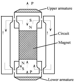
So the dual armature structure improves the non-linearality between the current and output force. Furthermore, with two armatures the shaker actually doubles its output force. With these merits, the structure leads itself to the wide application in the high strength electrodynamic shaker. But because the permanent magnet shaker is a kind of contact device and its operation principle is to transmit the electromagnetism induction force the coil produced to the thrust axis through the skeleton of armature and trough the thrust axis to the test object. As a major part of the moving system, the skeleton of armature weighs about half of the moving system. The dual armature structure increases the overall weight of the shaker and accordingly, adds to additional mass on the test object.
2.2. FR experimental measurement of dual armature structured shaker
To study the performance of conventional high strength electrodynamic shaker, this study has carried out a bare-table experiment on a V shaker of dual armature structure to measure its frequency response functions (FRF). The experiment system is shown in Fig. 2, including: Power amplifier, Hp-35670 dynamic signal analyzer, accelerometer and V shaker.
The experiment employed swept sine excitation at frequency 5-3000 Hz. For the accuracy of the observed value, it took the following issues into consideration: Firstly, a shaker is usually attached to the test object and its axial force is transmitted from its movable system to the test object through the thrust axis, so in this experiment, in order to obtain the no-load acceleration frequency, an accelerometer is adhered to the mounting table of the movable system. Special attention was given to ensure that the accelerometer was installed perpendicular to plane. Secondly, to obtain constant force output from the moving coil within a certain frequency range, the power amplifier was set at the constant flow working method.
Fig. 2Block diagram of the testing system
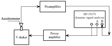
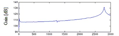
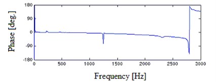
Fig. 3 presents the experimental results. Consistent with the previous theoretical analysis [1, 2], the frequency response (FR) curves show two peaks which determine the minimum value and maximum value of the shaker’s work frequency range respectively. But within the frequency range, at 1220.4 Hz there appears a prominent hump which is undesirable in broadband vibration test of high-precision.
Fig. 3FRF experimental results of V shaker of dual armature structure with the table bare
2.3. FR numerical analyses of dual armature structured shaker
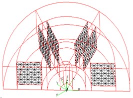
To analyze the causes of steep hump in conventional shaker’s FR within the work frequency range, a finite element model (FEM) of V shaker’s moving system was established as shown in Fig. 4. Considering the fact that among all parts of the shaker, the supporting spring plate and coil are relatively thin, this study adopted Quad 4 elements for their modeling simulation so as to improve the accuracy. Otherwise it adopted Hex 8 or Wedge 5 elements to meet the requirements of the geometry shape. Since one node of solid element has only three displacement components and no rotational components while one node of the shell element has three displacement components and two rotational components, the FEM used multiple point constraint (MPC) to connect solid elements and shell elements.
A shaker can be mounted on rigid foundations or elastically mounted to the test object. No matter how it is mounted, the shell of a shaker remains stationary at work [1]. So the six freedom degrees of the jointing supporting spring plate boundary shall be restrained.
The numerical analysis was in modality frequency response analytical method. Axial force changing with frequency ranging from 5 Hz to 3000 Hz was exerted on the armature. And eigenvalue is computed with Lanczos solution which can guarantee no root loss in solution process with Modal damp 0.006.
Fig. 4FEM of the moving system of dual armature structured shaker
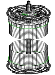
Fig. 5FRF numerical results of V shaker of dual armature structure in bare-table test
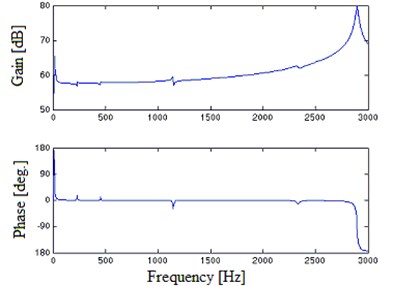
Fig. 5 shows FRF numerical results of V shaker of dual armature structure in a bare-table test. It presents a hump at 1150.5 Hz similar to the experiment with 5.73 % relative error between calculated and experimental value.
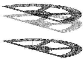
Fig. 6 is the vibration modes of the moving system of V shaker at the hump point. It shows the steep hump in the FR is caused by the axial resonance between the upper and lower armatures. This finding denies the possibility of eliminating the hump under the circumstance of dual armature structure.
Fig. 6Modes of vibration at steep hump of dual armature structured shaker’s moving system: a) at peak point, b) at trough point
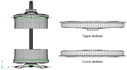
a)
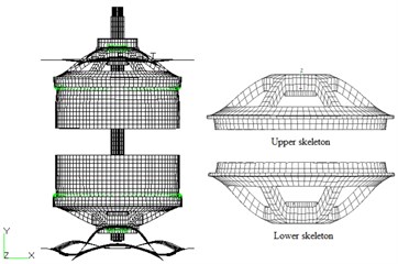
b)
3. The proposed single-skeleton dual coil structure
Aiming to ensure flat frequency characteristics, eliminate resonance effect within the work frequency range and increase the output thrust at the same time, this study proposes a single-skeleton dual coil structure, i.e. a structure of a moving system comprised of a skeleton and two coils with each installed respectively in the upper and lower gap of the magnetic circuit. The moving system is placed at the center of the shaker. Fig. 7 is the cut away view of the system. The output force is still the sum of two coils’ electromagnetism induction force. So it not only maintains the high strength of traditional dual armature structure, but also avoids axial resonance with its single skeleton and reduces the additional mass on the test object.
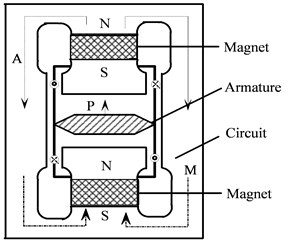
Fig. 8 shows the electric current-force-magnetic field relationship of single-skeleton dual coil structure. Similar to conventional dual armature structure, its magnetic circuit produces force in one direction. The current in two coils flows oppositely, so the magnetic field produced can be counter-balanced. Similarly non-linear relationship of the electric current and output force also will maintain sufficiently small.
Fig. 7Cut away view of moving system of single-skeleton dual coil structure: 1 – Table; 2 – Upper support spring; 3 – Thrust axis; 4 – Permanent magnet steel; 5 – Upper coil; 6 – Skeleton; 7 – Lower coil; 8 – Pole plate; 9 – Iron core; 10 – Lower support spring
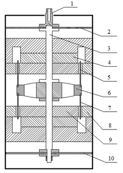
Fig. 8Current-force-magnetic field relationship of single-skeleton dual coil structure
4. Skeleton shape optimization
4.1. Problem description
First order elastic natural frequency of the skeleton of armature determines the maximum value of the shaker’s work frequency range [1]. So to broaden the work frequency range, the first order elastic natural frequency of skeleton, which is decided by its material, its supporting condition and geometric form, must be raised. This study optimizes the skeleton shape, targeting at achieving minimum weight while satisfying first order elastic natural frequency.
Fig. 9 is the FEM of skeleton in the reference design. Since the structure has planes of symmetry (), only half of the structure is taken to analysis for research convenience. According to the symmetrical boundary condition, restrain 2, 4, 6 degrees of freedom of nodes on symmetry plane.
The skeleton is made of aluminum alloy with the material parameters as: 70 GPa, 2780 kg/m3, 0.31.
Compared with the skeleton’s elasticity coefficient, the support spring plate’s axial elastic modulus is small. So the skeleton is considered free – free along axial direction in computing skeleton’s elastic natural frequency [10, 11].
In the optimization, two subcases are defined, one used in computing the structure’s first natural frequency and the other in computing the weight and element stress of structure.
Fig. 9Reference FEM of the skeleton of armature
4.2. Definition of skeleton boundary shapes
The boundary shape of skeleton is defined through auxiliary boundary shape rules, which reflect structure changes through the combination of shape change basis vectors [14]. The vectors are resulted from exerting virtual load or displacement load on the supplementary structure model which is established through adding bent plates to the prototype structure.
In the optimization, the radial dimension of the skeleton is fixed since the magnetic field size is preset. But the top and bottom shape of skeleton can change freely while the extracellular surface and two negative cambers of all lightening holes can only stretch out and draw back axially. Ribs of skeleton are free to move in their normal direction. Accordingly, two supplementary structures are taken as shown in Fig. 10.
Fig. 10Supplementary structures producing shape change basis vector: a) I, b) II
a)
b)
Fig. 11Shape change basis vectors: a) I, b) II, c) III, d) IV
a)
b)
c)
d)
As shown in Fig. 10(a), the supplementary structure produces basis vectors of top and bottom surface change. To control the change precisely, forced displacement load is exerted to the supplementary structure as shown in Fig. 11. Fig. 11(a) shows the axial quantity displacement of the top surface while Fig. 11(b) and 11(c) demonstrate first and second axial displacement of top and bottom surface respectively and simulate their geometric forms through the first and second vector curve.
The supplementary structure shown in Fig. 10(b) produces the basis vector of ribs normal direction change. It is used to control the thickness of ribs.
4.3. Establishment of optimum model
4.3.1. Objective function and design variables
The goal of dynamic skeleton shape optimization is to achieve lightest weight while satisfying the constraints of its first natural frequency and structural strength. Usually the lightest mass is taken as the objective function. But in this study it is found that using natural frequency as the objective function is better. The sensitivity coefficient ratio between design variables to construction weight is 2 magnitudes smaller than that of the first natural frequency to construction weight, so the natural frequency is taken as the objective function to achieve overall optimization.
That is:
where is the first order elastic natural frequency, is the expected value.
Design variables are the weighting coefficients of four shape basis vectors, i.e.:
The linear combination of shape change basis vectors I, II, III determines the top and bottom shape of skeleton and shape change basis vector IVdefines the sizes of lightening holes. The shape of skeleton changes with the input of different design values.
where , , , is the four shape basis vectors respectively.
4.3.2. Constraint functions
Constraint functions refer to the conditions that the optimization must satisfy. In shape optimization, they fall into are three categories: performance constraint, also called function constraint, which refers to the restrictive condition that the design should satisfy to meet the functional requirement; size constraint which stipulates the value range of design variables and boundary constraint, which ensures structure border to change according to designer’s request.
1. Performance constraints
Since the operating principle of a shaker is to transmit the electromagnetism induction force produced by armatures through skeleton to the thrust axis, which then passes the force to the test object, the skeleton plays a very important role in the transmission. Its design stress cannot exceed the material allowable stress. In this study, the skeleton is made of aluminum alloy, whose allowable stress is 240 MPa. So the design stress constraint is 240 MPa.
2. Size constraints
Size constraints refer to the upper and lower bounds of design variables, among which the maximum of three design variables corresponding to shape change basis vector I, II and III is 100 and the minimum is -100; the maximum of design variable corresponding to shape change basis vector IV is 10 and the minimum is -10.
3. Boundary constraints
In shape optimum design, it is often the case that only part of structural boundary shape needs optimization while the other important mating surfaces are required to stay unchanged. To ensure the boundary shape changes in accordance with request, motion direction of the boundary surface nodes must be given in the optimal process.
4.4. Optimization results and analysis
On the platform of MSC/Nastran, using several techniques including coupling design variable linking, constraint screening and sensitivity analysis, this study first has built an approximate model and obtained the optimization model through sequence quadratic programming method [14-23]. As shown in the course chart in Fig. 12, after 8 optimizing design cycles, objective function converges to the optimal solution, in which skeleton value of first order natural frequency reaches the desired target value of 5000 Hz under the constraint conditions. The skeleton weighs 520.8 g, 38.77 % less than the initial 850.6 g. Table 1 demonstrates the optimization results.
Fig. 12Optimization course chart of objective function
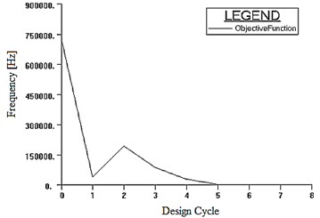
Table 1Initial value and optimal solution of design variables
Design variable | Initial value | Optimal solution |
-20.0 | -31.667 | |
4.0 | 1.1755 | |
4.0 | 1.1566 | |
1.0 | 1.7129 |
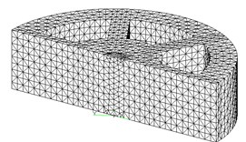
Fig. 13 is the FEM of the optimized structure (half the structure). As the figure shows, the structure edge compresses axially and the ribs width increases, which indicates rib width affects the structure’s first order natural frequency and its increase can reduce the thickness of skeleton, thus leading to the considerable decrease of overall structure weight.
Fig. 13FEM of the optimized structure: a) axonometric view, b) front view
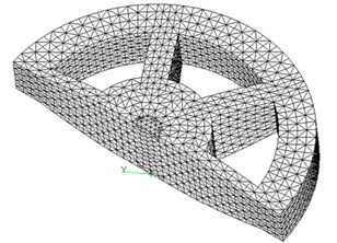
a)
b)
5. FR numerical analyses of single-skeleton dual coil structured shaker in bare-table test
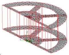
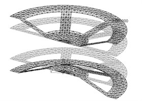
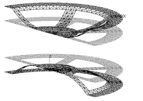
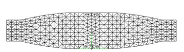
Fig. 14 is the FEM of the moving system of optimized single-skeleton dual coil structured shaker. Modality frequency response analysis has been carried out at frequencies ranging from 5 Hz to 6000 Hz and a modal damping ratio of 0.006.
Fig. 14FEM of the moving system of optimized single-skeleton dual coil structured shaker
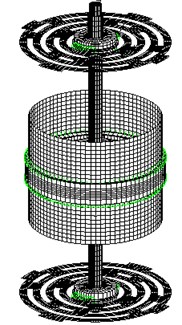
Fig. 15FRF of single-skeleton dual coil shaker with the table bare
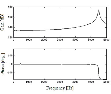
Fig. 15 is the FRF of optimized single-skeleton dual coil shaker under bare table conditions. The FR curve shows desirable frequency and phase characteristics. The first order elastic natural frequency of skeleton reaches 5486.2 Hz. It means the maximum value of the shaker’s work frequency range has attained the design objective. Meanwhile there exists no prominent hump within the freqency range. So the optimized single-skeleton dual coil structured shaker not only expands its work frequency range, but also avoids the resonance effect in the work frequency range and eliminates steep hump. At the same time, it maintains the merit of traditional dual armature structure of strong force output.
6. Conclusions
1. With the combination of EMA and FEA, this study has found out the causes of steep hump appearing in the FR of conventional high strength electrodynamic shaker within its work frequency range. Dual armature structure can enhance the output force and improve the non-linear relationship of electric current and output force. But its symmetry of axial structure leads to the inevitable steep hump in the FR within the work frequency range.
2. As an effort to improve the performance of high strength electrodynamic shaker, this study proposes a new shaker of single-skeleton dual coil structure. The research findings indicate while maintaining the merit of traditional shaker, the new shaker not only avoids the resonance effect of the shaker within the work frequency range, but also reduces the additional mass load on the test object.
3. In order to expand the work frequency range, this study carries on structural optimization of the skeleton in the proposed shaker. The optimized shaker is put to frequency response analysis. The result shows its work frequency range is up to the anticipation. At the same time the shaker achieves a minimum weight.
References
-
Zhao C. S. A research on electrodynamic shaker. Nanjing University of Aeronautics and Astronautics, 1990, (in Chinese).
-
Lang G. F. Electrodynamic shaker fundamentals. Sound and Vibration, Vol. 31, Issue 4, 1997, p. 14-23.
-
Zhang S. Vibration Test and Analysis Technology. Tsinghua University Press, Bei Jing, 1992, (in Chinese).
-
Lang G. F. Understanding the physics of electrodynamic shaker performance. Sound and Vibration, Vol. 35, Issue 10, 2001, p. 24-33.
-
Zhao C. S., Bao M. The research and the engineering application of electrodynamic vibrators. Journal of Nanjing University of Aeronautics & Astronautics, Vol. 25, Issue 5, 1993, p. 638-645, (in Chinese).
-
Zhao C. S. Research on high energy shaker and its applications in engineering. Measurement & Control Technology, Vol. 15, Issue 3, 1996, p. 8-11, (in Chinese).
-
Bi S. S., Ren J., Wang W., Zong G. H. Elimination of transducer mass loading effects in shaker modal testing. Mechanical Systems and Signal Processing, Vol. 38, Issue 2, 2013, p. 265-275.
-
Schlegel C., Kiekenap G., Glöckner B., Kumme R. Sinusoidal calibration of force transducers using electrodynamic shaker systems. Sensors and Transducers, Vol. 14, Issue 1, 2012, p. 95-111.
-
Zhao C. S., Liu Q. Sensitivity analysis for the armature of an electrodynamic vibrator. 1st U.S. National Congress on Computational Mechamics, Chicago, USA, 1991.
-
Li H., Yang B., Yan G., Hu J. Vibration control simulation of an electrodynamic shaker based on an electromagnetic finite element model. International Journal of Applied Electromagnetics and Mechanics, Vol. 39, Issue 4, 2012, p. 769-777.
-
Liu X., Chen Z. b., Xu L. F., Huang S. Y. The study and application of electromagnetic vibration shaker finite element model updating and validation technology. Key Engineering Materials, Vol. 458, Issue 11, 2011, p. 231-236.
-
Fei Z. Y. Dual coil structure and semi-directional technology: a design method improves non-linearality of electrodynamic shaker. Vibration and Dynamic Test, Vol. 4, 1984, p. 9-11, (in Chinese).
-
Chen T. Y., Huang J. H. An efficient and practical approach to obtain a better optimum solution for structural optimization. Engineering Optimization, Vol. 45, Issue 8, 2013, p. 1005-1026.
-
Zhou L. Z., Liu D. F. Shape optimization of electrodynamic shaker skeleton. Mechanical Design, Vol. 11, Issue 1, 2006, p. 61-63, (in Chinese).
-
Liu Y., Shimoda M. Parameter-free optimum design method of stiffeners on thin-walled structures. Structural and Multidisciplinary Optimization, 2013, p. 1-9.
-
Baldomir A., Hernandez S., Diaz J., Fontan A. Sensitivity analysis of optimum solutions by updating active constraints: Application in aircraft structural design. Structural and Multidisciplinary Optimization, Vol. 44, Issue 6, 2011, p. 797-814.
-
Bi S. H., Ren J., Wang W., Zong G. H. Elimination of transducer mass loading effects in shaker modal testing. Mechanical Systems and Signal Processing, Vol. 38, Issue 2, 2013, p. 265-275.
-
Grice R. M., Pinnington R. J. An electrodynamic shaker with an integral force gauge for high-frequency measurements on lightweight structures. Proceedings of the Institution of Mechanical Engineers, Part C: Journal of Mechanical Engineering Science, Vol. 214, Issue 10, 2000, p. 1285-1297.
-
Li H., Yang B. K., Yan G. R., Hu J. W. Vibration control simulation of an electrodynamic shaker based on an electromagnetic finite element model. International Journal of Applied Electromagnetics and Mechanics, Vol. 39, Issue 1-4, 2012, p. 769-777.
-
Zhou L. Z., Liu D. F. Product shape optimization based on MSC/NASTRAN. Machinery Design & Manufacture, Issue 10, 2006, p. 15-17, (in Chinese).
-
Balaji R., Piotr B., Yves T., Pierre V. Towards a space reduction approach for efficient structural shape optimization. Structural and Multidisciplinary, Vol. 48, Issue 5, 2013, p. 987-1000.
-
Azegami H., Shota F., Taiki A. Shape optimization of continua using NURBS as basis functions. Structural and Multidisciplinary Optimization, Vol. 47, Issue 2, 2013, p. 247-258.
-
Dagys D., Ostasevicius V., Gaidys R. Parametrization-based shape optimization of shell structures in the case of free vibrations. Journal of Vibroengineering, Vol. 10, Issue 2, 2012, p. 196-202.
About this article

This paper is supported by Specialized Research Fund for the Doctoral Program of Higher Education of China (Grant No. 20113218110002) and a Project Funded by the Priority Academic Program Development of Jiangsu Higher Education Institutions of China.
