Abstract
As the research object is to set up four-stroke direct injection diesel engine pistons, with the research method of thermo-mechanical coupling, a three-dimensional finite element analysis model is established. Calculate transient heat transfer coefficient and the transient gas temperature. Piston stress is calculated under the conditions of thermal load, mechanical load and the thermal-mechanical coupling load. Results show that, the piston safety, the main cause of the piston deformation and the great stress is the temperature so it is feasible to further decrease the piston temperature with structure optimization.
1. Introduction
As the main heated part of the engine, the piston has to bear the complicated mechanical load and thermal load subjected to periodical change. An analysis to the stress and the deformation condition under the mechanical load or the thermal load only is far from enough to reflect the actual working condition of the piston. A reference can only be provided for the piston design with factors influencing the thermal load found out, taking into overall consideration the piston intensity under the coupling effect of the thermal load and mechanical load.
Nowadays, thermo-mechanical coupling analysis work includes: Bao-Lin Wang, Yiu-Wing Mai [1] establishes a solution method for the one-dimensional (1D) transient temperature and thermal stress fields in non-homogeneous materials. Douglas M. Baker, Dennis N. Assanis [2] presents a methodology for a coupled thermodynamic and heat transfer analysis of diesel engine combustion chambers. P. O’Hara [3] analyzes heat transfer problems exhibiting sharp thermal gradients using the classical and generalized finite element methods. U. A. Benz, J. J. Rencis [4] a dual reciprocity boundary element formulation using quadratic elements is presented for coupling two-dimensional and axisymmetric zones for transient heat transfer applications. Sook-Ying Ho, Allan Paull [5] describes a relatively simple and quick method for implementing aerodynamic heating models into a finite element code for non-linear transient thermal-structural and thermal-structural-vibrational analyses of a Mach 10 generic HyShot scramjet engine. Elisa Carvajal Trujillo [6] proposes a methodology for the estimation of the mean temperature of the cylinder inner surface in an air-cooled internal combustion engine.
Based on the fundamental of thermal analysis, this paper analyzes the stress of the piston under the conditions of thermal load, mechanical load and coupled load. It compares with the stress and deformation condition under the coupling effect of the thermal load and mechanical load respectively. Through the analysis, it is concluded that the main factor influencing the piston intensity is the temperature, thus providing basis for the optimization design of the piston.
2. Finite element model
2.1. Geometrical model
To establish reasonable and accurate finite element model is the most important part of the piston finite element analysis. Then, it carries out analysis by marking element grids to obtain the accurate results finally. According to the structural symmetry of the piston, in order to be convenient for calculation and decreasing workload, cut the established piston model to maintain 1/4 and then import the model to the finite element software for the finite element analysis to the piston according to the fine interface between the modelling software and the finite element analysis software. During the importing process, some details have been omitted, such as the chamfer and the snap ring of the piston pin etc. The geometrical model for the piston is as shown in Fig. 1. Physical properties of the piston material is as shown in Table 1.
Table 1Parameters of the piston material
Parameters | Values of the parameters |
Piston material | ZL109 |
Poisson ratio | 0.32 |
Elastic modulus of the piston | 70 GPa |
Material density | 2700 kg/m3 |
Conductivity factor | 160 w/(m2·K) |
Coefficient of thermal expansion | 21×10-6 m/K |
Fig. 1Geometrical model of the piston
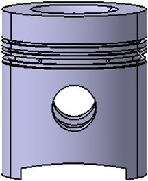
Fig. 2Finite element model of the piston

2.2. Mesh generation
Considering the two different situations of mechanical analysis and thermal analysis, mesh for piston entity model choice of two elements of the mesh is not consistent. Choose element type SOLID45 in mechanical analysis, and choose element type SOLID70 in the thermal analysis. Overall, the smaller the element division is, the more accurate the calculation, but it needs more time. During the mesh generation for the piston model, it needs experiences and several trials. The finite element model of piston is as shown in Fig. 2.
3. Thermal load analysis to the piston
3.1. Basic theory for thermal analysis
To solve the temperature field of an object is the precondition necessary for the calculation of thermal stress. Then it obtains the thermal strain, and then carries out the accumulation with the positive strain and shears strain of the mechanical load.
Based on the basic theory for heat transmission, we can deduce the differential equation of the heat transmission for the object with the internal heat source and the transient temperature field:
where, is the transient temperature value of the object, is the time, is the conductivity factor of the material, is the material density, is the specific heat capacity of the material and is the internal heat source intensity of the material. Usually, , , and are treated as constants, while the stable thermal analysis has nothing to do with the time variable , and no internal heat source has to be taken into consideration for the finite element analysis to the piston. So we can get:
Besides, to get the unique solution for the aforesaid differential equation, the initial condition and the boundary condition should be added, which are collectively called the definite condition. Then we get coupling solution for the differential equation. In this paper, the third boundary condition is applied for solving and analyzing the temperature field for the piston, which means that the temperature and the heat exchange coefficient of the fluid medium contacting the object is treated as the variables whose constants have been known. We can express in the equation as follows:
where, is the exterior normal vector for the object boundary, is the convection heat exchange coefficient and is the temperature of the surrounding medium.
The finite element analysis for the temperature field of the piston is to get the extreme value the functional of the differential equation with the variation principle, based on the functional principle of the differential equation, thus solving the equation set with the node temperature as the unknown variable. Based on the variation principle, the functional equation for solving the node temperature is:
where, is the piston boundary and is the solution zone for the piston body.
The temperature function of the piston temperature field meeting the boundary condition is obtained by carrying out variation to the aforesaid functional and obtaining the minimum solution as follows:
After discreting the piston body with the finite element method, every element can be considered as the sub-domain of the integral computational domain, thus obtaining , where is the sub-domain for every cell.
While the functional equation for the cells within the sub-domain can be expressed as:
The temperature value of any point within the cell applies the node temperature of the cell to carry out interpolation function and obtain with calculation:
where, and are the shape function and the temperature cell node respectively and is the number of cell nodes.
3.2. The thermal boundary conditions
The piston temperature field belongs to the three dimensional unsteady field, and its computation is very complex. When the diesel engine running in a steady condition, the piston top gas temperature changed a lot in one work cycle, but the time of change is very short, temperature fluctuations within the scope of the piston top surface under the action of thermal inertia, in the vast area of the piston structure, the temperature of the piston is basically steady, which can be thought of as the piston temperature field which does not change with time.
Fig. 3AVL-BOOST model of the piston
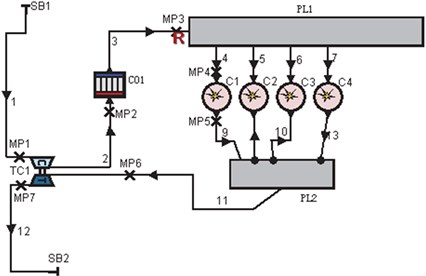
Fig. 4The transient gas temperature
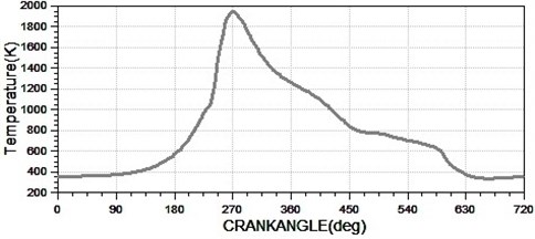
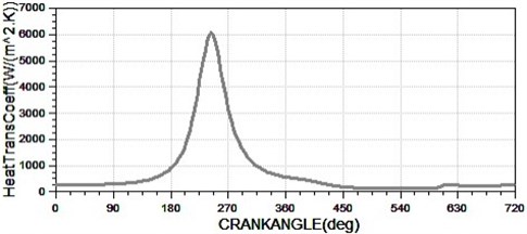
Fig. 5The transient heat transfer coefficient
For the calculation of average heat transfer coefficient in internal combustion engine heat load, it generally has crank angle express, a work cycle is 720°, so:
Take some crank angle as the interval, the value interval can be appropriately reduced in the compression stroke and power stroke due to gas pressure’s quick changes. The AVL-BOOST calculates the corresponding and .
According to the above calculation, , the temperature of the gas integrated average temperature is based on gas, its calculation formula:
Calculate the Eq. (9), . The piston thermal boundary conditions are listed after repeating adjustment calculated as shown in Table 2.
Table 2Heat exchange coefficient and temperature of the piston
Location | Ambient temperature | Heat exchange coefficient |
Piston crown | 741 | 460 |
Combustion chamber | 741 | 400 |
Fire bank | 180 | 88 |
Top edge of the first circular groove | 180 | 384 |
Inner edge of the first circular groove | 180 | 246 |
Bottom edge of the first circular groove | 180 | 2162 |
Top edge of the second circular groove | 160 | 390 |
Inner edge of the second circular groove | 160 | 182 |
Bottom edge of the second circular groove | 160 | 390 |
Bottom ring land of the first ring | 180 | 88 |
Bottom ring land of the second ring | 160 | 88 |
Top edge of the third circular groove | 140 | 277 |
Inner edge of the third circular groove | 140 | 40 |
Bottom edge of the third circular groove | 140 | 277 |
The piston skirt | 120 | 341 |
Top of the intracavity | 100 | 2000 |
Middle of the intracavity | 95 | 1800 |
Lower of the intracavity | 90 | 1500 |
3.3. Thermal stress analysis to the piston
In the thermal stress analysis, it is necessary to convert thermal element within ANSYS to structural element and thermal element of solid 70 to structural units of solid45. After conversion, the thermal stress analysis can be carried out.
It is necessary to make sure that no rigid body displacement will occur to the model. So it is necessary to carry out constraint to the piston in every direction, and the constraint applied cannot bring in additional mechanical load. The applied temperature load during the thermal stress analysis is the temperature load when the result of the temperature field automatically converts to nodes.
Because the mode is 1/4 model, it is necessary to apply the symmetry constraint to the piston. Select the plane sectional view of the piston, set its -direction displacement as 0; select on a plane cross-sectional view; set the displacement of the direction is 0; select the piston pin hole plane, set the radial displacement (i.e., direction) 0. The temperature field is generated when the th file completes temperature load superimposed, thus obtaining the thermal stress distribution nephogram of the model, as shown in Fig. 6.
The stress distribution nephogram of the piston is as shown in Fig. 6. Seen from the figure, the maximum stress for the piston is 250 MPa and the part with rapid change of the stress occurs in the pin boss. The reason for this phenomenon is that the pin boss chamfer is omitted in the import procedure of the model, thus causing the stress concentration. Besides, in actual condition, the existence of the rounded corner will further decrease the stress value, thus mitigating the stress, so that the overall stress distribution of the piston is reasonable.
Fig. 6Thermal stress nephogram
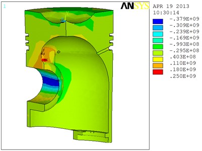
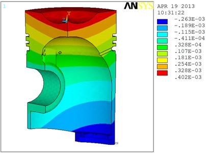
Fig. 7Thermal deformation of the piston
3.4. Thermal deformation analysis to the piston
Thermal deformation of the piston occurring in the temperature load is as shown in Fig. 7.
Seen from Fig. 7, the maximum deformation occurs at the edge of the piston top is free from constraint, with the value of 0.402 mm. Seen from the figure, the deformation from the piston top surface to the skirt and from the interior of the piston to the exterior is decreased gradually. This is in consistency to the temperature field of the piston, indicating that different expansion deformation will occur to the same material in different temperatures.
4. Thermo-mechanical coupling analysis to the piston
4.1. Mechanical load analysis to the piston
Select the maximum explosion pressure conditions as the calculation condition. Regard the load of the gas pressure inside the cylinder as pressure, make the top of piston to receive the high pressure.
From Fig. 8, the stress concentration parts of the piston are distributed within the piston pin boss and the point where the pin boss contacts the inner cylinder, with the maximum stress in the forward direction is 18.9 MPa. The stress concentration occurs because displacement constraint is applied to this part, thus the stress is changed sharply and in the meantime, no rounded corner treatment is carried out during the import procedure of the model; in the actual condition, the stress within the piston structure will be smaller, thus the piston is safe.
4.2. Coupling analysis to the piston
Piston bear the coupling effect of the high-temperature gas and mechanical pressure, in the same plane of symmetry constraints, and is constrained at the bottom of link. Piston brings about the coupled stress. Although the thermal load and mechanical load are two kinds of different loads acting on the piston, they will both affect the reliability and endurance of the operation of the piston. Deformation occurs to the piston under the effect of the thermal load and the piston deformation will affect the transfer of heat, the thermal stress and the mechanical stress. Therefore, it is necessary to integrate the dual function of the thermal stress and the mechanical stress of the piston to carry out coupling analysis and solve so as to better reflect the stress field distribution and deformation condition of the piston in the operation condition.
Fig. 8Mechanical stress nephogram
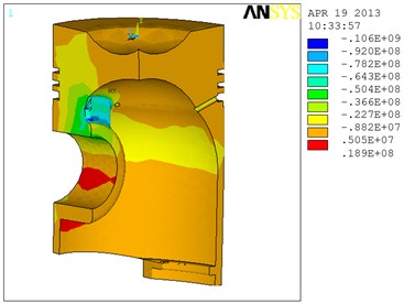
Fig. 9Thermo-mechanical coupling stress nephogram
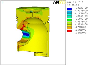
From Fig. 9, we can get the thermo-mechanical coupling condition of the piston and that the stress concentration occurs at the piston pin boss and the ribbed plate, with the maximum value in the forward direction of 144 MPa, which is 250 MPa smaller than the allowable stress of the piston, so the piston is safe. But with the combined effect of the thermal load and mechanical load, the thermal load plays the main role.
5. Transient dynamics analysis
The transient dynamics analysis is a method of dynamics response to determine the load which changes with the time. It can analyze the displacement, strain and stress changes with the time under the state of static load, transient load and harmonic load and the combination function. Load and time correlation makes the force of inertia and damping effect obviously.
The loads applied to the piston in the cycle before are divided into several steps of loads, apply the corresponding loads of each moment to the piston. The whole process is divided into 84 steps of load application and the applied time and the corresponding loads.
We define that the analysis type of the piston is the transient kinetic analysis and select the complete method to carry out analysis. The transient kinetic analysis of the piston is divided into 84 load steps. Fig. 10 is stress nephogram of the piston, when we can see the entire and partial stress of the piston directly. Express the deformed image of the piston when completing a cycle, select several typical load step analysis and take the stress nephogram of the piston in the direction of the -axial as an example to illustrate the stress condition of the piston. Fig. 10 is the stress nephogram of the 30th load step. From Fig. 10, we can see that the stress concentration phenomenon occurs at the reinforcing rib, which we should pay attention to when designing so as to reduce stress concentration.
Fig. 10Stress nephogram of the 30th load step of the piston
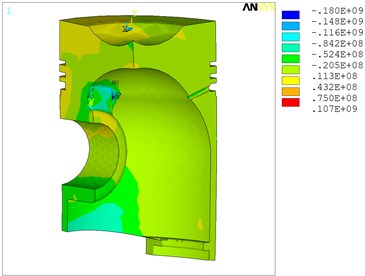
Fig. 11The stress-time response curve of node 309
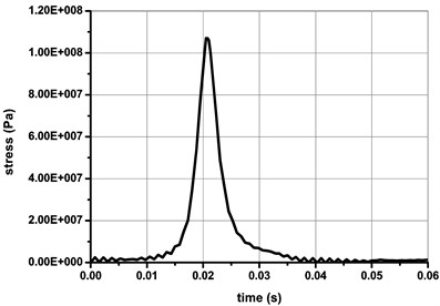
The stress-time response curve for the node number 309 (this node does experience the highest stress) is shown in Fig. 11. It can be seen that the maximum stress at this node is 107 MPa. In overall consideration of the stress-time response curves as stated above, it is easy to figure out from the figures that the corresponding moment of the maximum stress calculated is approximately at 0.02075 second; because the dangerous moments are almost the same in several figures, the maximum stress is not only the dangerous moment of a certain node of the piston for the use of a certain unit, but also the entire dangerous moment for the piston.
6. Conclusions
By thermo-mechanical coupling analysis, we can get the stress distribution and the deformation condition for each part of the piston. The maximum thermal stress of the piston is 250 MPa and the maximum mechanical stress is 18.9 MPa. The maximum deformation under the effect of the thermal stress is 0.402 mm. With the thermo-mechanical coupling analysis, we can get that the maximum of the stress to the piston is 144 MPa, and the stress value is within the allowable range, so the piston is safe. The maximum stress value appears in the vicinity of the pin boss, so in this region it must have the right Chamfer, to prevent stress concentration. Thermal stress dominates in this piston, temperature is the main reason for thermal stress that generated in the piston, so try to reduce the temperature, the stress below the tensile strength of the piston, so the piston safety.
References
-
Bao-Lin Wang, Yiu-Wing Mai Transient one-dimensional heat conduction problems solved by finite element. International Journal of Mechanical Sciences, Vol. 47, 2005, p. 303-317.
-
Douglas M. Baker, Dennis N. Assanis A methodology for coupled thermodynamic and heat transfer analysis of a diesel engine. Applied Mathematical Modelling, Vol. 18, 1994, p. 590-601.
-
O’Haraa P., Duartea C. A., EasonbT. Generalized finite element analysis of three-dimensional heat transfer problems exhibiting sharp thermal gradients. Computer Methods in Applied Mechanics and Engineering, Vol. 198, 2009, p. 1857-1871.
-
Benz U. A., RencisJ. J. Coupling two-dimensional and axisymmetric boundary element zones for transient heat transfer applications. Engineering Analysis with Boundary Elements, Vol. 26, 2002, p. 455-467.
-
Sook-Ying Ho, Allan Paull Coupled thermal, structural and vibrational analysis of a hypersonic engine for flight test. Aerospace Science and Technology, Vol. 10, 2006, p. 420-426.
-
Elisa Carvajal Trujillo, Francisco J. Jiménez-Espadafor, José A. Becerra Villanueva, Miguel Torres Garcí A methodology for the estimation of cylinder inner surface temperature in an air-cooled engine. Applied Thermal Engineering, Vol. 31, 2011, p. 1474-1481.
-
Hidehiko Kajiwara, Yukihiro Fujioka, Tatsuya Suzuki, Hideo Negishi An analytical approach for prediction of piston temperature distribution in diesel engines. JSAE Review, Vol. 23, 2002, p. 429-434.
-
Avinash Kumar Agarwal Time resolved numerical modeling of oil jet cooling of a medium duty diesel engine piston. International Communications in Heat and Mass Transfer, Vol. 38, 2011, p. 1080-1085.
-
OngJ. H. Steady state thermal analysis of a diesel engine piston. Computers and Industrial Engineering, Vol. 15, 1990, p. 255-258.
-
Wu H. W., ChiuC. P. Finite element model for thermal system in real time operation diesel piston. Computers and Structures, Vol. 32, 1989, p. 997-1004.
-
Rakopoulos C. D., MavropoulosG. C. Components heat transfer studies in a low heat rejection diesel engine using a hybrid thermostructural finite element model. Applied Thermal Engineering, Vol. 18, 1988, p. 301-316.
-
Keribar R., MorelT. Methods for thermomechanical analysis of thermal barrier coatings in diesel engines. Surface and Coatings Technology, Vol. 30, 1987, p. 63-71.
-
Wang Yanxia, Dong Yuzhen, Liu Yongqi Simulation investigation on the thermo-mechanical coupling of the QT 300 piston. Second International Conference on Information and Computing Science, Vol. 4, 2009, p. 77-80.
-
Yuanhong Li, Song-Charng Kong Coupling conjugate heat transfer with in-cylinder combustion modeling for engine simulation. International Journal of Heat and Mass Transfer, Vol. 54, 2011, p. 2467-2478.
-
Wu Yong-Hai Temperature field simulation and analysis of cylinder-jacket component of diesel engine based on fluid-solid-heat coupling. Second International Conference on Information and Computing Science, Vol. 4, 2009, p. 156-159.
-
Jarruwat Chareonsuk, Passakorn Vessakosol Numerical solutions for functionally graded solids under thermal and mechanical loads using a high-order control volume finite element method. Applied Thermal Engineering, Vol. 31, 2011, p. 213-227.
-
Abbes M. T., Maspeyrot P., Bounif A., Frene J. A thermomechanical model of a direct injection diesel engine piston. Proceedings of the Institution of Mechanical Engineers Part D-Journal of Automobile Engineering, Vol. 218, 2004, p. 395-409.
-
Evangelos G. Giakoumis Lubricating oil effects on the transient performance of a turbocharged diesel engine. Energy, Vol. 35, 2010, p. 864-873.
-
Joseph Padovan, Mike Adams, Demeter Fertis, Ibrahim Zeid, Paul Lam Nonlinear transient finite element analysis of rotor-bearing-stator systems. Computers and Structures, Vol. 18, 1984, p. 629-639.
-
Boedo S., BookerJ. F. Transient dynamics of engine bearing systems. Tribology Series, Vol. 14, 1989, p. 323-332.
-
SoizeC. Transient responses of dynamical systems with random uncertainties. Probabilistic Engineering Mechanics, Vol. 16, 2001, p. 363-372.
-
Roques S., Legrand M., Cartraud P., Stoisser C., Pierre C. Modeling of a rotor speed transient response with radial rubbing. Journal of Sound and Vibration, Vol. 329, 2009, p. 527-46.
About this article

