Abstract
Dynamic tension variation caused by conductor galloping is a major impact on design and stable operation of overhead transmission lines. A formula to calculate tension variation caused by the conductor galloping was presented in this paper by using the energy balance method. And two important parameters and were proposed by the dimensionless analysis to study the factors influencing the dynamic tension. By comparison with the popular expression obtained by the length variation method, the formula deduced in this paper has more extensive applications and it was simplified to obtain the expression derived by the length variation method as the parameters and have the smaller values. Using the actual galloping conditions, the tension variation maximum against the different parameters was obtained and it can go up to 3-4 times as large as the initial tension for some extreme cases. Additional a finite element galloping model was used to verify the theoretical expression. The results by the theoretical calculation were agreement well with the numerical simulated values except the extremely large amplitude galloping conditions.
1. Introduction
Dynamic tension is one of the most important controlling loads for the design of transmission lines besides static tension [1-3]. Dynamic tensions can mainly be caused by large amplitude conductor oscillations, including ice shedding [4-5], galloping [6] and wind-induced swing [7-8], etc. In these cases, conductor galloping is the most dangerous phenomenon and has a major impact on the design of transmission lines. Conductor galloping can cause such severe disruptions as short circuit, flashover between phases and great damage to conductors, fittings or tower components [1].
Galloping is characterized by conductor motions which amplitudes may approach or exceed the conductor sag. Large amplitude oscillations can lead to excessive tension variations around the initial value [9]. And tension variations depend on galloping amplitudes and number of loops. Generally, galloping is a low frequency, high amplitude wind induced vibration of a single or a few loops of standing waves per span, which can make terrible tension changes on conductors. It is the most significant reason that larger load variations occur between each side of a given tower, between sub-conductors for bundle conductors, and between phases during conductor galloping which is sometimes destructive to lines system. So tension variation characteristics on galloping are a major consideration on designing and operating of overhead transmission lines, especially for both clearances and tower components [10].
Existing dynamic tension calculation on galloping conductors is based on the length variation as a result of lines galloping, which has been widely studied in the literatures [11-13]. Zhu et al. [11] have evaluated the theoretical formula by testing results. Wang et al. [12] have studied to decompose the theoretical formula into horizontal and vertical tensions at the suspension point. But the formula deduced by length variation method is approximate by neglecting high order elements. Wang [13] showed the tension difference between adjacent spans by modeling the insulators separately using finite element method. Nonetheless the simulation of suspension insulators is more complex and it need be remodeled for every line and insulator structure. [1] showed a detailed analysis and summary for the dynamic load on towers by the tension variations on conductor galloping. The conclusions in this literature showed that the tension variation is from 0 to 2.2 times as large as the static value in the condition of anchoring level and the vertical load is from 0 to 2 times as large as the static value for suspension level.
In this paper, a dynamic tension calculation method is presented with the energy principle. And the approximation formula is also generalized to calculate the tension variation on galloping conductors. In contrast with the expressions deduced by length change method, the formula in this paper is more universal and the detailed discussion is also presented to the different results obtained by two different methods. In addition, because the influencing parameters to calculate dynamic tension are complicated, dimensionless parameters are deduced to describe multiple parameters influence. Finally, a practical example is presented to illustrate the applicability of the calculation method.
2. Formulation
Generally, there are three different wind-induced vibration phenomena on conductors, namely aeolian vibration, galloping and subspan oscillation. Aeolian vibration is a typical vortex-induced vibration with low amplitude and high frequency. Galloping is a self-excited vibration by the wind force with high amplitude and low frequency, and this vibration occurs commonly on iced conductors. Subspan oscillation is a wake-induced vibration peculiarly to bundled conductors with amplitude and frequency in between aeolian vibration and galloping. In this study, we only focus on the conductor galloping phenomenon which has a major impact on the design of overhead lines as large load variations may occur between phases and even between each side of a given tower.
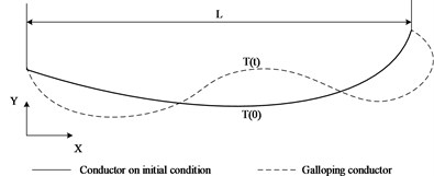
In essence, as a typical self-excited vibration phenomenon, conductor galloping takes the basic form of standing waves and/or traveling waves with small numbers of loops [1]. Fig. 1 gives the schematic of a typical conductor galloping type with the third mode shape. In fact, it is very difficult to calculate dynamic response and dynamic stress variation accurately on galloping conductors because of complex nonlinearities with large deformation and aerodynamic load. And research effort is continued in this field [14-17].
Fig. 1The schematic of a typical conductor galloping type with the third mode shape
But in the point of energy, galloping excitation is a process that the conductor absorbs wind energy continuously and finally obtains a relatively stable oscillation mode based on energy balance. According to the structural dynamics theory, wind energy absorbed by the conductors can convert into kinetic energy, potential energy, deformation energy and dissipation energy by damping of the line system. In practice, the energy dissipated by the damping of conductors and fittings can be neglected because the damping coefficients are very small based on the testing results. If take no account of extreme cases, conductor plastic deformation and the dynamic behaviour of the tower components on galloping can also be neglected to calculate energy dissipation. So when conductor galloping is in the stable condition, the energy balance equation can be expressed as follows:
where is the kinetic energy:
is the potential energy:
is the deformation energy. Because of the above hypothesis, the conductor plastic deformation and the tower components deformation are neglected. And for the sake of simplicity in this demonstration, energy obtained by conductor torsional deformation during galloping can also be regarded as a small term, especially for single conductors. So can be only expressed as elastic deformation energy:
And from above expressions, is the conductor galloping displacement in the vertical relative to the initial position, is the linear velocity as conductor galloping, is the variable tension with time dependence, is the span length, is the iced conductor mass per unit length, is gravitational acceleration, is conductor equivalent modulus of elasticity, is the area of conductor section.
Based on the wide observations for galloping accidents and relevant research achievements, the conductor galloping mode is generally a single or a few loops of standing waves per span. So the oscillation trajectory can be expressed approximately as a trigonometric function:
where is the conductor galloping amplitude, is the galloping mode number, is the galloping frequency.
Supposing that when 0, and based on the Eq. (5) the velocity can be expressed as follow:
where, and are the conductor galloping amplitudes in the vertical direction and the horizontal direction, respectively.
Substituting Eqs. (2)-(6) into Eq. (1), the expression of variable tension with time dependence can be obtained:
And if this inequation:
is satisfied, the right side term of Eq. (7) can be expended by power series as follow:
Let that:
and suppose that:
Substituting Eqs. (10a)-(10b) into Eq. (9) and omitting higher order terms, the approximate expression for variable tension can be obtained:
Substituting Eqs. (10a)-(10b) into Eq. (8), the conditions that Eq. (11) holds can be deduced as follow.
1) When is even number, the following expression can be obtained:
2) When is odd number, the following expression can be obtained:
where is the conductor maximum sag in the initial location.
It is obvious that the expression in Eq. (11) is the same with the formula deduced by the length variation method [2-3]. And only when Eqs. (10) and (12) are all satisfied, Eq. (11) can be deduced from Eq. (7). If Eq. (12) is unsustainable, the results obtained from Eq. (11) are divergent.
In order to analyze influencing factors to tension variation, a dimensionless expression deduced from Eq. (7) can be obtained:
The maximum of tension variations is also an important parameter on design and analysis. From Eq. (13), the expression of tension maximum can be obtained as follows.
1) When is even number, reaches the maximum when :
2) When is odd number, reaches the maximum when :
From Eq. (13), choose the dimensionless parameters , . Then Eq. (14) can be transformed into:
where .
From Eq. (15), the tension variation maximum lies only on and when is a even number, and it is only the function of , and when is an odd number. The parameter can be regarded as relative tension, expresses relative galloping amplitude and expresses relative initial sag.
3. Analysis results
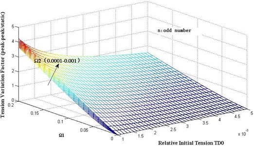
In analysis results, we need to consider reasonable value for parameters and based on engineering actuality. From the expressions of and , galloping amplitude is the most important parameter, but hitherto there is no accurate expression except some testing statistical results [18]. So based on existing empirical formulae, the variation range for parameter is [0, 0.2] and is in the range [0.0001, 0.001] when is an odd number.
Firstly, assume that the number of galloping loops is even. In order to describe the tension variation ratio, define the tension variation factor as follows:
Fig. 2 gives the ratio of tension variation to the initial tension with different parameter and relative initial tension . The results show that the tension variation on galloping can go up to 3-4 times as large as the initial tension for the extreme cases. Tension variation factors will increase with the increment of and , and will decrease with the increment of .
Secondly, assume that the number of galloping loops is odd. Fig. 3 gives the results of tension variation factors with different parameters , and relative initial tension . Tension variation factors will increase with the increment of and , and will decrease with the increment of .
These results illustrated in Fig. 2 and Fig. 3 are possibly more severe than the results obtained by Havard [19] whose paper shows that tension variation factors (peak-peak/static) are up to 2.2 for general high voltage lines based on available measurements. But the maximum factor represents actually an extreme galloping case which is difficult to be observed on actual lines.
Fig. 2Dynamic tension variation with different dimensionless parameter Ω1 as even number n
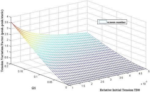
Fig. 3Dynamic tension variation with different dimensionless parameter Ω1 and Ω2 as odd number n
4. Illustrative examples
A numerical approach to calculate the dynamic tension of the galloping conductors is proposed as illustrative examples to validate the above formula [20].
A full multi-span finite element iced transmission line model is used to describe the galloping phenomena and calculate the horizontal tension variance caused by galloping. The line is simulated by six-degree-of-freedom (6-DOF) curved beam element.
Without lost of generality, a typical conductor ACSR GL/G1A-240/30-24/7 is selected in this analysis. The physical parameters used in the simulation are listed in the Table 1.
Table 1Parameters employed to simulate galloping
Parameters | Units | For line in example |
Axial rigidity | N | 2.78×10⁷ |
Horizontal component of tension | N | 19550 |
Diameter of bare conductor () | mm | 21.6 |
Damping ratio in the direction | 0.008 | |
Mass per unit length | kgm–1 | 0.921 |
Iced conductor shape | D-shape | |
Ice thickness (()/2) | mm | 10 |
Static off-set angle () | º | 10 |
Fig. 4A schematic for D-shape iced conductor, L is iced conductor section width, R is diameter of bare conductor, θ is static off-set angle and UZ is wind velocity
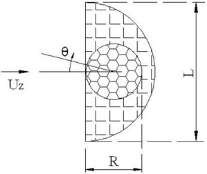
Fig. 5Lift, drag and moment coefficients of the D-shaped conductor used in example
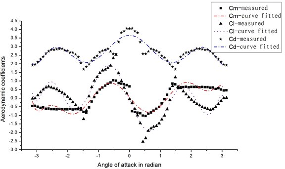
Fig. 6Comparison of theoretical predictions with numerical simulated data
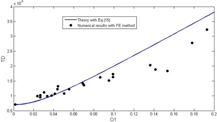
a) Dimensionless tension maximum with different dimensionless parameter as even order modes
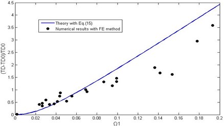
b) Dynamic tension variation factors with different dimensionless parameter as even order modes
Fig. 7Comparison of theoretical predictions with numerical simulated data
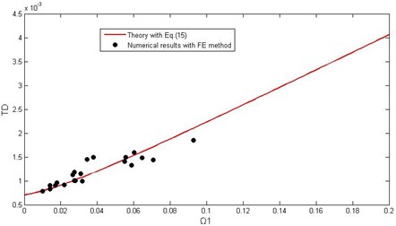
a) Dimensionless tension maximum with different dimensionless parameter as odd order modes
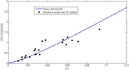
b) Dynamic tension variation factors with different dimensionless parameter as odd order modes
The ice accretion is an important inducement for conductor galloping. Eccentric ice coated on the conductor has the effect to modify the original conductor’s cross sectional shape such that it becomes aerodynamically or aeroelastically unstable to excite galloping. Based on existing field observations and researchers, D-shape iced conductor is the most sensitive to excite galloping than other familiar eccentric ice shapes. So in this analysis, a typical D-shape iced conductor model is selected and a schematic is shown in Fig. 4.
The quasi-steady aerodynamic loads were measured in a wind tunnel for this D-shape iced conductor and they are given in Fig. 5. And the relevant polynomial fitting curves to the aerodynamic coefficients are also shown in Fig. 5.
The different conductor galloping characteristics are obtained by using different horizontal distance between adjacent towers, different wind velocities and different wind load distributions.
Numerical and theoretical values of this example are compared in Fig. 6 as the number of galloping loops is even order and Fig. 7 as it is an odd order. Fig. 6(a) gives the dimensionless tension maximum against different parameter . From this figure, it is perfect agreement between numerical and theoretical values when is on the small side. And the numerical simulation data of tension maximum fall consistently below the theoretical values when is greater than 0.14. These differences are up to 30 percent. And the great discrepancies between numerical simulation and theoretical calculation are possibly because that theoretical analysis does not consider plastic deformation on conductors and influence of adjacent spans. The larger indicates greater galloping amplitude when the span length is limited. Especially with the extremely great amplitude galloping condition, conductor plastic deformation and adjacent span action will play a more important role, which makes the galloping tension maximum obtained by theoretical calculation will be greater than by numerical simulation. And Fig. 6(b) gives tension variation factor against different parameter , and it shows the same trend with the Fig. 6(a).
Fig. 7(a) gives dimensionless tension maximum against different parameter obtained by numerical simulation and theoretical calculation respectively, which shows the perfect agreement between numerical and theoretical results. And in Fig. 7(b) the numerical simulated and theoretical calculated tension variation factors against different parameter are compared, which shows that it is an agreement when is less than 0.1.
5. Conclusions
Dynamic tension variation caused by the conductor galloping has a major impact on design and stable operation for the overhead transmission lines. The formula to calculate the dynamic tension variation caused by the conductor galloping is derived clearly by the energy balance method presented in this paper. And two parameters and to influence the dynamic tension are proposed by the dimensionless analysis. The obtained results could be summarized as follows.
1) Dimensionless tension variation maximum is only related to the initial tension and two parameters and . With increasing of values for these parameters, the tension variation maximum will augment. is more important whether the number of galloping loops is even or odd, and has the influence only when the number of galloping loops is odd.
2) When Eq. (10) and Eq. (12) are satisfied, the popular expression obtained by the length variation method can be deduced from the formula derived using the energy balance method by the series expansion. It means that Eq. (11) is available only for small values of and .
3) The tension variation maximum by the conductor galloping can go up to 3-4 times as large as the initial tension for the extreme cases.
4) This theoretical analysis does not consider the plastic deformation on conductors and the influence of adjacent spans. And as an important parameter, wind can be considered implicitly by galloping amplitude in dimension parameter .
References
-
CIGRE Study Committee B2 WG11. State of the art of conductor galloping. Electra No. 322, 2007.
-
Hughes D. T. The dynamic loading of overhead conductors on 11kV lines. International Conference on Design and Construction, Theory and Practice, London, 1988, p. 178-181.
-
Yang F. L., Yang J. B., Zhang Z. F. Unbalanced tension analysis for UHV transmission towers in heavy icing areas. Cold Regions Science and Technology, Vol. 70, 2012, p. 132-140.
-
Meng X. B., Wang L. M., Hou L., Fu G. J., Sun B. Q., MacAlpine M., Hu W., Chen Y. Dynamic characteristic of ice-shedding on UHV overhead transmission lines. Cold Regions Science and Technology, Vol. 66, 2011, p. 44-52.
-
Roshan Fekr M., McClure G. Numerical modeling of the dynamic response of ice-shedding on electrical transmission lines. Atmospheric Research, Vol. 46, Issue 1-2, 1998, p. 1-11.
-
Gurung C. B., Yamaguchi H., Yukino T. Identification of large amplitude wind-induced vibration of ice-accreted transmission lines based on field observed data. Engineering Structures, Vol. 24, Issue 2, 2002, p. 170-188.
-
Shehata A. Y., Damatty A. A. E., Savory E. Finite element modeling of transmission line under downburst wind loading. Finite Elements in Analysis and Design, Vol. 42, Issue 1, 2005, p. 71-89.
-
Zhu K. J., Li X. M., Di Y. X., Liu B. Asynchronous swaying character and prevention measures in the compact overhead transmission line. High Voltage Engineering, Vol. 36, Issue 11, 2010, p. 2717-2723.
-
Lilien J. L., Wang J., Chabart O., Pirotte P. Overhead transmission lines design. Some mechanical aspects. International Conference on Power System Technology, Beijing, 1994, p. 18-21.
-
Liu C. L., Zhu K. J., Liu B., Di Y. X. Dynamic tension of iced conductor galloping. Journal of Vibration and Shock, Vol. 31, Issue 5, 2012, p. 82-86.
-
Zhu K. J., Liu C. Q., Ren X. C. Analysis on dynamic tension of conductor under transmission line galloping. Electric Power, Vol. 38, Issue 10, 2005, p. 40-44.
-
Wang S. H., Jiang X. L., Sun C. X. Characteristics of icing conductor galloping and induced dynamic tensile force of the conductor. Transactions of China Electrotechnical Society, Vol. 25, Issue 1, 2010, p. 159-166.
-
Baenziger M., James W., Wouters B., Li L. Dynamic loads on transmission line structures due to galloping conductors. IEEE Transactions on Power Delivery, Vol. 9, Issue 1, 1994, p. 40-49.
-
Naif B. Almutairi, Zribi M., Abdel-Rohman M. Lyapunov-Based control for suppression of wind-induced galloping in suspension bridges. Mathematical Problems in Engineering, Vol. 2011, 2011, p. 1-23.
-
Barbieri N., Junior O. H. S., Barbieri R. Dynamical analysis of transmission line cables. Part 1-linear theory. Mechanical System and Signal Processing, Vol. 18, 2004, p. 650-669.
-
Barbieri R., Barbieri N., Junior O. H. S. Dynamical analysis of transmission line cables. Part 3-Nonlinear theory. Mechanical System and Signal Processing, Vol. 22, 2008, p. 992-1007.
-
McClure C., Lapointe M. Modeling the structural dynamic response of overhead transmission lines. Computers and Structures, Vol. 81, 2003, p. 825-834.
-
Lilien J. L., Havard D. G. Galloping data base on single and bundle conductors prediction of maximum amplitudes. IEEE Transactions Power Delivery, Vol. 15, Issue 2, 2000, p. 670-674.
-
Havard D. G. Dynamic loads on transmission line structures during galloping. The International Workshop on Atmospheric Icing of Structure, Brno, Czech Republic, 2002.
-
Zhu K. J., Liu B. A numerical simulation method on galloping of transmission lines. Transmission and Distribution Conference and Exposition: Asia and Pacific, Seoul, 2009.
About this article
The authors are grateful for financial support from the National Natural Science Foundation of China (51008288).
