Abstract
High speed turn-milling is regarded as the milling of a curved surface while rotating the workpiece around its centre point, which combines effectively the advantages of both turning and milling, wherein allows for good metal removal with the difficult-to-cut thin-walled workpieces in aviation. The objective of the present work is to study chatter stability of thin-walled blade by high-speed turn-milling in cutting condition. The dynamic model and the stability critical condition determined by the relative dynamic characteristics between cutter subsystem and blade subsystem are put forward. Aiming at the small-stiffness frequency response characteristics of thin walled structures, the stability critical domain is predicted based on the high-order dynamic behavior of the multi-DOF system. It can be shown that the chatter condition in turn-milling is closely related to both cutter speed and depth of cut, besides cutter geometry, engagement conditions, frequency response function, material property of workpiece and so on. Based on chatter stability simulation model to access 3D chatter stability lobes of high-speed turn-milling machining blades. This conclusion provides a theoretical foundation and reference for the orthogonal turn-milling mechanism research.
1. Introduction
As a newly emerging cutting technology, turn-milling makes use of the advantages of turning and milling, which both workpiece and cutting tool are given rotary motion simultaneously, in particular, eccentric machining. The advanced machining method can make the machining accuracy, processing efficiency to be required. So it enjoys the advantages of turning and milling and excels at machining revolving workpieces, like crankshafts or camshafts [1-2]. Actually, its strengths are far more than this. Owing to intermittent cuts and simultaneous rotations of tools and workpieces, it keeps low thermal stresses, lowers cutting forces and has good removal rates. As the blade is thin-wall part and easily deformed in load condition, the chatter is occurred in high-speed turn-milling process. If the cutting force is too large, it will cause large blade deformation, and easily lead to poor surface results from instability, so that the workpiece is difficult to achieve processing requirements [3-5].
There are some literature researches on chatter stability in general turning or milling. Altintas [6-7] were presented single-degree-of-freedom, and multi- degree-of-freedom machining chatter, as well as a variety of processing methods stability chatter, ball milling, and the three modes have an impact on the direction of the cutting thickness, so that the two-dimensional theory be extended to three-dimensional chatter stability. Pogacink [8] has researched turn-milling dynamic stability by using cutting parameters optimization. He proved turn-milling machining surface quality better than normal turning. Thevenot [9] has presented the integration of dynamic behavior variations in the stability lobes method: three lobes construction and application to thin-walled part. These computed results are compared with real experiments of down-milling of thin-walled structures. Budak [10-14] has proposed the variable pitch cutters can be used to suppress chatter in milling of these extremely flexible components. And then, he has studied the workpiece dynamics affect stability in machining of flexible parts and presented a methodology for prediction of in process workpiece dynamics based on a structural dynamic modification by using the FE model of the workpiece. Song [15] has proposed the method for predicting simultaneous dynamic stability limit of thin-walled workpiece high-speed milling process, which takes into account the variations of dynamic characteristics of workpiece reprehensive of a typical industrial application by finite element method. Tang [16] has studied the machining stability in milling of the thin-walled plate and develops a three dimensional lobe diagram of the spindle speed, axial, and radial depth of cut. Through the three-dimensional lobe, it is possible to choose the appropriate cutting parameters according to the dynamic behavior of the chatter system. Moreover, this paper studies the maximum material removal rate at the condition of optimal pairs of the axial and radial depth of cutting. Bravo [17] has proposed considering such applications and suggested a method for obtaining a 3D stability lobe to cover all the intermediate machining stages.
This paper is divided into four main sections; the first, entitled the principle of high-speed turn-milling machining blades, will introduce the basic motions in turn-milling process. The second section, the relative transfer function of tool-blade system, will discuss transfer function blade and cutter respectively, and then the modal test was conducted. The third part, the calculation model of stability lobes and simulation process, will built machining stability model based on the relative transfer function, the simulation flow process and so on. The next part, the influence analysis of technological parameters on chatter stability, will analyze chatter stability relative to both cutter speed and depth of cut, besides cutter geometry, engagement conditions, and frequency response function. Finally, in section four, some conclusions from this study are given.
2. The principle of high-speed turn-milling blades
Turn-milling involves four basic motions including rotation of cutter, rotation of workpiece, axial feed, and radial feed of cutter, as shown in Fig. 1. High-speed milling machining blades is not simply the turning and milling processing methods into a single machine for processing blade, but the use of turn-milling motion to accomplish complex surface machining blades. The main cutting motion is rotary motion of ball milling, the speed of ball milling rotation and blades rotation together determine the cutting speed. The rotational speed of the ball cutter is the main role in the whole cutting process, so in some high-speed, ultrahigh-speed turn-milling machining can even ignore the rotation speed of the blades. Rotation speed of the blades, ball milling axial velocity and radial feed of cutter those three basic rates together determine the total turn-milling machining cutting blade velocity, obviously, and the main role of the total velocity is the rotation speed of the blades.
Fig. 1Turn-milling blade principle diagram
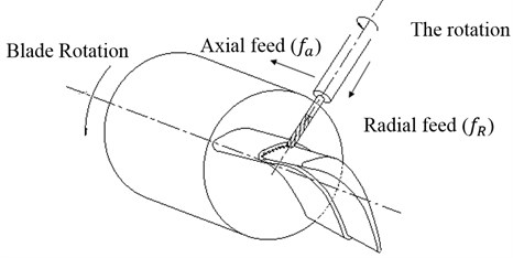
With respect to the blade of this part has complex surface which is difficult to machine, only one direction of feed for processing is difficult to processing requirements, therefore its processing need to feed from two directions. Due to the high-speed turn-milling is a composite of turning and milling, it is easy to automatically except crumbs in the process, meanwhile the tool and the chip contact time is shorter so the tool can obtain good heat dissipation. This will improve the surface quality of processing. Several cutting edges are in contact with the workpiece at all times during the cutting period and the transfer of heat from the machining zone by the chips keep the workpiece temperature relatively low preventing thermal deformations, so high surface finish and reducing tool wear are generated in such operations due to chip formation the intermittent cutting process. In addition, good chip removal has also been achieved due to short chip length and compared with turning. Because of quenching time for cutting edges, the intermittent cutting and short chips are formed in orthogonal turn-milling process.
3. The relative transfer function of tool-blade system
The frequency response function is expressed for workpiece – tool subsystem in one degree of freedom:
where is stiffness (N/mm2), is damp ratio, is frequency (Hz).
The frequency response function is expressed for tool subsystem in multi-degrees of freedom as follows:
Similarly, the workpiece subsystem frequency response function is given:
To study the two subsystems of tool and workpiece must be studied on the transfer function in the same direction, so three directions transfer functions are established in space coordinate system. The transfer functions of tool are expressed in , and direction as follows:
where, and are respectively the real and imaginary parts of the system transfer function of the tool in , and direction. is the displaced direction of tool subsystem. is the force direction of tool subsystem.
The transfer functions of workpiece in , and direction are as follows:
where, and are respectively the real and imaginary parts of the system transfer function of the blade in , and direction. is the displaced direction of blade subsystem. is the force direction of blade subsystem.
For the tool subsystem and blade subsystem, the force values are same and the force directions is opposite interaction. After the analysis of the transfer function, the forces in , and direction are expressed as follows:
The relative movement of tool subsystem and blade subsystem is the addation of displacements in , and direction, so the two subsystems move away from each other due to the action of the cutting force. The absolute displacements are given as follows:
The relative transfer functions between the tool and the blade are obtained from Eq. (4)-(7) and analyzed as:
That is to say, the components of the Relative FRF are the addition between the tool’s FRF and the FRF of the workpiece in , and directions. The resulting FRF will be used for the calculation of the lobe diagram.
The difference between the transfer function of the relative movement with respect to the treatment of the tool’s and blade’s transfer functions as two independent entities seems obvious. For the transfer function of tool and blade, the modal test is conducted in 5-axis machining center. The diameter of cutter is 16 mm. There are some equipment as follows: 1) modal testing and analysis software Cut/Pro; 2) USB Carrier I/O-9233; Accelerometer sensor8778a500 (Sensitivity 10.00 mV/g); Hammer type 9722a500 (Sensitivity 10.00 mV/g); Sampling Rate (Hz): 50000; Frequency Range: 50-5000; Transfer function: Displacement-Force.
Fig. 2The modal test in 5-axis turn-milling center
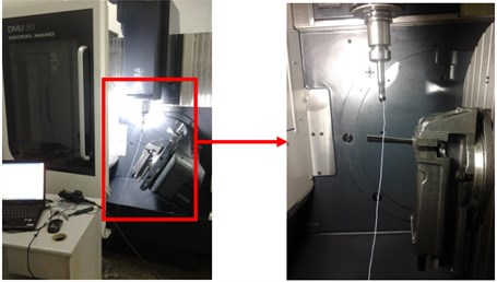
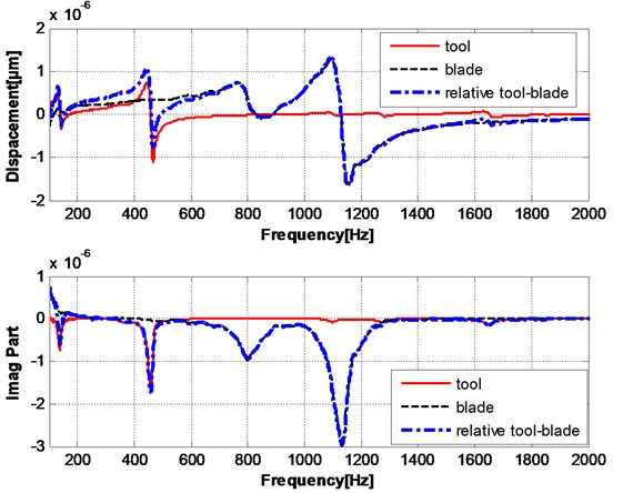
Fig. 3 the amplitude and phase diagram (Bode diagram) of the multi-modes transfer function tool subsystem, the multi-modes transfer function of workpiece sub-systems and system transfer function (relative to the transfer function of the system). It can be shown that the transfer function of the structure of a processing system depends on the relative relationship between the two subsystems. A first-order natural frequency equal to the natural frequency between the lowest among all the natural frequency, the last-order natural frequency is equal to the natural frequency between the highest natural frequency, that is the natural frequency of the system is relatively low to the high order by sequentially increased number order.
Fig. 3Relative transfer function of multi-mode in turn-milling
4. The calculation model of stability lobes and simulation process
After the modeling and simulation of the relative transfer function, the theory calculation of lobe diagram analytically is carried out in the frequency domain. In the stability model, the dynamic milling forces are expressed as follows:
where, [] is time invariant but immersion dependent directional cutting coefficient matrix. The dynamic milling forces are in , and directions; is the dynamic displacement vector which can be expressed as the difference between the displacements at current time and one tooth period:
where, is the tooth period. The regenerative vibration vector can be expressed as follows:
where the transfer function matrix identified at the cutter-workpiece contact zone:
The chatter stability of the system is determined by the characteristic equation of the three dimensional dynamic milling system. The complex eigenvalue is given by:
The critical axial depth of cut at chatter frequency:
Since must be a real number, and the imaginary part of the Eq. (13) must vanish. The given the chatter frequency, the chatter limit in terms of the axial depth of cut can directly be determined from Eq. (13):
where is phase shift between inner and outer modulations (present and previous vibration marks). The spindle speed () is simply calculated by finding the tooth passing period () and corresponding spindle speed.
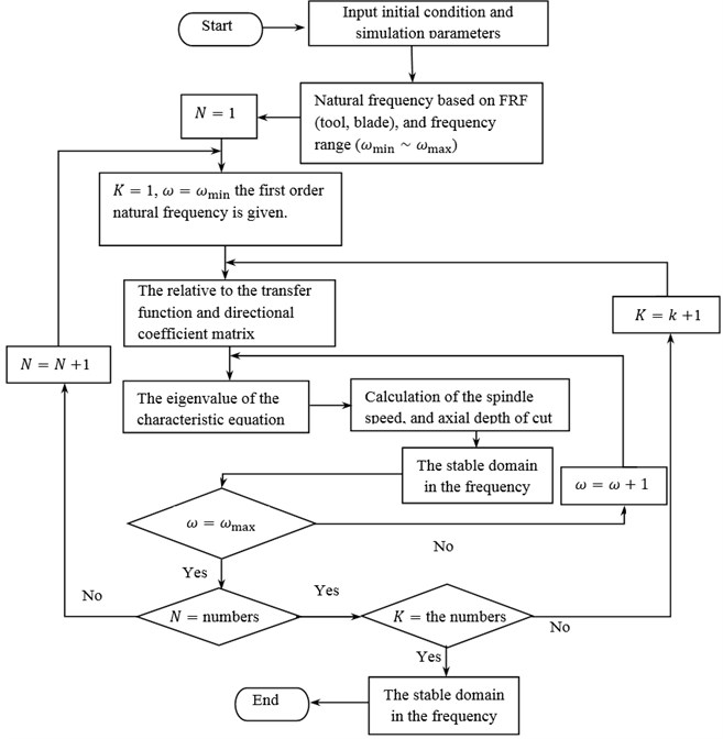
The behavior of system is used for chatter stability as shown in Fig. 4. The detail steps of calculation lobe diagram process are are follows.
Fig. 4Flow chart for simulation of chatter stability
5. Influence analysis of technological parameters on chatter stability
5.1. The influence of radial width and tool diameter ratio on chatter stability
The three-dimensional chatter diagram is simulated to analyze influence law in different technological parameters. In maintaining the cutting tool geometry parameters unchanged, only change the relative position of the blade axial the results of three-dimensional chatter stability limit diagram as shown in Fig. 5. In addition to maintaining the tool geometry parameters under radial cutting machining width and process parameters of tool diameter unchanged. The ratio between different radial machining width and tool diameter () is simulated by changing the width of. Finally, get corresponding comparison diagram between high-speed turn-milling machining systems three-dimensional chatter limit diagram with two-dimensional diagram under different values of . It can be seen in Fig. 6 that the radial width of the machining and tool diameter ratio increases, the corresponding maximum chatter of cutting depth also decreases. The reason results from the radial width of the machining and the tool diameter ratio changes, resulting in the tool-workpiece system relative modal parameters also changes, thereby affecting the minimum limit stability of the system. The perspective of its three-dimensional lobe diagram is simulated as follows: a narrow opening in 0 condition. The stable limit is minimum value; close to wide ratio 1, the stability limit increases.
Fig. 53D graph for the effect of ae/D on chatter stability
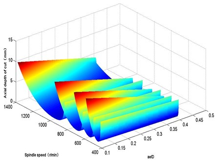
Fig. 6Effect of ae/D on chatter stability
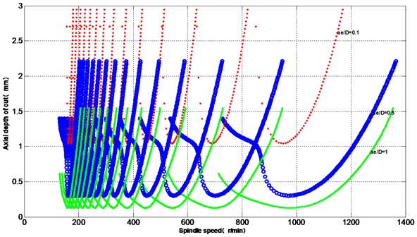
It can be shown that in conditions permit, the processing required to ensure that the case should try to use a smaller radial machining width and tool diameter ratio of the turn-milling process, which avoids the occurrence of chatter, and will get better surface quality, but the process is not very efficient.
5.2. The influence of ball inclination angle on chatter stability
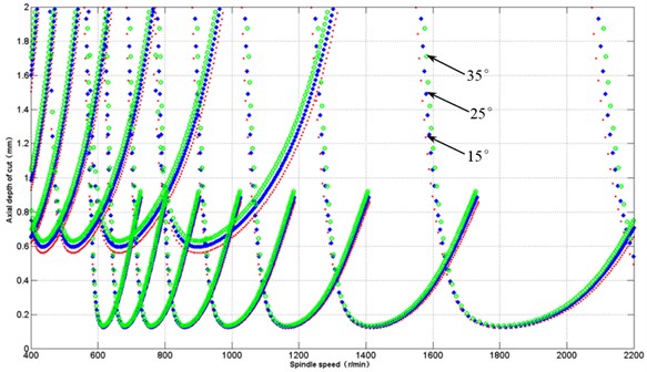
In addition to maintaining the tool inclination angle under the geometric parameters of machining and the same cutting process parameters, the effect of inclination (15°, 25°, 35°) on chatter stability is simulated. It can be obtained that corresponding comparison diagram between high-speed turn-milling machining systems stability limit diagram under different inclination values. It can be seen when the ball milling inclination increases, the corresponding chatter limit depth of cut also increases, the reason is that due to the tooling inclination angle changes, resulting in the tool-blade relative modal system parameters changes, thereby affecting the minimum stability limit of the system. The processing of all the different angle of each lobe corresponding to inclination angle will open the same size, the same with degree of intensity distribution, which avoids the occurrence of chatter, but should not blindly increase the processing inclination angle, the ball-cutter radius, length, and processing space and so on should also to be considered.
Fig. 7Effect of inclination angle on chatter stability
5.3. The influence of tool radius on chatter stability
In addition to maintaining the tool radius under the geometric parameters of machining and the same cutting process parameters, the effect of cutter radius on chatter stability is simulated. It can be seen that the ball milling cutter radius increases, the corresponding chatter limit depth of cut is also decreased, which different tool radius results in different tools modal parameters, and thus impact on system minimal stability limit. As can be shown in Fig. 8 and Fig. 9, each lobe ball milling of all different radius will moves slowly under the overall radius increase, but the same size and shape of stability lobes. It can be shown that the case should try to use a smaller radius ball milling machining turn-milling cutter, which avoids the occurrence of chatter, and improve processing quality.
5.4. The influence of the radial cutting depth on chatter stability
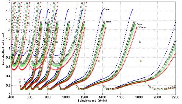
Radial cutting depth is an important factor, which will effect on stability lobe in high-speed turn-milling process. In the unchanged machining parameters, the stability limit is simulated in different radial cutting depth (3 mm, 4 mm, 4.5 mm, and 5.5 mm). As can be seen that the radial cutting depth increases, the corresponding stability limit of cutting depth is less, which results from the different tool-blade system modal parameters. As shown in Fig. 10, in addition to each of all blades under different radial cutting depth will increase as the radial cutting depth as a whole moving up, will also tiny moving towards small speed, but the same size and shape of stability lobes. It should try to use the smaller radial cutting depth for turn-milling, which can avoid of chatter phenomenon, and improve the quality of processing, but the efficiency will be decreased.
Fig. 8The effect of tool radius on chatter stability
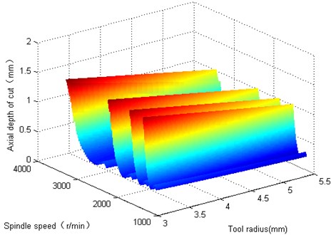
Fig. 9Effect of tool radius on chatter stability
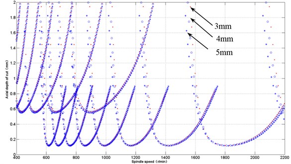
Fig. 10Effect of radial cutting depth on chatter stability
6. Conclusions
– The chatter condition in turn-milling is closed relative to both cutter speed and depth of cut, besides cutter geometry, engagement conditions, frequency response function, material property of workpiece and so on.
– The dynamic model and the stability critical condition determined by the relative dynamic characteristics between cutter subsystem and blade subsystem are proposed to obtain the reasonable and accurate stability domain.
– When the increase of radial width, cutter radius and radial cutting depth, the corresponding maximum chatter of cutting depth also decreases. So when conditions permit, the processing required ensuring that the case should try to use a smaller radial machining width and tool diameter ratio of the turn-milling process, which avoids the occurrence of chatter, and will get better surface quality, but the process is not very efficient.
– When the ball milling inclination angle and cutter teeth increases, the corresponding chatter limit depth of cut also increases. It can be seen that the case should try to use a lager inclination angle to turn-milling machining process, which avoids the occurrence of chatter, but should not blindly increase the processing inclination angle; the ball-cutter radius, length, and processing space and so on should also be considered.
References
-
Skoric S., Udiljak T., Ciglar D. Study of the suitability of the machining of rotating surfaces. Transactions of Famena, Vol. 32, Issue 2, 2008, p. 69-83.
-
Niroomand M. R., Forouzan M. R., Salimi M. Frequency analysis of chatter vibrations in tandem rolling mills. Journal of Vibroengineering, Vol. 14, Issue 2, 2012, p. 852-865.
-
Budak E., Çomak A., Öztürk E. Stability and high performance machining conditions in simultaneous milling. CIRP Annals-Manufacturing Technology, Vol. 62, Issue 1, 2013, p. 403-406.
-
Biermann D., Kersting P., Surmann T. A general approach to simulating work-piece vibrations during five-axis milling of turbine blades. CIRP Annals – Manufacturing Technology, Vol. 59, 2010, p. 125-128.
-
Kersting P., Biermann D. Modeling techniques for simulating work-piece deflections in NC milling. CIRP Journal of Manufacturing Science and Technology, Vol. 7, 2014, p. 48-54.
-
Altintas Y., Stepan G., Merdol D. Chatter stability of milling in frequency and discrete time domain. Annals of the CIRP, Vol. 53, Issue 1, 2008, p. 35-44.
-
Altintas Y., Eynian M., Onozuka H. Identification of dynamic cutting force coefficients and chatter stability with process damping. CIRP Annals-Manufacturing Technology, Vol. 57, 2008, p. 371-374.
-
Pogacink M., Kopac J. Dynamic stabilization of the turn-milling process by parameter optimization. Journal of Engineering Manufacture, Vol. 214, Issue 2, 2000, p. 127-135.
-
Thevenot V., Arnaud L., Dessein G. Integration of dynamic behavior variations in the stability lobes Method: 3D lobes construction and application to thin-walled structure milling. International Journal of Advanced Manufacturing Technology, Vol. 27, Issue 7, 2006, p. 638-644.
-
Budak E. Improving productivity and part quality in milling of titanium based impellers by chatter suppression and force control. Annals of the CIRP, Vol. 49, Issue 1, 2000, p. 31-36.
-
Budak E., Tunc L. T., Alan S., Ozguven H. N. Prediction of workpiece dynamics and its effects on chatter stability in milling. CIRP Annals-Manufacturing Technology, Vol. 61, Issue 1, 2012, p. 339-342.
-
Budak E., Ozturk E., Tunc L. T. Modeling and simulation of 5-axis milling processes. CIRP Annals-Manufacturing Technology, Vol. 58, 2009, p. 347-350.
-
Erhan Budak, Taner Tunc, Salih Alan Prediction of work-piece dynamics and its effects on chatter stability in milling. CIRP Annals-Manufacturing Technology, Vol. 61, 2012, p. 339-342.
-
Erdem Ozturk, Erhan Budak Dynamics and stability of five-axis ball-end milling. Journal of Manufacturing Science and Engineering, Vol. 132, 2010, p. 1-13.
-
Song, Q., Ai X., Tang W. Prediction of dynamic stability limit of time-variable parameters system in thin-walled workpiece high-speed milling processes. The International Journal of Advanced Manufacturing Technology, Vol. 55, Issue 9-12, 2011, p. 883-889.
-
Tang A., Liu Z. Three-dimensional stability lobe and maximum material removal rate in end milling of thin-walled plate. International Journal of Advanced Manufacturing Technology, Vol. 43, Issue 1-2, 2009, p. 33-39.
-
Bravo U., Altuzarra O., et al. Stability limits of milling considering the flexibility of the workpiece and the machine. International Journal of Machine Tools and Manufacture, Vol. 45, 2005, p. 1669-1680.
-
Liang R., Ye W. Thin-walled parts to predict and verify the stability of high-speed milling. Journal of Mechanical Engineering, Vol. 45, Issue 11, 2009, p. 147-148, (in Chinese).
About this article
This work was supported by (National Natural Science Foundation of China) NSFC (51105072) and (51475087), supported by Fundamental Research Funds for the Central Universities (N130403010).
