Abstract
Rotordynamic instability and vibration due to fluid forces within annular seals are well-known phenomenons that can occur in pumps as well as in turbines. Traditional theoretical predictions for the fluid reaction forces and equivalent dynamic characteristics of annular seals are computationally efficient compared with CFD method. Exit pressure loss coefficient is one of the main factors that influence the precisions of theoretical analysis. In this paper, exit pressure recovery coefficients at three different static eccentricity ratios under different operating conditions are investigated using CFD method. The numerical result shows that exit coefficient increases exponentially with the ratio of circumferential velocity to axial velocity at all these three eccentricity ratios. Besides, an analysis method for annular plain seals with the introduction of exit pressure recovery coefficient varied with operating conditions is proposed based on the previous analysis results. Comparisons are made between theoretical predictions calculated by the two methods with and without exit coefficient over a wide range of pressure drops and running speeds. The result suggests that damping coefficients are much more sensitive to the change of the exit boundary conditions compared to stiffness coefficients. In addition, the new prediction results of cross-coupled stiffness and direct damping coefficient show relatively smooth change with the increase of velocity ratio than the previous results.
1. Introduction
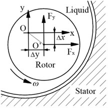
High-pressure annular seals are primarily used to control the leakage in turbomachines, especially in multi-stage centrifugal pumps such as boiler feed pumps and other heavy duty pumps. Fig. 1 shows three typical annular seals in multi-stage centrifugal pumps, i.e. wear-ring seal, interstage seal and balance-discharge seal. Wear-ring seals restrict the leakage along the front side of the impeller, while interstage seals and balance-piston seals restrict flow along the shaft between stages. The enlarged clearances, combined with high rotating speed, large pressure differences and low viscosity liquid make the flow in the clearance paths highly turbulent. As illustrated in Fig. 2, when the pump begins to operate with a rotating speed of , the highly turbulent flow leads to pressure differences in both and directions which will act on the rotor surface. Similar to the ‘Oil whip’ phenomenon in journal bearings, these pressure differences force the rotor to move off the original center ‘O’ and the eccentric motions in turn produce larger forces in both directions, i.e., and . Hence, a similar amount of rotor support stiffness and damping can be provided by these forces which is called Lomakin effect.
Fig. 1Typical annular seals in multi-stage centrifugal pumps
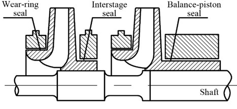
Fig. 2Fluid forces acting on annular seals
In a series of publications, researchers have explained the considerable influence of seal forces on the vibration and other rotordynamic behaviors of pumps [1, 2]. With the increasing demands for pumps operating at higher speeds and pressures, the possibility of instability and vibrations resulting from lager seal forces are raised. Besides, rotordynamic problems generally become apparent with the abrasion level of annular seals. Therefore, the dynamic characteristics of annular seals must be precisely calculated for more accurate predictions of pump vibrations and dynamic behaviors.
Most previous studies on the dynamic characteristics of liquid seals mainly included three aspects: experimental studies, theoretical analyses combined with numerical solutions and CFD simulations. Childs D. W. [3] performed a finite-length analysis on the dynamic characteristics of plain annular seals based on Hirs’ lubrication equations. Nelson and Nguyen [4, 5] developed a new solution using Fast Fourier Transforms (FFT) to find out the effects of eccentricity on rotordynamic coefficients of plain annular seals. Tae-woong Ha et al. [6] developed a solution procedure to solve the dynamic performances of floating ring seals using Nelson and Nguyen’s method. H. Ysu and Brennen [7] developed evolutionary vorticity equations and total pressure equations for turbulent flow in fluid-filled annuluses and suggested a numerical solution for the flow field by iterating between these equations and a Poisson-like equation. Duan Wenbo et al. [8] used the bulk-flow model with a steepest-descent method to calculate the static and dynamic characteristics of floating ring seals, which is more efficient compared to the FFT method. Marquette et al. [9] provided experimental results of the eccentricity effects on the rotordynamic coefficients over a wide range of static eccentricity ratios. Bradley [10] presented the experimental and theoretical rotordynamic coefficients of straight smooth annular gas seals under different operating conditions. Qinglei Jiang et al. [11] used a numerical integration and finite difference method to study the influence of annular seal flow on the transient response during the start-up period of a single rotor pump and a three-stage pump. Tae-wong Ha and Bokseong [12] studied the rotordynamic coefficients of a plain eccentric annular seal using a 3D CFD code and RNG - turbulent model. Alexandrina et al. [13, 14] studied the rotordynamic coefficients for a damped water seal of large aspect ratios (/ above 1.0) with complex geometry using SST turbulence model.
In most theoretical analyses, dynamic characteristics of annular seals are calculated using governing equations of the fluid flow within the seals combined with perturbation solutions. Zeroth-order and first-order perturbation equations of the governing equations are developed by an expansion in the eccentricity ratio. Steady-state velocities and leakage rates of the seals are solved first, using zeroth-order equations. Then, dynamic characteristics of annular seals are figured out using first-order equations combined with inlet and exit boundary conditions which are defined in terms of the inlet-loss and exit-recovery coefficients respectively.
For the last three decades, researchers and engineers have done a lot of work for better accuracy of the inlet and exit coefficient values of annular water seals. Stampa [15] demonstrated that exit coefficient was a function of axial Reynolds number for liquid annular seals with a finite exit chamber. The measurements by Weber [16] showed that the exit coefficient varied as a function of the ratio of round off radius to seal clearance similar to a diffuser. Florancic [17] documented that compared with the experimental results, the best predicting results were achieved when the exit coefficient was set to 0.85 and 0.7 for two different seals. Childs D. W. [18] introduced exit coefficient to the rotordynamic characteristics calculation of a taper smooth annular seal and the calculation results showed that a change of the exit loss coefficient from 1.0 to 0.5 approximately doubled the direct stiffness of a specific seal. White [19] fully studied the exit coefficients of turbulent flow that flowing from a definite chamber into three different conical diffusers with cone angles of 5°, 20° and 40° respectively. Eskild Storteig [20] studied the exit coefficient using two-dimensional CFD method and experimental method under different axial Reynolds numbers and the rotating speeds. Boris Grigoriev [21] investigated the inlet loss coefficient for gas seals as a function of the inlet conditions using CFD method. Jiang Qinglei et al. [22] studied the influence of different annular channel sizes and boundary conditions on inlet pressure-loss coefficient of a three-dimensional concentric model using CFD method.
Though most of these present studies for annular seal coefficients are based on the small eccentric perturbation assumption, almost all the exit pressure recovery coefficient, or exit coefficient for short, used in the numerical solutions are experience factors measured under concentric conditions. In fact, orbital motion about an eccentric position is much more likely to occur in practice due to misalignment of the rotor during assembly and side loads acting on the rotating components. Besides, these factors are always the same even under different pressure drops and rotating speeds which is quite different from the real situation. Although there has been lots of related research on exit coefficients and on the dynamic characteristics at different eccentric ratios, the work about exit coefficients under a definite static eccentricity is scarce, especially under large eccentric ratios.
In this paper, exit coefficients at three different eccentricity ratios under different operating conditions are investigated using CFD method. An analysis procedure for annular plain seals with the introduction of exit recovery coefficient varied with operating conditions is developed and comparisons of the theoretical dynamic characteristics predicted by the two methods with and without exit coefficient are made.
2. Models and computational schemes
2.1. Geometry and grid
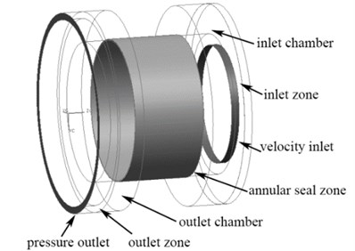
The computational model used here is the same as the model described by Eskild Storteig [20]. Fig. 3 and Fig. 4 illustrate the structure of the model seal and its hydraulic model for CFD calculation. As is shown in Fig. 4, the calculation model includes inlet zone, inlet chamber, annular seal zone, outlet chamber and the outlet zone. Inlet chamber and outlet chamber are used to stabilize the entrance and exit flow. The inner wall of the seal zone rotates about a definite eccentric center with a wide range of rotating speeds. Principal specifications and operating conditions of the model are listed in Table 1.
Fig. 3Geometric parameters of the model seal
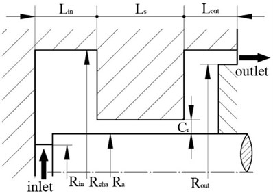
Fig. 43D hydraulic model for CFD calculation
As the exit coefficient calculation requires high quality mesh, all the components have been discretized by hexahedral grids using Gambit. A grid independence study using seven different sizes of grids is carried out and the results show that mesh convergence is obtained when the node number along the radial direction is more than 20 with a total mesh number of 1.98 million, as shown in Fig. 5.
Table 1Specifications and operating conditions of the hydraulic model
Geometric dimension | Value (mm) | Geometric dimension | Value (mm) |
Radius of the axis | 66.523 | Radial clearance | 1.026 |
Chamber outer radius | 95.049 | Seal length | 67.58 |
Inlet inner radius | 88.599 | Length of the inlet chamber | 24 |
Outlet inner radius | 56 | Length of the outlet chamber | 31 |
Computational scheme | |||
Axial Reynolds number | 5000/7500/10000/12500/15000/17500/20000 | ||
Rotating speed (rpm) | 500/1000/1500/2250/3000 | ||
Fig. 5Mesh independence check
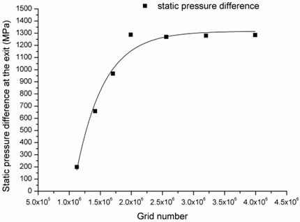
Fig. 6Mesh of the whole model
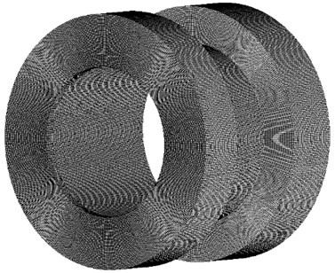
The appropriate number of mesh points for the simulation is determined by the preliminary simulation results. A mesh of 2.56 million elements and 7.79 million nodes is employed for the computational domain. In order to reduce the dimensionless wall distance () of the annular seal zone, local refinements are applied at this place, especially the positions near the rotating wall. Maximum values of for the models with three different eccentricity ratios are obtained under the highest pressure drop and rotating speed. The values are 83.4, 91.7, and 97.3 respectively. Fig. 6 shows the mesh assembly of the components.
2.2. CFD model and boundary conditions
The whirling, unsteady flow problem in the seal is transformed into a steady one by solving the three-dimensional eccentric flow field in a reference frame attached to the whirling rotor. And the commercial CFD code Fluent was employed to perform the simulation.
In the previous studies, most researchers used the standard - turbulence model with standard wall-friction approach. Recently, the Renormalization Group (RNG) - turbulence model, which is suitable to solve the problems of flow accompanied by separating or circulating flow, has been employed to analyze the seal performance by many researchers (Mazur et al., [23]; Shimada et al., [24]; Zhang W. F. et al., [25]). Hence, the RNG - turbulence model with enhanced wall treatment is used in this paper for calculating the flow characteristics inside the seal. The Semi-Implicit Method for Pressure-Linked Equations Consistent (SIMPLEC) is used for the discretized equations. Besides, second order upwind scheme is employed for the momentum, turbulent kinetic energy and dissipation rate. Velocity-inlet and pressure-outlet are used as the inlet and outlet boundary conditions respectively.
2.3. Measurement and validation against the published experimental results
Domm et al. [26] noted the pressure recovery at the seal exit as:
The equation shows that the pressure immediately inside the seal exit can be less than the exit pressure downstream of the seal . This phenomenon increases a seal’s direct stiffness. This paper focuses on the exit coefficients under different eccentricity ratios over a wide range of axial Reynolds numbers and rotating speeds. To validate the simulation approach and solver settings, comparisons are first made between the simulation results and the experimental results performed by Eskild Storteig [20].
Fig. 7Pressure transducer locations in the experiments conducted by Eskild Storteig
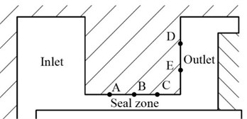
A complete test loop was built by Eskild. The maximum pressure was approximately 10 bar, and the rotating speed varied ranging from 0 to 2250 rpm. Water entered the test unit through a flexible hose. Inlet velocities vary directly with the required axial Reynolds number and rotating speed. Fig. 7 shows the locations of pressure transducers in this experiment. Three pressure transducers A, B and C were positioned in the seal paths with distances of 1/4, 1/2, and 3/4 of the seal length from the inlet. Static pressure right inside the exit could be figured out using difference method combined with the assumption that the pressure within the clearance changed linearly with the axial location. Two pressure transducers D and E located right on the inner surface of the outlet with distance of 1/3 and 2/3 of the chamber height from the exit. For each pressure tap in the clearance, 4 holes located with a 90° spacing around the circumference were drilled so that an average pressure could be measured for each axial location. The pressures right outside the exit were calculated based on the measured results of transducer D and E combined with flow field analysis. As for the CFD simulation, two recording surfaces are settled right inside and outside the exit in the distance of 0.01 mm. Thus, exit coefficient was obtained using Eq. (1) both in the experiments and the CFD simulations.
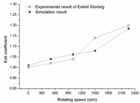
Fig. 8 shows CFD and experimental results of the exit coefficient at an axial Reynolds number of 104 with a series of rotating speeds. It can be seen that CFD model shows good agreement with the experimental data. Meanwhile, exit coefficient increases with the increasing rotating speed for both the experimental result and the simulation result. The error bars represent the uncertainty associated with experimental results. The main reason for the error is probably the linear assumption which will affect the accuracy of the static pressure value.
Fig. 8Comparison of computational and experimental results
3. Results and discussion
3.1. Exit coefficient change with axial Reynolds number
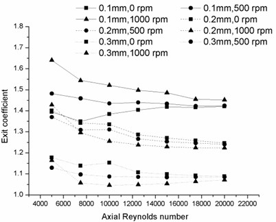
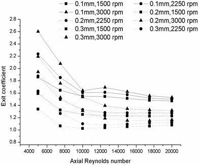
Fig. 9 shows the change of exit coefficient at eccentricity ratios of 0.1, 0.2 and 0.3 with axial Reynolds number in a range of rotating speeds. The coefficient decreases as the axial Reynolds number increases for almost all the cases. Note that when the axial Reynolds number is below 104, the change rate is comparatively large. However, the exit coefficients gradually tend towards a constant with the increase of axial Reynolds number when the axial Reynolds number is larger than 104. This constant value mainly depends on the eccentricity magnitude. It also can be seen that exit coefficients with smaller eccentricity ratios are more sensitive to the change of rotating speed.
3.2. Exit coefficient change with rotating speed
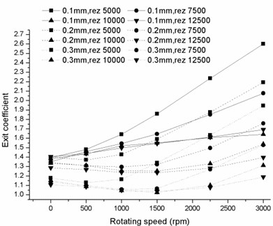
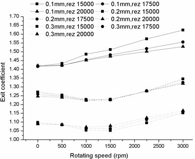
Fig. 10 illustrates the coefficient change versus rotating speed under a series of axial Reynolds numbers. Quite different from the curves shown in Fig. 9, there is no obvious plateau with the increase of rotating speed. The changing rates of the coefficient significantly increase with rotating speed, especially for the cases of 0.1 eccentricity ratio. Moreover, it is observed that the growth rate under the same operating conditions decreases with the increasing eccentricity ratio. Under the condition that the axial Reynolds number is above 15000, the exit coefficient value ranges under three eccentricities are totally isolated from each other.
Fig. 9Exit coefficient change with axial Reynolds number at rotating speed of a) 0 rpm, 500 rpm and 1000 rpm and b) 1500 rpm, 2250 rpm and 3000 rpm
a)
b)
Fig. 10Exit coefficient change with rotating speed Reynolds number of a) 5000, 7500, 10000, 12500 and b) 15000, 17500, 20000
a)
b)
Fig. 11Variation of exit coefficient with ratio of circumferential velocity to axial velocity
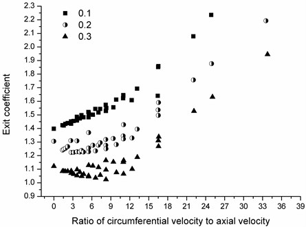
3.3. Exit coefficient change with the ratio of the circumferential velocity to axial velocity
According to the previous studies on inlet coefficients and analysis of suction 3.1 and 3.2, exit coefficient change with the ratio of circumferential velocity to axial velocity is also investigated. It is observed in Fig. 11 that the exit coefficient under small eccentricity is much more sensitive to the ratio than those of the larger ones. Exit coefficient is raised with the increasing ratio. The changing trends at the three eccentricity ratios are practically accordant. In addition, with the increase of eccentricity ratio, exit coefficients under lower ratios converge towards 1 which means that the pressure recovery phenomenon is getting less and less effective.
3.4. Effects of the exit coefficient on dynamic coefficients
Kündig [27] suggested a formula for the inlet loss depends on the swirl velocity:
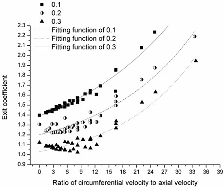
where, is the entrance loss at zero swirl. Therefore, it is assumed that a typical exponential function relation exits between exit coefficient and the ratio of circumferential velocity to axial velocity. 36 sets of calculation result at the eccentricity ratio of 0.1 are used to solve the fitting function. From the calculation results, we suggest the formula as below:
Comparisons for calculation results and three exponential fitting functions are shown in Fig. 12. The resultant values of the three exponential function coefficients are listed in Table 2.
Fig. 12Comparisons for exponential fitting function and the calculation result
Bulk-flow model with Blasius wall friction model is used to obtain the governing equations of the liquid in clearance paths including continuity, axial and circumferential momentum equations. Different from the traditional analysis method, exit coefficients changing with the exponential fitting functions are added to the boundary conditions. By substituting Eq. (3) into Eq. (1), new boundary condition with the introduction of exit coefficient changing with operating conditions is shown as below:
Table 2Resultant values of the fitting functions
Eccentricity ratio | |||
0.1 | 0.9514 | 0.4395 | 0.0403 |
0.2 | 0.9669 | 0.2344 | 0.0506 |
0.3 | 0.8856 | 0.1449 | 0.0603 |
Finite-length solution developed by Childs is used to solve the dynamic characteristics. Thereinto, zeroth-order and first-order motion equations satisfying the new boundary conditions are solved effectively using fourth order Runge-Kutta method and modified Euler method.
The effect of exit coefficient on dynamic characteristics of the model seal is also investigated. As the rotor eccentricity is usually set to 10 % of the radial clearance for most small-perturbation cases, the fitting function at the eccentricity ratio of 0.1 is used in the new procedure. An inlet loss of 0.1 is also selected which is a typical value for bulk-flow model calculations and the inlet swirl is assumed to be low.
3.4.1. Stiffness coefficient
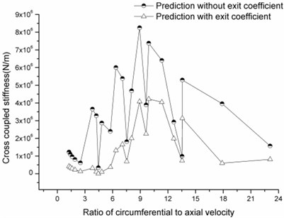
Fig. 13 and Fig. 14 provide direct stiffness and cross-coupled stiffness change versus the ratio of circumferential velocity to axial velocity. It is shown that prediction values of the direct stiffness calculated by the method with the exit coefficient are larger than those predicted by the method without the coefficient. However, cross-coupled stiffness predicted by the new method is slightly underpredicted compared to that calculated by the previous method. Both the direct stiffness and the cross-coupled stiffness predicted by these two methods follow the same trends with the changes in the ratio; namely, peaks and valleys occur at the same velocity ratios. It is observed that the cross-coupled stiffness prediction curve using the new method shows relatively smooth change with the increasing ratio, which is accordance with the actual case better and provide a larger safety margin in the structural design.
Fig. 13Direct stiffness versus ratio of circumferential velocity to axial velocity
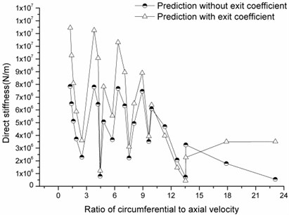
Fig. 14Cross-coupled stiffness versus ratio of circumferential velocity to axial velocity
3.4.2. Damping coefficient
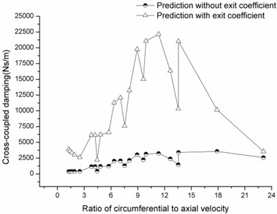
Compared to the stiffness, damping coefficient including the direct damping and the cross-coupled damping is more sensitive to the exit coefficient change as shown in Fig. 15 and Fig. 16. Though the variation tendencies of the damping coefficient with the increasing ratio predicted by the two methods are accordant, the prediction values under the same operating conditions differ a lot, especially for the cross-coupled damping coefficient.
Fig. 15Direct damping versus ratio of circumferential velocity to axial velocity
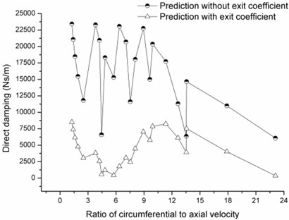
Fig. 16Cross-coupled damping versus ratio of circumferential velocity to axial velocity
4. Conclusions
In this paper, a three-dimensional model is employed to analyze the exit coefficient at three different eccentricity ratios under different operating conditions by CFD method. The numerical result shows that exit coefficient increases exponentially with the ratio of circumferential velocity to axial velocity at all the three eccentricity ratios. The relations of exit coefficient and the velocity ratio at the three eccentric ratios are established. And the fitting functions for the three different eccentricity ratios are obtained based on the calculation data.
A new analysis method for the dynamic characteristics of annular plain seals with the introduction of exit coefficient changing with rotating speed and pressure drops is proposed. Comparisons are made between the theoretical predictions of the stiffness and damping coefficients calculated by the two methods with and without exit coefficient over a wide range of pressures and running speeds. Finally, it is shown that damping coefficient is much more sensitive to the change of the exit boundary conditions compared to stiffness coefficient. The prediction values of direct stiffness and cross-coupled damping calculated by the new method are larger than those calculated by the previous method. By contrast, the prediction values of the cross-coupled stiffness and direct damping calculated by the new method are smaller than those calculated by the previous method without exit coefficient. Moreover, the cross-coupled stiffness and direct damping coefficient prediction curves with the change of velocity ratio obtained by the new method behave more smoothly than those obtained by the previous method.
References
-
Stefan F., Tomas M. Measurement and prediction of full scale annular seal coefficients. Proceedings of the 8th International Pump Users Symposium, 1986, p. 71-83.
-
William D. M. Analysis and test of multistage pump “wet” critical speeds. Tribology Transactions, Vol. 34, 1991, p. 445-457.
-
Childs D. W. Finite-length solutions for rotordynamic coefficients of turbulent seals. Journal of Lubrication Technology, Vol. 105, 1983, p. 437-445.
-
Nelson C. C., Nguyen D. T. Analysis of eccentric annular incompressible seals: Part 1 – A new solution using fast Fourier transforms for determing hydrodynamic force. Journal of Tribology, Vol. 110, 1988, p. 354-359.
-
Nelson C. C., Nguyen D. T. Analysis of eccentric annular incompressible seals: Part 2 – Effects of eccentricity on rotordynamic coefficients. Journal of Tribology, Vol. 110, 1988, p. 361-366.
-
Ha T. W., Lee Y. B., Kim C. H. Leakage and rotordynamic analysis of a high pressure floating ring seal in the turbo pump unit of a liquid rocket engine. Tribology International, Vol. 35, 2002, p. 153-161.
-
Hsu Y., Brennen C. E. Fluid flow equations for rotordynamic flows in seals and leakage paths. Journal of Fluids Engineering, Vol. 124, 2002, p. 176-181.
-
Duan W. B., Chu F. L., Kim C. H., Lee Y. B. A bulk-flow analysis of static and dynamic characteristics of floating ring seals. Tribology International, Vol. 40, 2007, p. 470-478.
-
Marquette O. R., Childs D. W., Andres L. S. Eccentricity effects on the rotordynamic coefficients of plain annular seals: Theory versus experiment. Journal of Tribology, Vol. 119, 1997, p. 443-447.
-
Bradley G. K. Experimental and Theoretical rotordynamic coefficients and leakage of straight smooth annular gas seals. MS Thesis, 2004, Texas A&M University, Texas, USA.
-
Jiang Q. L., Zhai L. L., Wang L. Q., Wu D. Z. Fluid-structure interaction analysis on turbulent annular seals of centrifugal pumps during transient process. Mathematical Problems in Engineering, 2011.
-
Tae W. H., Bok S. C. Numerical simulation of rotordynamic coefficients for eccentric annular-type-plain-pump seal using CFD analysis. Journal of Mechanical Science and Technology, Vol. 26, Issue 4, 1997, p. 1043-1048.
-
Alexandrina U., Vahe H., Costin D. U., Houston G. W., Bruno S., James M. G. On the dynamic properties of pump liquid seals. Journal of Fluid Engineering, Vol. 135, Issue 5, 2013, p. 401-410.
-
Alexandrina U., Costin D. U., Houston G. W., Paul E. A. Numerical modeling of fluid-induced rotordynamic forces in seals with large aspect ratios. Journal of Engineering for Gas Turbines and Power, Vol. 135, 2013, p. 5011-5017.
-
Stampa B. Experimental investigations of the axial flow field of an annular plate. MS Thesis, University of Brunswick, Brunswick, Germany, 1971, (in German).
-
Weber D. Experimental investigations of the flow field of annular seals of centrifugal pumps. PhD Thesis, University of Brunswick – Institute of Technology, Brunswick, Germany, 1971, (in German).
-
Florjancic S. Annular seals of high energy centrifugal pumps: a new theory and full scale measurement of rotordynamic coefficients and hydraulic friction factors. MS Thesis, 1990, Swiss Federal Institute of Technology, Zurich, Switzerland.
-
Childs D. W. Turbomachinery Rotordynamics: Phenomena, Modeling, and Analysis. A Wiley-Interscience publication, New York, USA, 1993.
-
White F. M. Fluid Mechanics. McGraw Hill, Singapore, 1994, p. 325-427.
-
Storteig E. Dynamic characteristics and leakage performance of liquid annular seals in centrifugal pumps. PHD Thesis, Norwegian University of Science and Technology, Trondheim, Norway, 2000.
-
Grigorie B., Schmied J., Alexander F. Consideration of the pressure entrance loss for the analysis of rotordynamic gas seals forces. 7th International Conference on Rotor Dynamics, Vienna, Austria, 2006.
-
Jiang Q. L., Xing G. K., Zhai L. L., Wu D. Z., Wang L. Q. Study of annular seal flow inlet-loss coefficient and its influence on rotor System vibration Characteristic. Journal of Engineering Thermophysics, Vol. 32, 2011, p. 87-90.
-
Mazur Z., Urquiza G., Sierra F., Campos R. Numerical analysis of erosion of the rotor labyrinth seal in a geothermal turbine. Geothermics, Vol. 31, Issue 5, 2002, p. 563-577.
-
Shimada K., Kimura K., Ichikawa S., Ohta H., Aoki K. Phenomenon of labyrinth seal with low static pressure difference and large clearance (analysis of the internal phenomenon with CFD). Journal of Visualization, Vol. 7, Issue 1, 2004, p. 63-75.
-
Zhang W. F., Yang J. G., Tian Y. W., Cao H., Gu J. G. Research on the leakage and dynamic characteristics of a new kind of radial annular seal and comparisons with labyrinth seals. Journal of Power and Energy, Vol. 227, Issue 3, 2013, p. 261-271.
-
Domm V., Dernedde R., Handwerker Th. The effects of stage loss coefficients of annular seals on boiler feed pumps. The Association of German Engineers (VDI), Vol. 113, 1967, p. 25-28, (in German).
-
Kündig P. Labyrinth seals of hydraulic machines: experimental investigation of the leakage, the friction and the stationary forces. PhD Thesis, Swiss Federal Institute of Technology, Zurich, Switzerland, 1993, (in German).
About this article

This work was supported by the National Natural Science Foundation of China (Grant No. 51176168) and National Key Technology R&D Program (Grant No. 2011BAF03B01).
