Abstract
This paper studied the kinematic bending moment of single fixed-head pile foundation embedded in homogeneous soft clay with different loading levels of superstructure acting on top of the pile during earthquakes. Based on the realization of pile-soil dynamic interaction mechanism discussed in former study, and based on the adequate datum of peak bending moments obtained from centrifuge experiments and complementary ABAQUS simulation, a dimensional analysis was conducted aimed at developing a simple design aids for inexpensively computing the peak bending moments in a pile. It was demonstrated that peak kinematic moments during actual earthquakes can be correlated with a) The pile slenderness ratio, b) Mass ratio of pile to raft, c) Fundamental frequency ratio of pile-raft system to clay bed, d) Mass ratio of the equivalent ground domain to raft, and e) Earthquake intensity, and finally a simple formula presented in this study would lead to generally satisfactory estimates of the largest peak bending moments in actual earthquakes.
1. Introduction
The seismic response of pile foundations is a very complex process involving inertial interaction between structure and pile foundation, kinematic interaction between piles and soils, seismically induced pore-water pressures (PWP) and the non-linear response of soils to strong earthquake motions. Kinematic interaction is caused by inability of a foundation to follow ground motion due to greater foundation stiffness in comparison with ground stiffness. Inertial interaction is caused by the existence of structural and foundation masses. Seismic energy transferred into a structure is dissipated by material damping and radiated back into ground causing superposition of incoming and outgoing ground waves. As a result, the ground motion around a foundation can be attenuated or amplified, depending on a variety of factors. The generic term encompassing both phenomena is Soil-Structure Interaction (SSI). However, more often, design engineers refer to inertial loading as SSI, ignoring the kinematic component. This situation stems from the fact that: kinematic interaction may in some situations be neglected; a lot of seismic building codes, except for very few exceptions like Eurocode 8, do not even mention it; kinematic interaction effects are far more difficult to evaluate rigorously than inertial interaction effects.
Pile damage during earthquake is a common problem. In the last few decades many failures, partial or total, have been observed all over the world after severe ground shaking. Ross et al. (1969) reported many failures of piles under bridges and harbors in the 1964 Alaska earthquake [1]. In 1985 Mexico City earthquake, cyclic strength degradation and subsequent loss of pile soil adhesion leaded to catastrophic damage of many tall building. Tokimatsu et al. (1996) observed both poorly and well connected precast concrete and steel pipe piles failed at the connection to the pile cap ,or into the cap during 1995 Kobe earthquake [2]. The identified or suspected causes of failure in these cases were mainly originated from three aspects: firstly, inadequate design to accommodate for inertial shear forces and bending moments transmitted from the superstructure to the pile (inertial effect), resulting in pile rupture close to the top; secondly, large pile movements due to liquefaction of the surrounding soil in those areas built overlying sandy soils; and thirdly, bending failure caused by soil deformation due to seismic wave propagation in the soil mass (kinematic effect). This is usually responsible for pile damage in the vicinity of the interface between soil layers, even at large depths below the surface. This point is the task the current study will focus on.
Considerable research, involving analytical, numerical and experimental modeling, has produced a variety of techniques for the evaluation of the interaction. Tajimi (1969) and Penzien (1970) were among the first to study the problem, by using an analytical and numerical approach respectively [3-4]. Following these early efforts, the problem was analyzed by Kavvadas and Gazetas (1993), Nikolaou et al. (1995), Luo and Murono (2001) [5-7]. Most of these studies focus on the dynamic response of the pile head; the associated curvatures and bending moments along the pile have received less attention. Eurocode 8, Part 5 (ECN, 2003) recognizes the importance of kinematic interaction [8]. It directs that the bending moments due to kinematic interaction be computed for important structures in regions of moderate to high seismicity, when the ground profile contains consecutive layers of sharply differing stiffness.
This study deals with the problem of kinematic soil-pile interaction and will develop an improved understanding of the mechanics for different response in bending moment between flexible and stiff piles under different loading levels transmitted from superstructure during earthquakes, and then presented a general formula to estimate the maximum bending moment for practical pile design based on a set of relatively comprehensive parameters which could influence kinematic response. The study begins with centrifuge shaking table tests of 2 pile groups coverage to relatively flexible and stiff piles. Within each pile group, three different pile types were tested including solid steel pile (solid pile), hollow steel pipe pile with wall thickness 50 mm in prototype (hollow pile) and hollow steel pipe pile with in-filled concrete (concrete pile). The stiff and flexible piles herein don’t necessarily reflect the real pile stiffness in practice, but the maximum difference in flexural rigidity EI is greater 10 times between the two group piles only to distinguish them. Besides centrifuge tests, 3-D FE analyses will be carried out to back-analyze the measured pile responses using ABAQUS v6.9. Furthermore, In order to obtain the adequate sample datum to conduct a dimensional analysis for estimating maximum bending moment in a pile arising from kinematic soil-pile interaction, additional ABAQUS analysyses were conducted on piles with EI between flexible and stiff piles, more details will be discussed in later section. All units in this study will be discussed in prototype unless otherwise stated.
2. Reseach methods
2.1. Centrifuge shaking table experiments
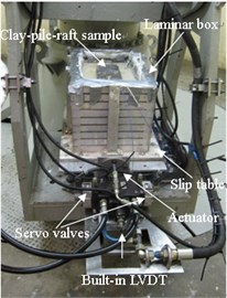
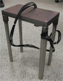
All the experiments were conducted at 50 g on the National University of Singapore (NUS) Geotechnical Centrifuge, which has a radius of 2 m and compromises a balanced arm with dual swing platforms. The centrifuge has a capacity of 40 g-ton and a maximum acceleration of 200 g. Earthquake waves can be input to model through a closed-loop electro-hydraulic servo-control shaking table that was fixed on the swing platform of centrifuge. The laminar box with inner dimension of 530 mm length by 300 mm width by 350 mm height was mounted onto the shaking platform, which is constructed from aluminum alloy and comprises nine rectangular laminar rings (Fig. 1(a)). More detail on the experiment set-up are available in Banerjee et al. (2007) [9], Ma K. (2014) [10].
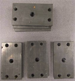
The soft soil used in this study was white kaolin powder which was mixed with water in a ratio of 1:1 and the slurry was poured in the rubber packed laminar box in layers. The pile-raft model comprises 4 cylindrical stainless-steel piles connected to a rigid steel raft which was partially embedded in clay bed during tests (Fig. 1(b)). Superstructure loads exerting on the raft were simulated using steel plates, which were added in stages onto the top of raft to simulate the effects of superstructure inertial forces (Fig. 1(c)). To measure the bending moment arising from kinematic soil-pile interaction, strain gauges labeled S1 to S5 were installed at five levels along the length of an instrumented model pile. Before centrifuge tests, strain gauges should be calibrated via cantilever method from at least 3 different loading cases as shown on Fig. 2. After two weeks of 1 g consolidation the laminar box was mounted on the Centrifuge along with all the equipments for generating earthquakes.
Fig. 1a) Setting up centrifuge-shaker platform, b) pile-raft model, c) steel plates for added masses
a)
b)
c)
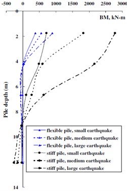
Fig. 3 shows typical envelops of bending moment for flexible and stiff piles from centrifuge tests. The maximum bending moment are both developed near the pile head, and its value increases with the earthquake intensity. There is a point at which the moment changes from positive to negative. This changeover point is much deeper for the stiff piles than for the flexible piles. For the flexible piles, the moment drops to a very small value below the changeover point. This is similar to the bending moment distribution curves for laterally loaded piles, and suggests that, for flexible piles, the clay beneath a certain depth is able to provide lateral support for the pile. The type of bending moment response is similar to that reported by Gazetas (1998) [11] and Nikolaou (2001) [12], who noted that an active pile length exists for head-loaded flexible piles. Below this depth, the pile would experience bending moments no more than 5 % of maximum value near the top. This seems to suggest that the flexible pile behavior during earthquake loading is similar in trend to that under head-loaded condition.
Fig. 2Strain gauges and calibration of the model pile
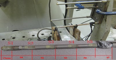
Fig. 3Bending moment envelopes for flexible and stiff piles
2.2. Numerical simulation using ABAQUS
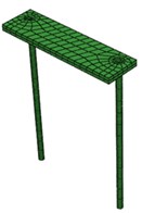
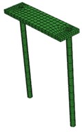
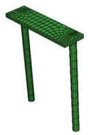
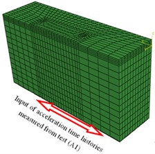
The numerical analysis was conducted using ABAQUS 6.11. Considering the symmetry of the tested model, a half 3-D model of pile-raft-clay system was built up as shown in Fig. 4, wherein the model was discredited into a total of 7742 20-noded brick elements and 64 3-noded beam elements . All the details about ABAQUS simulation skills can be seen in Ma K., et al. (2012) [13].
Fig. 43D ABAQUS model of Pile-raft system
a)0.5 m (26.0)
b)0.7 m
c)0.9 m
d) Pile-raft-clay system
Besides centrifuge tested piles which coverage to relative stiff and flexible piles, additional group piles (0.7 m) whose stiffness between the two (i.e. stiff and flexible piles studied in centrifuge tests) were complementary simulated by ABAQUS to get relatively adequate raw data of maximum bending moment required in next formula deduction. Table 1 summarized all the acquired maximum bending moments from centrifuge tests and ABAQUS simulation.
Table 1Piles used for the study (unit in prototype)
Results from | Pile group | Pile material | / KN/m2 | Diameter / m | Equivalent / GPa | Slender ratio |
Centrifuge and ABAQUS | Flexible pile | solid | 644271 | 0.5 | 210 | 26.0 |
concrete | 424360 | 138 | ||||
hollow | 380377 | 124 | ||||
Stiff pile | solid | 6763303 | 0.9 | 210 | 14.4 | |
concrete | 3244722 | 101 | ||||
hollow | 2541006 | 79 | ||||
Complementary ABAQUS analysis | Medium stiff pile | solid | 2473780 | 0.7 | 210 | 18.6 |
concrete | 1329250 | 113 | ||||
hollow | 1138495 | 97 |
3. Dimensionless analysis of maximum bending moment
3.1. Buckingham’s π theorem
Buckingham’s π theorem states that when a complete relationship between dimensional physical quantities is expressed in dimensionless form, the number of independent quantities that appear in it can be reduced from the original to , where is the maximum number of the fundamental dimensions. If the physical problem admits three fundamental dimensions such as length [], mass [], and time [], then will be equal to three [14].
Considering the single pile-raft system embedded in a uniform clay layer underlain by bedrock. The clay thickness is equal to the pile length, and the pile tip is resting on the bedrock. The system is subjected to rigid bedrock earthquake excitation. This is a complex soil-pile-raft interaction problem in which there are many factors at work, according to π theorem, all factors considered in this study should have some correlation between each other as expressed by Eq. (1):
This formula includes 9 dimension variables, as follows:
1) Maximum bending moment ,
2) Pile length ,
3) Pile diameter ,
4) Young’s modulus of pile ,
5) Mass of raft ,
6) Shear modulus of soil ,
7) Bedrock acceleration ,
8) Density of pile ,
9) Density of soil .
3.2. Dimensionless groups
As can be seen, there are altogether 9 quantities, herein selecting , and as 3 basic dimensions since they include 3 fundamental dimensions of length [], mass [], and time []. Hence 9 – 3 = 6 dimensionless groups need to be considered. These 6 dimensionless groups may be obtained as:
1) Dimensionless bending moment:
This expression is motivated by the relation between maximum strain, and corresponding bending moment, acting on a pile cross section of diameter, and Young’s modulus, :
2) Pile slenderness ratio:
3) Mass ratio of pile to raft:
Here can be expressed using active pile mass:
here assuming:
then:
4) Fundamental frequency ratio of pile-raft system to clay bed:
The most important factor in determining the response is the fundamental frequency ratio between a foundation and the adjacent ground in the free field. The ratio of unity indicates resonance condition between foundation and its adjacent ground, which is to be avoided. Pile-raft system can be considered as a SDOF system. In item Eq. (2), pile mass has been considered, so herein mass of pile is negligible compared to raft and is flexural rigidity of the pile.
Now, stiffness of the system can be worked out from simple structural analysis as:
where, is a constant whose value depends on the end condition. Hence natural frequency of the pile-raft system without soil:
Now, for a soil layer of thickness equal to length of pile (), fundamental period can be expressed as , where is the shear wave velocity in soil, .
Now, natural frequency of the soil:
Therefore, from equation Eq. (5c) and Eq. (5d), ratio of fundamental frequency of pile-raft system to that of clay:
5) Mass ratio of the equivalent ground domain affected by existing pile foundation to raft:
6) Dimensionless acceleration:
where is the gravitational free-fall acceleration.
3.3. Formulation of the dimensionless bending moment relationship
Following the usual convention in dimensional analysis, the effects of the various dimensionless groups are assumed to be multiplicative (eg: Nikolaou et al. 2001 [12]; Langhaar 1951 [15]), that is, the dimensionless moment is assumed to be related to the other 5 dimensionless groups () via a relationship of the form:
where . For soft cohesive clay under undrained condition, 0.5, .
Then:
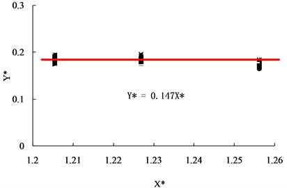
Though a trial and error process, the scattered distributed centrifuge results (14.4 and 26.0) and complementary ABAQUS results (18.6) (Fig. 5) can be condensed into a minimal narrow band as shown on Fig. 7 via a series of multiplying dimensionless groups step by step (eg. first step shown on Fig. 6), the best combination of coefficients, , , , , , and can be determined as shown on Eq. (10):
Fig. 5Original centrifuge and ABAQUS results
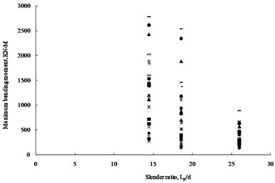
Fig. 6Relations between dimensionless moment M* vs Slenderness Ratio (lp/d)
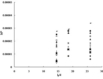
Fig. 7Final condensed plot after a series of linearization Y*= 0.147X*

Considering raft was sustained by 4 identical piles in this study, so 4, is the load sustained by each pile.
Then Eq. (10) changed to a general form:
Eq. (11) represents a correlated summary of the effects of various parameters on the maximum bending moment included in a single pile under earthquake loadings. This equation did consider the effect of loading applied onto the pile from superstructure, which is very important and cannot be neglected in practical design. This solution is only for fixed pile-head condition and embedded in a homogenous clay bed.
3.4. Comparison of Eq. (11) with design charts by Tabesh and Poulos (2007)
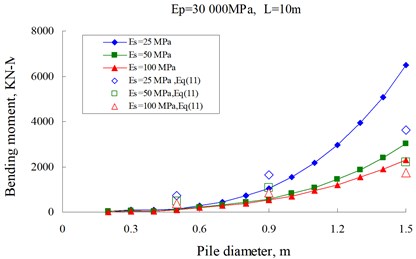
Tabesh and Poulos (2007) published design charts of maximum bending moment in single piles embedded in a linearly elastic homogeneous clay bed with a constant Young’s modulus of 25, 50 or 100 MPa and subjected to seismic excitation with a peak bedrock acceleration of 0.1 g, based on dynamic analysis of a Winkler soil-beam system [16]. The pile diameters ranged from 0.2 to 1.5 m, in 0.1 m increment. The pile modulus values used for the study were 10,000 and 30,000 MPa. In this analysis, the axial loads acting on the pile were evaluated as the ultimate load capacities of the pile, with factors of safety of 2, 2.5 and 3.
Corresponding to the same condition, Fig. 8 compares the results from Eq. (11) with the design charts for the case of 2. Generally, results from Eq. (11) based on the centrifuge results agree well with the trend of the design charts by Tabesh and Poulos (2007), although there still exists some discrepancies. This may be due to the fact that design charts gave by Tebesh and Poulos based some assumptions that the soil is an ideal elastic, isotropic material as well as purely elastic pile-soil interaction and purely elastic pile behavior are included in the analyses. This point may be more or less in disagreement with the real testing cases.
Fig. 8Comparison of bending moments from Eq. (11) with the design charts by Tabesh and Poulos (2007)
4. Conclusions
The purpose of this study was to understand the seismic behavior of the single-pile foundation in a uniform soft clay under different loading levels transmitted from superstructure during earthquakes. This study covered a comprehensive piles with slenderness ratios form 14.4 to 26.0 by both centrifuge tests and ABAQUS analysis, the conclusions can be listed as follows:
1) For the fixed-head piles, kinematic pile bending moments are largest near pile-raft connection, and its peak value increases with raft masses, flexural rigidity and earthquake intensity if keeping all the other conditions the same.
2) The pile response in bending moment for flexible pile is quite different from that of stiff pile. For flexible pile, there exists a active length below which no significant bending was observed, while for stiff pile, the relatively sigificantly restraining effect from surrounding clay on the lower section of pile produces a relatively maximum negative moment.
3) The maximum moment at the head of a capped pile depends on a number of soil and pile-raft parameters. Using the Eq. (11) obtained from the dimensional analysis, the engineer could obtain a first quick estimate of the maximum moment of a pile during an earthquake, after he (or she) has determined the peak ground acceleration and designed superstructure properties.
References
-
Ross G. A., Seed H. B., Migliaccio R. Bridge foundations in the Alaska earthquake. Journal of the Soil Mechanics and Foundations Division, Vol. 95, 1969, p. 1007-1036.
-
Tokimatsu K., Mizuno H., Kakurai M. Building damage associated with geotechnical problems. Soils and Foundations Special Issue on Geotechnical Aspects of the January 17, 1995 Hyogoken Nambu Earthquake, Vol. 36, Issue 1, p. 219-234.
-
Tajimi H. Dynamic analysis of structure embedded in elastic stratum. Proc. 4th World Conference Earthquake Engineering, Santiago, p. 53-69.
-
Penzien J. Soil-Pile Foundation Interaction. In Earthquake engineering. Chapter 14, New York, Prentice Hall.
-
Kavvadas M., Gazetas G. Kinematic seismic response and bending of free-head piles in layered soil. Géotechnique, Vol. 43, Issue 2, p. 207-222.
-
Nikolaou A. S., Mylonakis G., Gazetas G. Kinematic bending moments in seismically stressed piles. Report NCEER-95-0022, National Center for Earthquake Engineering Research, Buffalo, State University of New York, 1995.
-
Luo X., Murono Y. Seismic analysis of pile foundations damaged in the January 17, 1995 South Hyogo earthquake by using the seismic deformation method. Proc. 4th International Conference Recent Advances in Geotechnical Earthquake Engineering and Soil Dynamics, San Diego.
-
European Commission for Standardisation. ECN prEN 1998-5: 2003, Eurocode 8: Design of Structures for Earthquake Resistance. Part 5: Foundations, Retaining Structures and Geotechnical Aspects, 2003.
-
Banerjee S., Goh S. H., Lee F. H. Response of soft clay strata and clay-pile-raft systems to seismic shaking. Journal of Earthquake and Tsunami, Vol. 1, Issue 3, 2007, p. 233-255.
-
Ma K., Xu Q. Seismic softening behavior of pile-raft foundation constructed in clayey soil site subjected to far field earthquake. Journal of Vibroengineering, Vol. 16, Issue 2, 2014, p. 626-642.
-
Gazetas G., Mylonakis G. Seismic soil structure interaction: new evidence and emerging issues. Geotechnical Earthquake Engineering and Soil Dynamics, Vol. 2, 1998, p. 1119-1174.
-
Nikolaou S., Mylonakis G., Gazetas G., Tazoh T. Kinematic pile bending during earthquakes: analysis and field measurements. Geotechnique, Vol. 51, Issue 5, p. 425-440.
-
Ma K., Banerjee S., Lee F. H., Xie H. P. Dynamic soil-pile-raft interaction in normally consolidated soft clay during earthquakes. Journal of Earthquake and Tsunami, Vol. 6, Issue 3, 2012, p. 1250031.
-
Andrew C. P. Dimensional Analysis and Intelligent Experimentation. Singapore, World Scientific Publishing.
-
Langhaar H. L. Dimensional Analysis and theory of Models. John Wiley, New York.
-
Tabesh A., Poulos H. G. Design charts for seismic analysis of single piles in clay. Proceedings of the Institution of Civil Engineers Geotechnical Engineering, Issue GE2, 2007, p. 85-96.
About this article

This study was financially supported by Natural Science Foundation of China (51209180), China Postdoctoral Science Foundation (2012M511137), and Opening Foundation of State Key Laboratory of Chengdu University of Technology in China (SKLGP2012K014).
