Abstract
Dynamic behaviors of wind turbine drive train are concerned by engineers since they affect the whole working performances and the service life of wind turbine. In view of the asynchrony issue between excitation and response, we establish a coupled dynamic model and a dynamic error model for drive train with flexible sun-gear shaft. Then, the analysis and simulations of dynamic error are given. Furthermore, dynamic effects of flexible sun shaft on the drive train system are discussed. Our results show that the dynamic error is not only related to the inherent parameter of system but also the external load imposed on the system. In addition, the module value of dynamic error is constituted with synchronization error component and harmonic vibration component, and it cannot be ignored since they play a critical role on the natural frequency and exciting force. The results are also verified by the equivalent system.
1. Introduction
Most mechanical systems including shaft system are sensitive to operating environment such as manufacturing errors, excessive torque or installation problems. Due to the large gear ratio, the combination form of planetary and parallel gear sets is often applied in wind turbine drive train. Sun-gear shaft is a critical set which transmits the torque between planetary gear stage and parallel stage in wind turbine gearbox. When the running speed of the mechanical accelerates, dynamic error of drive train system may occur since the flexibility of the sun-gear shaft cannot be ignored. The transmission error of system is affected by a variety of factors. That is why there has been numerous researches works focusing on the planetary gear transmission system in recent decades. In these factors, the inherited parameters of the system were highly investigated owning to their determinative roles in the errors. So, research topics on the analysis of mesh stiffness [1], natural modes [2], and transmission errors [3] were mostly concentrated in the previously published documentations.
Most of the papers expanded the study on static error and the structural dynamics. However, fewer published literatures are available for dynamic error caused by the axis elastic deformation from the view of institutional dynamics point. The nonlinear dynamic model of translation-torsion coupling of gearbox system was investigated by Lin [4], the transmission errors of drive train system caused by instability parameters were discussed. Similarly, the robot system is also more sensitive to transmission error, a method for measuring the dynamic error of the flexible member of a robot was carried out by Qian Ruiming [5]. Since the stability and accuracy issues of transmission system required further study, kinetic model was considered more factors such as mesh stiffness, spacing and backlash-related nonlinear dynamics in recent years. An interactive method has been established for analyzing dynamic loads in a lightweight basic planetary gear system by August [6]. The effects of fixed, semi-floating and fully floating sun gear conditions had been emphasized by taking the gear mesh and manufacturing errors into consideration [7]. And it was further refined by Zhang Qingwei [8] that taking the load fluctuation into account, while a few dynamic error model caused by the axis elastic deformation is analysed from the view of institutional dynamics. The dynamic problems of wind turbine gearboxes have been studied recently. Guo et al. [9] studied the nonlinear effects introduced by bearing clearance. Velex et al. [10] researched the effect of planet position error on dynamic behaviors of planetary system. Furthermore Xing et al. [11] analyzed the effect of a spar-type floating wind turbine nacelle motion on drive train dynamics.
Motivated by above works, the present investigation is conducted to develop a recursive dynamics model on dynamic error of 1.5 MW wind turbine gearbox, which consider the shafting elastic deformation based on the Lagrange equation. The dynamic error of elastic member is introduced, and the effects of flexible shaft on drive train system are discussed. This is expected to supply the theoretical information for the stable operation of the system.
2. Basic structure of flexible shaft and floating support
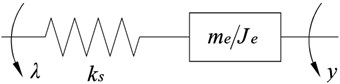
Fig. 1 shows the diagram of a 1.5 MW flexible shaft wind turbine drive train system, in which the drive train has a gearbox with three stages including a low-speed planetary gear stage and two high-speed parallel gear stage. The two stages showed in Fig. 2 are connected by sun-gear shaft which has a special structure with pipes and hollow shaft. The symbols shown in Fig. 1 are defined as below: is the input torque of gearbox, while represents the out torque, represents the planetary carrier, is the internal gear ring, represents the sun gear, 4 and 4′ are inter-mediate stage gears while 5 and 5′ are high-speed stage (output stage) gears.
In Fig. 1, the obvious feature of sun-gear shaft is elasticity and it plays an important role in outputting the torque and displacement from the planetary gear stage to parallel gear stage. It connected to the sun-gear of planetary gear stage in the left and supported by the spline bushing in the right. Because of the large length of suspension shaft, the stiffness of sun-gear shaft is lower than others. So it is difficult to keep balance under external load.
The sun-gear shaft can be assumed as a stepped shaft, and its stiffness can be easily derived according to the series of the each segment (1, 2,…, ) and expressed systematically with the formulation as follows:
Fig. 1Schematic diagram of drive train system
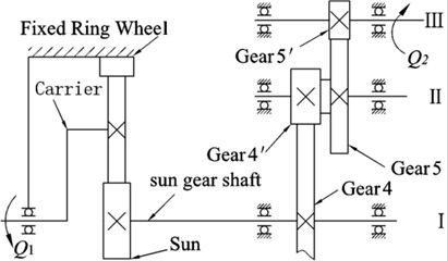
Fig. 2Structure diagram of sun-gear shaft
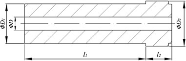
Where, is the inner diameter of the sun-gear shaft, while outer diameters are expressed by and , and represent the length of shaft. So the stiffness can be expressed as Eq. (2):
where is the shear modulus of shaft.
By taking a 1.5 MW wind turbine as the research object, the relevant parameters of the drive system are selected according to design parameters. They are listed in Table 1.
Table 1Gear parameter
Gears | 2 | 2′ | 3 | 4 | 4′ | 5 | 5′ |
Module / m | 12 | 12 | 12 | 10 | 10 | 6 | 6 |
Tooth number / z | 43 | 111 | 23 | 99 | 23 | 104 | 27 |
3. Dynamical model of drive train system
Based on the above assumptions, the dynamic model of drive train system shown in Fig. 3 is developed by using Lagrange’s equations method to obtain the equations of the torsional vibrations [12]. Making a conversion of the load and the moment of parallel shaft to the sun-gear shaft, so that the tandem gear transmission system can be equivalent to a single-axis system as shown in Fig. 3.
Fig. 3The dynamic model of drive train with flexible shaft
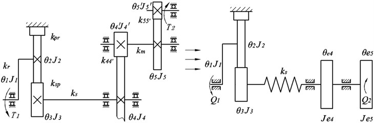
All gears are defined as spur gears, whose movements are determined through a rotation degree of freedom (DOF), ( 1, 2, 3, , ) represent the absolute rotational displacement of component respectively. is stiffness of component , ( 1, 2, 3, , ) are the moment of inertia of component , respectively and there are three planets drove by plant carrier. The vector of the generalized co-ordinates is:
The differential equations describing the torsional vibrations of drive train are:
The matrices and describe the linear properties of mass inertia and stiffness, their numbers are:
The vector of the external forces caused by the wind and generator is:
where and are the aerodynamic torque and generator torque. The generator torque of generator is obtained by Eq. (8):
where is the rated power of generator, is the design speed. For rated power of wind turbine, aerodynamic moment of the rotor can be calculated by the following form:
where that is the product of blade chord with the thickness of span wise, represents the air density, is the speed of the air flow, and represents the inclination of blade element.
4. Model and analysis of dynamic error
4.1. Modelling hypothesis
In order to consider the effect of torsional deformation of sun gear shaft on the output motion of high-speed shaft ignoring the effect on the system of any other factors, they are in the list of assumptions made here for the sake of completeness. The gear mesh model is a linear time-invariant model. Variable stiffness of tooth pairs in contact is assumed negligible and therefore the transmission ratio is constant. Drive shaft is deemed to be torsion spring and the quality of the shaft does not take into account; the flexibility of support in structure is neglected as well as any other possible damping in the system.
4.2. Establishment of error equation
The parallel stage in wind turbine gearbox is a common tandem gear transmission. For easy to analyze the dynamic error caused by the torsional deformation of sun-gear shaft, we make the conversion of the load and the moment of parallel shaft to the sun-gear shaft based on the above assumptions and the conservation laws of energy. For the reason that the tandem gear transmission system can be equivalent to a single-axis system as the form shown in Fig. 3, the angular displacement of each shaft can be obtained. Each gear engaged with a fixed speed ratio in the case of excluding teeth elastically deformable, an analysis is conducted about the law of motion of the mechanism only from the point of institutions geometric position. The parameters and are defined as the vector of the generalized co-ordinates, the displacement of the sun is:
where and are teeth number of the gear and . Based on above relationship, the following calculation can further simplify the model.
Calculated transmission ratio for each axis according to the number of teeth in meshing gear:
Coordinate transformation:
Equivalent moment of inertia:
The generalized force:
According to equivalent conversion, equivalent dynamic model of the transmission system is simplified as the form of Fig. 3, and therefore the two series gear transmission system which composed of triaxial system simplifies uniaxial system. Based on the equivalent dynamic model, the dynamic error equations are established. In this article the dynamic-static force principle is used to obtain the dynamic equations of drive train system. It takes the following form:
That is the external force (torque) of the rigid body and the inertial force (torque) is in the equilibrium state. The dynamic equations of each module in the system are:
Assuming is the input displacement of gearbox system, and is the output, according to the transmission ratio of the gearbox, synchronism output of gearbox should be ·. However, it is inconsistent of mechanism between actual output and theory output because of elastic deformation of the sun-gear shaft. Therefore the transmission error is generated. The dynamic error of the system is defined as the difference between the output and the actual input , so the dynamic error of the gearbox can be expressed as:
It should keep the synchronous relationship between output and input under rigid condition, this implies that the error is zero, when the elastic deformation of sun-gear shaft is taken into account, the conversion of the dynamic error equation to a generalized coordinate system is:
The mathematical model of the gearbox system of wind turbine has established involves two degree of freedom (DOF), the numerical method are often implicated to solve the numerical solution in engineering, thus the response of the internal structure of the system can be analyzed. Since the differential Eqs. (16) and (17) coupled by two DOFs, by means of the four-order Runge-Kutta’s method, the numerical solution of and are calculated, then the result are introduced into the error Eq. (19), the dynamic error is obtained as shown in Fig. 4.
By this token, the amplitude value of dynamic error which is caused by the elastic deformation of the sun-gear shaft simply became larger and larger with the passage of time, and the effect was more significant as the angular displacement of rotor increased. In general, the curve shows a form of free vibration and its amplitude increases gradually over time.
Fig. 4Dynamic error curve of system
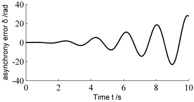
Fig. 5Model of equivalent system
4.3. Error analysis
Dynamic response of the elastic member is often associated with the operation speed of mechanism, especially it will produce unpredictable vibration response and affect the performance of the transmission system if the error becomes systemic incentive. In order to find out the basic reasons for causing the error, a simplification of system is made according to the law of conservation of energy, the sun and the former part are regard as driving member of system, and the latter are driven member, at the same time, an equivalent transfer of mass and moment of inertia of various components is made to sun-gear shaft (Fig. 5) [13].
The differential equation describing the torsional vibrations of the equivalent system is:
where is the equivalent moment of inertia of system, is the input of system, is the angular displacement of sun, is the law of output motion of high-speed shaft.
By regarding as the known quantity, the analytical solutions of Eq. (20) are derived and then used to analyze the relationship between system parameters and the dynamic error of system. The solution for is:
It will be convenient for analyzing the effect on the input and output of gearbox caused by elastic deformation of sun-gear shaft, a coordinate transformation is carried out from original coordinate system to , that is . Therefore, the Eq. (21) can be changed into Eq. (22):
Then the dynamic error model can be expressed as:
It can be seen, the dynamic error can be resolved into two linear superposition components: one of components can be named as synchronization error which is synchronized with the input and it can be expressed by the expression the change of the synchronization error have a form of linear distribution is shown in Fig. 6 (). The value of this part is affected by the drive ratio and , the formulae is the instantaneous rate of change. However, in some cases, the value of dynamic error can be minimized by optimizing the instantaneous rate of change. That is the elastic deformation of sun-gear shaft can be ignored when the stiffness of sun-gear shaft reaches to infinity, therefore, this component of dynamic error is synchronized with the input, and . In other words, the synchronization error can be compensated through increasing the rigidity of shaft or optimizing the transmission form of sun-gear shaft.
Fig. 6Simulation of dynamic error
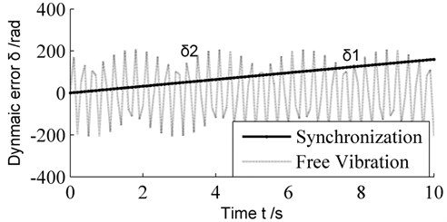
Another component of dynamic error can be expressed as the form named free vibration error, the production of is the result of free vibration of system, which is a simple harmonic motion whose frequency is the natural frequency superimpose on the motion of original design shown in Fig. 6 where . Owing to is the moment of inertia of various components, so is the result of vibration system included sun-gear shaft and the transmission parts of parallel shaft. Although its vibration form is manifested as free vibration caused by impact load, the vibration amplitude can be reduced due to the existence of damp. However, the vibration problem is difficult to solve because of the periodic motion of shaft and the random excitations. More importantly, the gear meshing impact may be induced by this vibration and it will affect the performance of the gearbox. Therefore, the kinetic parameters of system such as the moment of inertia and the structural stiffness should be designed more reasonable. Furthermore, we can obtain the system’s optimization design.
5. Dynamic effects of the flexible shaft
5.1. Effect on the dynamical torque of sun-gear shaft
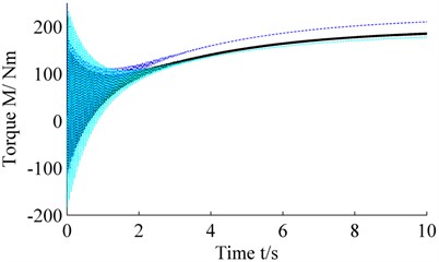
All the excitation force and displacement are transmitted by the sun-gear shaft from planetary gear stage to parallel gear stage, thus studying the force of sun-gear shaft allows us to keep the stability of the power output. Dynamical torque of sun-gear shaft reads:
The simulation time varies from 0 s to 10 s to show the dynamical torque with the stiffness of sun-gear shaft. Fig. 7 shows the dynamical torque of sun-gear shaft with the stiffness of flexible shaft being and respectively, curve 1 represents the response of , curve 2 represents the response of and curve 3 represents the response of . It can be seen that, with the increase of the stiffness of sun-gear shaft, the dynamic torque of sun-gear shaft is also on the increase, but in the initial time, the amplitude of dynamical torque decrease, this is conducive to maintain the stability of starting process. Therefore, we find that increasing the stiffness of flexible sun-gear shaft properly can increase the dynamical torque and will alleviate the vibration conditions at the initial time. So the impact of the shaft flexibilities on the torque dynamics cannot be neglected.
Fig. 7Effect on the dynamical torque of sun-gear shaft
5.2. Effect on natural frequency
The natural frequencies and model shapes are obtained by Eq. (4):
where is the eigenvector, is the corresponding eigenfrequency. So we can get the relationship between the natural frequencies and the stiffness , the results are accomplished using the codes of MATLAB showed in the Fig. 8.
From Fig.8 we can know that because of the drive train was divided into two subsystems: the planetary gear stage and the parallel gear stage, the model of the whole drive train system was coupled with the two parts, so we calculated three types of modes for the system, the curve 1 represents the frequencies of planetary gear stage, while the curve 2 represents the frequencies of parallel gear stage, and curve 3 is the frequencies of coupled frequencies of the two gear stages. The range of the stiffness of flexible shaft is set from 105 to 1011 N/m in order to obtain the effect of stiffness on natural frequency. It can be seen that the coupled frequency is more than the planetary or parallel gear stage, the planetary gear stage frequency changes obviously as the stiffness of flexible shaft decrease, and the coupled frequency is same with planetary gear stage frequency. However, the parallel gear stage frequency does not change remarkably, the planetary gear stage frequency plays a decisive role over the full frequency range since the low natural frequency would increase.
Fig. 8The relationship between frequencies and stiffness ks
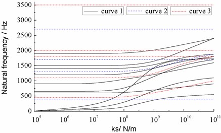
It can be seen that the synchronization error can be compensated through increasing the rigidity of shaft, on the other hand, the low frequency will increase as the stiffness increase, it is beneficial to avoid resonance during starting process, so it is an effective way to decrease the low frequency of drive train system.
5.3. Effect on dynamic response
The rated torque of sun-gear shaft is 179.4 Nm, and the corresponding stiffness is Nm/ rad. Taking the rated torque as the parameter of sun-gear shaft, the dynamic simulation of drive train system is conducted. The input torque on the main shaft is taken as rotor torque, and the output torque on generator is electromagnetic torque. Fig. 9 shows the acceleration response of sun-gear shaft in time domain and frequency domain. In can be seen that the acceleration peek occurs at 4.53 s, and the main acceleration fluctuates between –10-10 rad/s2, and the main frequency around 8.2 Hz, 630 Hz and 1320 Hz which correspond to the planetary gear stage frequency, in another word, the acceleration of sun-gear shaft is more than other frequencies, so it is easily lead to resonance between planetary gear stage and the sun-gear shaft.
Fig. 9The acceleration of sun-gear shaft
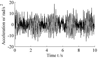
a) Acceleration in time domain
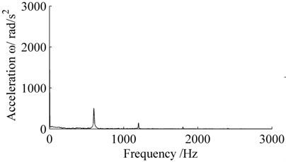
b) Acceleration in frequency domain
6. Conclusions
The structure of flexible shaft has been widely adopted in wind turbine. This work presents a coupled dynamic model and a dynamic error model of a wind turbine drive train system with flexible shaft based upon the Lagrange’s equations method. The drive train system is divided into planetary gear stage and parallel gear stage to study dynamic error and dynamic behaviors of drive train system with flexible shaft. Effects of stiffnesses of flexible shaft on dynamical torque, natural frequencies, dynamic responses are discussed. Conclusions are made as below: The dynamic error is consists of synchronization error and free vibration error, the former is synchronized with the input of system, and the latter caused by the impact load. On the other hand, the types of the dynamic error are determined by the structural parameters, and the external excitations determine the amplitude of error and how long it will work. Increasing the stiffness of flexible sun-gear shaft properly can increase the dynamical torque and will alleviate the vibration conditions at the initial time. The synchronization error can be compensated through increasing the rigidity of shaft, on the other hand, the low frequency will decrease as the stiffness decrease, it is beneficial to avoid resonance during starting process; the acceleration peek of sun-gear shaft occurs at the same time of its main frequency. It is easily lead to resonance between planetary gear stage and the sun-gear shaft, so we should avoid it.
References
-
Velex P., Flamand L. Dynamic response of planetary trains to mesh parametric excitations. Journal of Mechanical Design, Vol. 118, 1996, p. 7-14.
-
KahramanA. Natural modes of planetary gear trains. Journal of Sound and Vibration, Vol. 173, Issue 1, 1994, p. 125-130.
-
Chaari F., Fakhfakh T. Influence of manufacturing errors on the dynamical behavior of planetary gear. Internal Journal of advance manufacture technology, Vol. 27, Issue 7, 2006, p. 738-746.
-
Lin J. Analytical investigation of planetary gear dynamics. The Ohio State University, Columbus, 2000.
-
Qian R. M. Integrated laser-optical measurement and compensation of dynamic errors for flexible manipulators. Mechanical Science and Technology, Vol. 20, Issue 2, 2000, p. 251-252.
-
August R. K. Torsional vibrations and dynamic loads in a basic planetary gear system. Journal of Vibration and Acoustics, Vol. 108, Issue 3, 1986, p. 348-353.
-
Zhu C. C., Huang Z. H., Tang Q. Analysis of nonlinear coupling dynamic characteristics of gearbox system about wind-driven generator. Chinese Journal of Mechanical Engineering, Vol. 41, Issue 8, 2005, p. 203-207.
-
Zhang Q. W., Zhang B., Wang J. H. Dynamic optimization design of gear transmission system for wind turbine. Journal of Chongqing University, Vol. 33, Issue 3, 2010, p. 30-35.
-
Guo Y., Parker R. G. Dynamic modeling and analysis of a spur planetary gear involving tooth wedging and bearing clearance nonlinearity. European Journal of Mechanics – A/Solids, Vol. 29, 2010, p. 1022-1033.
-
Gu X., Velex P. A dynamic model to study the influence of planet position errors in planetary gears. Journal of Sound and Vibration, Vol. 331, Issue 20, 2012, p. 54-74.
-
Xing Y., Karimirad M., Moan T. Effect of spar-type floating wind turbine nacelle motion on drive train dynamics. Copenhagen, Denmark: European Wind Energy Association (EWEA) Annual Event, 2012.
-
Liu W. Y. The vibration analysis of wind turbine blade–cabin–tower coupling system. Engineering Structures, Vol. 56, 2013, p. 954-957.
-
Kahraman A. Modeling and digital simulation research for wind power transmission system. Acta Energiae Solaris Sinica. Vol. 31, Issue 11, 2010, p. 1503-1509.
About this article

The research described in this paper was financially supported by the National Natural Science Foundation of China (51165019) and the National Natural Science Foundation of China (50875118).
