Abstract
The container vehicle-truss bridge coupled vibration greatly affects the automated container terminals’ (ACT) structural safety and handling efficiency. Using free-interface component mode synthesis (CMS) method, the coupled vibration time-domain responses, under self-excitation including track irregularity and hunting movement as well as environmental excitations such as wind and seismic load, were obtained. Stochastic simulation of track irregularity and fluctuating wind time-history was generated based on the numerical simulation method of multidimensional homogeneous process. A scale model test was introduced to validate the CMS method’s effectiveness and vehicle speed’s influence on coupled vibration response. In this case, the vehicle-bridge vertical vibration is caused mainly by the vehicle moving load, and self-excitation is a major factor. Wind, seismic load will greatly enhance the lateral vibration. And the sensitivity of the response to the seismic load is greater than operational wind load. As vehicle velocity, fluctuating wind mean velocity or ground motion intensity increase, the responses increase. Then, the structural safety, running safety and stability were assessed by the indicators such as deflection-span ratio, acceleration response etc., under wind load only and under operational wind and ground motion excited simultaneously. It is proved by both prototype simulation and model test results that, lead rubber bearing (LRB) can effectively reduce the acceleration response of both the vehicle and the bridge; therefore, can raise vehicle speed limits for structural and running safety.
1. Introduction
Vehicle and bridge coupled vibration (VBCV) analysis has been widely carried out in the area of rail transportation. VBCV is actually one kind of moving-load dynamic problems. Ouyang [1] gave a tutorial with a brief overview of a variety of moving-load problems discussed by recently published papers and books. Au et al. [2] reviewed vibration analysis on bridges under moving loads, in particular, trains. Moving-load dynamic problems also occur in the field of port machinery, especially, cranes. For example, a gantry crane and bridge crane travel along tracks; the trolley moves along the girder beams and carries a payload that can swing about and excite the whole structure into vibration [3, 4].
Many factors affect the vibration of vehicle-bridge system, including self-excitation (track irregularity and hunting movement) and external excitation (wind and seismic load), usually, these excitations are random variables. Chatterjee et al. [5] modeled the surface irregularity as a stationary random process characterized by a power spectral density (PSD) function and it was generated from Monte Carlo simulation. Dinh et al. [6] studied surface irregularity of the track. At present, multi-rigid body-spring-damper discrete model is adopted as the vehicle model while FEM model as bridge model. Then the system equation is formed though wheel-rail interaction. The equation is solved in the time domain due to time-varying [7-21].
Wheel-rail interaction is the key issue of VBCV. Generally speaking it is treated in the following ways: 1) both measured track irregularity and hunting movement are assumed to be the wheel-rail interaction [7, 8]. 2) Measured or artificial profile of bogie frame hunting movement is considered as the system input [9, 10]. Both the above two ways consider main characteristics of wheel-rail interaction on the basis of measured data. 3) Each wheel is simplified to be a tapered tread, which can be defined as the gravity stiffness and then the interaction force of each wheel-rail is acquired [11]. 4) The creep force and kinematical relation of the wheel-rail model can be calculated iteratively by rolling contact theory, such as Hertz theory [12, 13]. Among the four ways, only the last one is able to determine the contact point and contact force of wheel and rail precisely. However, this procedure is very complicated. If the aim is not the wheel-rail kinematical relation but the coupled vibration of vehicle-bridge system, the first three methods are reasonable effectively.
Two main external excitations of vehicle-bridge system are wind and seismic loads. Many researchers have studied VBCV, such as long-span cable stayed bridges or suspension bridges, under disturbing wind or seismic circumstances [8-19]. Both wind or earthquake effect on vertical and lateral vibration was presented and safe speed limit was gained. The free-interface component mode synthesis (CMS) is very popular because of high efficiency and convenient combination with the experimental modal technique [16, 20]. Interface compatibility conditions can be considered approximately as wheel-rail interaction. Vehicle and bridge is combined to one entire system for coupled vibration analysis [7, 14, 16].
This paper utilizes the dual-compatible free-interface Component Mode Synthesis (CMS) method and structural scale modal test to solve and validate the coupled vibration of a container vehicle-truss bridge system under the above mentioned excitations for an automated container terminal (ACT) scheme [20]. Then structural safety of the truss bridge and vehicle, running safety and stationarity of the vehicle are assessed.
2. Coupled vibration formulation of the vehicle-bridge system
2.1. The container vehicle – truss bridge distribution system
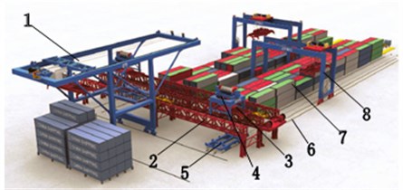
Container transportation between crane yard and storage yard is implemented usually by AGVs, which have many drawbacks, such as serious interference among AGVs. Virtual Reality simulation for ACT construction configuration illustrated in Fig. 1 presents one three-dimensional container distribution system between crane yard and storage yard. This structural system includes container crane, container vehicle-truss bridge system, ground railway, and ground rotary container vehicle, etc. Container distribution procedure is described as follows and vice versa: firstly, crane 1 lifts one container from one vessel to one container transport vehicle 3 seated on the truss bridge 2. Secondly, the transport vehicle 3 runs and reaches certain position in high speed and then lifted down to one ground rotary container vehicle 4 by one lifting vehicle 5. Thirdly, the ground vehicle 4 with one container drives to the storage yard 7 on the track 6.
Fig. 1Virtual reality simulation for automated container terminal (ACT) experimentation. 1. Container crane, 2. Truss bridge, 3. Container transport vehicle, 4. Container lifting vehicle, 5. Ground rotary container vehicle, 6. Ground track, 7. Yard, 8. Track crane
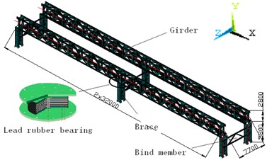
The braces and truss beams of the bridge are linked in all rigid (weld and bolt connection) or all flexible (LRB connected) way. Overall size of the truss bridge is shown in Fig. 2.
Fig. 2Structural schematic diagram of the truss bridge
Compared to existing ACTs, this scheme has many advantages: 1) Three-dimensional transportation replaces the ground planer way, which solves the AGVs’ interference problem. 2) No longer rely on GPS navigation and positioning system, but adopt a more convenient and more accurate orbital positioning. 3) The vehicle and truss bridge distribution system is less expensive than the AGV system. Last but not the least, green power drive of the entire system is utilized and thus operating cost is reduced.
However, in this scheme, the truss bridge suffers from moving load, container and vehicle self-weight. Wheel and rail interaction under self-excitations as track irregularity and hunting movement, external excitations including wind and seismic load, induces lateral and vertical coupled vibration which in turn affects the operating safety and stationarity of vehicle and bridge system. Studies on the coupled vibration of the vehicle and truss bridge system are the necessity for structure safety performance and handling efficiency.
2.2. Vehicle and bridge substructure model
Vehicle and bridge substructure FEM model were established. Among the model, the truss bridge and each vehicle are divided into free-interface subcomponents. Track model is not established and wheel DOF and rail DOF are considered as the interface freedoms of vehicle and truss bridge respectively.
According to Dual-compatible free-interface CMS method, using the first normal mode set and remaining attached to mode set as substructure’s assumed mode set.
By mass matrix normalization and application of Raleigh damping model, the vibration equation of each vehicle substructure in modal coordinate system is derived via the first coordinate transformation:
Neglecting the left superscript and blocking matrix:
where, are Raleigh damp constants; () are s order natural frequency and damping ratio of substructure.
Replacing left superscript in the Eq. (1)-(2) by the superscript the truss bridge substructure dynamic equation can be obtained. Meanwhile, LRB (lead rubber bearing) use equivalent linear model and mechanical parameters can be referred [20].
Assume that there is no relative displacement between rail and truss beam, considering self-excitation (track irregularity and lateral hunting movement), thus the bridge interface displacement:
where, , , are respectively the bridge interface displacement, wheel set hunting movement, and track irregularity.
2.3. Wheel set hunting movement description
Vehicle wheel set hunting movement can be expressed by [11]:
where, is hunting movement amplitude, random value between measured value and maximum clearance of wheel and rail, that is, ; is the vehicle velocity, m/s; is wheel set initial phase, uniformly distributed between 0 and , rad; is the wavelength of hunting movement, considering various factors such as wheel wear, it is uniformly distributed like . is free wheel set hunting movement wavelength. is the wavelength under the constraint of upper frame. Random variable can be generated by random function.
2.4. Coupled dynamic equation of vehicle-bridge system
Assume that: (1) wheel is a rigid body always contacting with rail, that is, the wheels do not jump; (2) small displacement vibration of both vehicle and truss bridge; (3) neglect effect from vehicle longitudinal movement on the bridge vibration and vehicle velocity. Interface compatible conditions are utilized to assembly vehicle-bridge coupled equation. Without loss of generality, consider one vehicle and truss bridge coupled vibration problem.
Two substructure equations can be given as follows:
According to interface force and interface displacement compatible conditions:
Achieve the second coordinate transformation:
with:
Until now, the coupled vibration equation of vehicle and bridge is derived as:
where, are achieved by one contra gradient transformation to mass, stiffness and damp matrix in Eq. (5). is the product of and right load vector in Eq. (5). All interface forces are cancelled out and external load vectors, such as wind and seismic load, are remained. Eq. (12) is a time-variant second order difference equation which can be solved by the Newmark- numerical integral method.
3. Numerical simulation of stochastic processes
3.1. Track irregularity
The most effective means to describe the characteristics of the track irregularity is the statistics analysis of power spectrum density (PSD) [5, 6]. Since there is no track irregularity of the measured data in the research field of port machinery, when the truss bridge in the introduced automated container terminal (ACT) experimentation was constructed, the track irregularity was referred to the design and construction standards of China's high-speed railway, such as TB10601-2009, TB10621-2009 etc. Generally, it is specified that the accepted track irregularity values of construction completion are within 4 mm. On the other side, the QU80 type crane rail is similar to the railroad track in terms of weight and geometry, and the container vehicle’s highest speed (20 m/s) is close to ordinary high-speed train. Therefore, we used the track irregularity of railroad to approximately describe the container vehicle-truss bridge’s rail irregularity. The track irregularity PSD in Eq. (13) is fitted from the collected data on Zheng-wu high-speed line test section by China Academy of Railway Sciences with specialized data detection and acquisition rail vehicle:
where, is the irregularity PSD, mm2/(1/m); is the irregularity spatial frequency, 1/m; , , , , , , are characteristic coefficients, taken from Table 1 [11]. In this paper, mainly left and right track lateral and vertical irregularity are considered.
Table 1Power spectral fitting curve parameters for China’s 60 kg/m track of seamless line [11]
Parameters | |||||||
Vertical irregularity of left track | 0.1270 | –2.1531 | 1.5503 | 4.9835 | 1.3891 | –0.0327 | 0.0018 |
Vertical irregularity of right track | 0.3326 | –1.3757 | 0.5497 | 2.4907 | 0.4057 | 0.0858 | –0.0014 |
Lateral irregularity of left track | 0.0627 | –1.1840 | 0.6773 | 2.1237 | –0.0847 | 0.034 | –0.0005 |
Lateral irregularity of right track | 0.1595 | –1.3853 | 0.6671 | 2.3331 | 0.2561 | 0.0928 | –0.0016 |
Considering of weak correlation between different directions, the Shinozuka’s method [21] was utilized to simulate one-variant multidimensional homogeneous process. Such left and right track lateral and vertical irregularity is illustrated in Fig. 3. From Fig. 3, all the resulting track irregularity curves have significant stochastic characteristics, fluctuating within ±4 mm specified in the standards. Moreover, PSD of simulated sample is observed to agree with the target (i.e. the fitting PSD from the measured data), one example is as shown in Fig. 4. These track irregularity data are then substituted into Eq. (3) for vehicle-bridge coupled vibration numerical simulation.
Fig. 3Vertical and lateral track irregularity curve of the left and right track
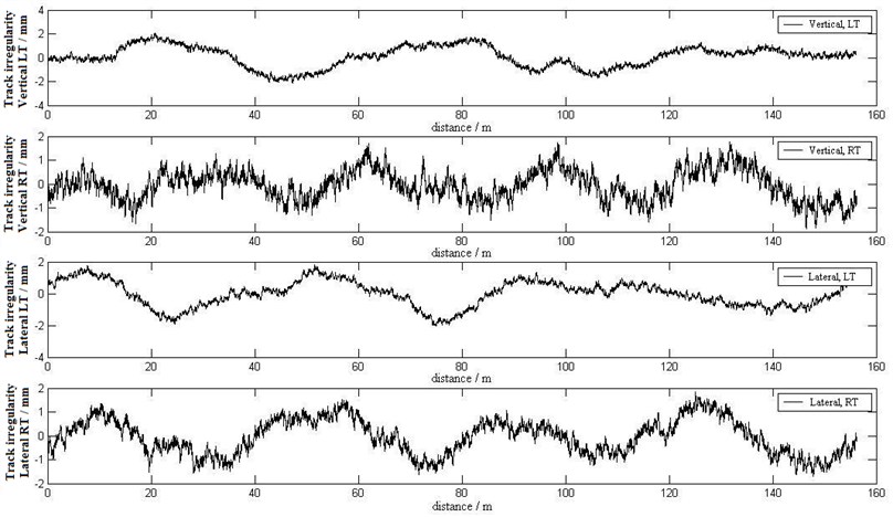
Fig. 4Comparison of the theoretical spectrum and the simulated spectrum of the left track’s vertical irregularity
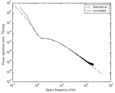
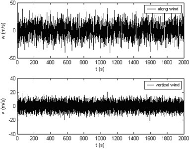
Fig. 5Time history of along-wind and vertical-wind fluctuating wind velocity (U-(10)=60 m/s)
3.2. Wind load
In engineering, three-dimensional correlation wind field is usually simplified to three uni-direction independent wind field [8-10]. For the truss bridge and vehicle structure, only need to consider uni-dimensional field in and direction:
where, denotes along-wind mean wind velocity; denotes vertical and lateral fluctuating wind respectively.
In this paper, Kaimal spectrum Eq. (15) and Lumley-Panofsky spectrum Eq. (16) are selected to simulate along-wind and vertical-wind:
where, Hertz frequency , and shear velocity , m/s:
with height , m; ground roughness , m; mean velocity at height.
By the Shinozuka’s method [21], if , along-wind and vertical-wind velocity time-history curves is illustrated in Fig. 5. Simulated PSDs also agree well with the targets. Thus, the wind load on the vehicle-bridge system can be obtained by the relationship between wind load and wind velocity.
4. Coupled vibration response results under self-excitation or environmental excitation
4.1. Self-excitation response and scale model test validation
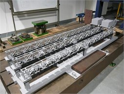
Take Force, Length and Time as fundamental dimension system ([F, L, T]), structural dynamic similarity principles can be derived via dimensional analysis. Similarity principles and similarity constants for main physical variables are listed in listed in Table 2. The designed model is shown in Fig. 7.
Table 2Similarity principles of dynamic structural model test
Physical variables | Dimension | Similarity principles | Similarity constants |
Length | [L] | 1/30 | |
Mass | [FL-1T2] | 1/302 | |
Stiffness | [FL-1] | 1/30 | |
Damp | [FL-1T] | 1/303/2 | |
Density | [FL-4T2] | 30 | |
Time (period) | [T] | ||
Velocity | [LT-1] | ||
Acceleration | [LT-2] | 1 |
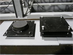
Fig. 7Photos a) of the truss bridge and b) the LRB models
a)
b)
Under all rigid or flexible support constraint, maximum acceleration response amplitude values of scale model test and prototype simulation by self-excitation are listed in Table 3.
Table 3 presents that the Max. response amplitude values of the model test and prototype simulation agree with each other very well, so do the time-history curves waveform of the response results. The vehicle-bridge response value increases with vehicle velocity. Moreover, under all flexible support, the responses are obviously less than that under all rigid supports, which indicates that the LBR can effectively reduce the acceleration response.
Table 3Maximum acceleration response comparison of model test and prototype simulation
Prototype vehicle speed (m/s) | Support form | Maximum acceleration response of bridge (m/s2) | Maximum acceleration response of vehicle (m/s2) | ||||||
Vertical | Lateral | Vertical | Lateral | ||||||
Test | Simulation | Test | Simulation | Test | Simulation | Test | Simulation | ||
4 | Rigid | 2.05 | 1.54 | 0.15 | 0.16 | 0.26 | 0.069 | 0.32 | 0.220 |
Flexible | 1.37 | 1.32 | 0.14 | 0.12 | 0.22 | 0.063 | 0.29 | 0.218 | |
6 | Rigid | 2.07 | 1.60 | 0.20 | 0.20 | 0.38 | 0.129 | 0.61 | 0.410 |
Flexible | 1.70 | 1.34 | 0.16 | 0.15 | 0.41 | 0.126 | 0.48 | 0.397 | |
8 | Rigid | 2.23 | 1.65 | 0.19 | 0.24 | 0.49 | 0.223 | 0.81 | 0.634 |
Flexible | 1.80 | 1.38 | 0.18 | 0.20 | 0.55 | 0.238 | 0.73 | 0.576 | |
4.2. Coupled vibration response under wind load
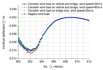
When one line is on operation, dynamic response is illustrated in Fig. 8 and Fig. 9. In order to reduce the influence of the transient response induced by wind load, before the vehicle-bridge coupled vibration simulation, 600 seconds’ truss bridge response under wind load only was calculated, as shown in Fig. 8(a), the first 600 seconds (0-599 s) is the stage under wind load only; and later (600-612 s) is the stage of the coupled vibration under wind load, as shown in Fig. 8(b). It can be seen from Fig. 8(a) that the transient response by wind load gradually decay under damping, which means the stochastic wind load will not cause the truss bridge resonance. So does the lateral transient response, thus Fig. 9 demonstrates only the coupled vibration response time-history.
Fig. 8Displacement response time-history curves of the node in the middle of the bridge (vV= 4 m/s)
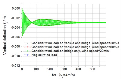
a) Under wind load only
b) Coupled vibration under wind load
It can be observed that the wind load affects the bridge vertical deflection little. The wind load affects mainly the lateral dynamic response of the bridge and vehicle. The vertical acceleration response of the vehicle is less than the lateral acceleration (also seen in Table 3). Both Fig. 8 and Fig. 9 indicate that self-excitation is the main factor of the entire vehicle-bridge system vibration. Here, wind load only amplifies the vibration amplitude, which differs from that wind load is the main factor to induce the lateral vibration of long-span high-speed railway bridge [7-9]. During analysis, the wind load on the container cannot be neglected in case large error will be produced. Therefore, wind load is applied on the entire vehicle-bridge system and influences the coupled vibration.
Fig. 9Lateral acceleration response time-history curves of the vehicle (vV= 4 m/s)

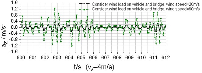
Meanwhile, the coupled vibration varies with mean wind velocity and the vehicle speed. Displacement and acceleration of the vehicle and bridge increase with the mean wind velocity, especially in the lateral direction.
Moreover, the coupled vibration is influenced by the vehicle operation condition, one line single-running or two lines double-running. When double-running, maximum lateral acceleration is obviously larger than single-running. This fact indicates that two lines correlate with each other, especially in the lateral direction.
4.3. Coupled vibration response under seismic and operational wind load
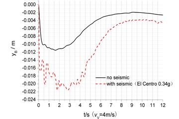
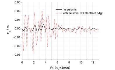
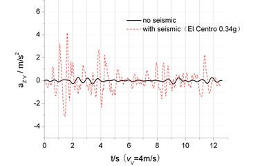
One typical seismic code, such as EI Centro wave was applied to the vehicle-bridge system and neglected multi-point excitation and traveling-wave effect. In simulation, mean wind velocity and lateral seismic acceleration were taken 20 m/s and 0.34 g respectively, because that Typhoon (or storms, hurricanes) and earthquake this two kinds of extreme external environment excitation occur at the same time is very unlikely. The starting point is properly selected to assure the occurrence of maximum acceleration. On all rigid supports, when the vehicle is running at 4 m/s in two line way, the vertical and lateral displacement and acceleration in the middle of the bridge with and without seismic load is compared in Fig. 10.
Fig. 10 shows that when seismic load applied, the maximum response and frequency value become larger than that without earthquake load. For example, the displacement and acceleration in middle span under seismic load is 1.9, 4.6 and 12.4 times than that without. Furthermore, vertical displacement time-history in middle span presents moving vehicle load is significant for the coupled vibration and that seismic load mainly affects the amplitude. However, in lateral vibration analysis, all time-history curve is similar to EI Centro wave, which means that seismic load is main cause, compared to operational wind load and self-excitation. Therefore, if the construction site probably suffers from rarely occurred earthquake, seismic load must be considered in the design.
Fig. 10The dynamic response comparison of the vehicle-bridge vibration under either seismic load or not
a) Vertical displacement
b) Lateral displacement
c) Lateral acceleration
5. Structural safety assessment for the vehicle-bridge system
5.1. Bridge and vehicle safety assessment standards
1. Bridge safety assessment standards:
a) Deflection-span ratio threshold: for continuous truss bridges, vertical deflection caused by a moving train must be lower than 900, is the span. But lateral limit is not provided (refer to TB10002.1-99). Japan’s truss bridge specification takes the lateral value as half of the vertical deflection, that is, 1800 [10]. For the truss bridge here, vertical and lateral deflections are 0.036 m and 0.018 m respectively.
b) Acceleration threshold: EUROCODE indicates the vertical acceleration maximum must be 0.5 g and specifies the limit as 1.4 m/s2 (0.14 g) [11].
2. Vehicle running safety assessment standards:
Usually, running safety is quantified by the derailment coefficient, wheel load reduction rate and wheel transverse rocking force. This paper apply this out-rail geometric criteria to evaluation. It is defined by the wheel shift and transverse offset of wheel relative to the rail . When both conditions are reached the wheel will run out of the rail. In this case, and can be determined as 25 mm and 37.5 mm by the wheel-rail contact relationship.
3. Running stationarity assessment standards:
This parameter can be evaluated by the indices of vehicle body acceleration. GB5599-85 suggests that vertical and lateral acceleration limit of the train body is lower than 0.7 g and 0.5 g respectively.
5.2. Structural safety assessment under wind load
When vehicles double-running, both vertical static deflection and lateral static deflection vary with the mean velocity illustrated in Table 4. It is obvious that static vertical and lateral deflections and dynamic deflections comply with TB10002.1-99.
Table 4Maximum vertical and lateral static deflection, wheel-rail relative displacement vs. mean velocity of the fluctuating wind (the truss bridge rigid supported)
/ m/s | 20 | 25 | 30 | 35 | 40 | 45 | 50 | 55 | 60 |
/ mm | 10.1 | 10.2 | 10.3 | 10.5 | 10.6 | 10.8 | 10.9 | 11.0 | 11.1 |
/ mm | 4.14 | 4.53 | 5.02 | 5.59 | 6.25 | 7.00 | 7.84 | 8.77 | 9.78 |
/ mm | 10.3 | 10.8 | 11.6 | 12.1 | 12.7 | 13.2 | 13.9 | 15.0 | 15.5 |
/ mm | 5.94 | 6.90 | 8.15 | 9.55 | 11.0 | 12.4 | 14.1 | 16.6 | 19.2 |
Fig. 11Maximum lateral acceleration response of the truss bridge vs. vVand U-
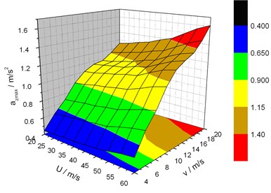
Fig. 12Maximum lateral acceleration response of the vehicle vs. vVand U-
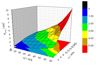
Fig. 11 shows that lateral acceleration of the bridge increases with the vehicle speed and wind velocity. So does the vertical acceleration. When the vehicle speed and mean wind velocity are respectively 20 m/s and 60 m/s, vertical acceleration reaches 2.43 m/s2
According to acceleration standard, vertical acceleration value is below 0.5 g. However, when wind velocity is larger than 45 m/s and the vehicle speed larger than 20 m/s, or when wind velocity is larger than 55 m/s and the vehicle speed larger than 18 m/s, the lateral acceleration is beyond the limit, 0.14 g by TB10002.1-99 standard.
Vertical and lateral relative displacement maximum can be referred in Table 4. According to derailment geometric condition, 25 mm, 37.5 mm, when wind velocity is below 60 m/s and vehicle speed below 20 m/s, the vehicle is safe. It is noted that wheel-rail relative displacement errors do exist and thus stationarity indictor must be examined further.
From Fig. 12, the vehicle‘s lateral acceleration also rises with the two velocities. When the vehicle speed and mean wind velocity are 20 m/s and 60 m/s respectively, vertical acceleration reaches 9.68 m/s2. Vertical acceleration satisfies the similar trend and its maximum is 2.31 m/s2, far below the lateral value.
According to the vehicle running stationarity assessment standard, vertical acceleration maximum is out of reach of the threshold 0.7 g by GB5599-85 standard. However, when wind velocity is larger than 50 m/s and the vehicle speed larger than 18 m/s, or when wind velocity is larger than 55 m/s and the vehicle speed larger than 14 m/s, the lateral acceleration is beyond the limit, 0.5 g by TB10002.1-99 standard.
In summary: 1) Deflection-span ratio and acceleration indices are suggested to assess the bridge safety. That is, deflection-span is examined first, acceleration indices next. 2) Lateral acceleration of the vehicle and bridge probably go beyond the threshold, especially for the vehicle. 3) When the vehicle runs at the designed speed of 4 m/s and mean wind velocity less than 60 m/s, indicators are far less than the standard limit, which indicates the structural safety and running stationarity are good. And when on all rigid supports, the vehicle velocity can be raised to 8 m/s.
5.3. LRB’s influence on the response and structural safety
When mean wind velocity is below 60 m/s and the vehicle speed below 20 m/s, the maximum coupled vibration response of vehicle-bridge on all rigid supported and all LRB supported are compared in Table 5.
Table 5Comparison of the maximum vehicle-bridge coupled vibration response when the truss bridge rigid supported and LRB supported
Coupled vibration response results | Rigid | LRB | Standard limits |
Vertical static and dynamic deflection / mm | 11.1/32.7 | 13.3/35.3 | 36 |
Lateral static and dynamic deflection / mm | 9.78/11.5 | 14.2/15.0 | 18 |
Vertical acceleration of bridge/ m/s2 | 2.43 | 2.04 | 5 |
Lateral acceleration of bridge / m/s2 | 1.61 | 1.35 | 1.4 |
Lateral acceleration of vehicle / m/s2 | 9.68 | 4.64 | 5 |
Vertical relative displacement of wheel-rail / mm | 15.5 | 22.8 | 25 |
Lateral relative displacement of wheel-rail / mm | 19.2 | 21.2 | 37.5 |
It can be seen from Table 5, consistent to the model test results, LRB can reduce acceleration obviously. For example, in the above case, the vehicle and bridge acceleration decrease down the limit. However, LRB will increase lateral deflection and wheel-rail relative displacement which can be controlled down the limit by selecting proper type of LRB. In a word, if all rigid supported theme is changed into all LRB supported theme, vehicle speed can be raised to 20 m/s.
5.4. Structural safety assessment under seismic and operational wind load
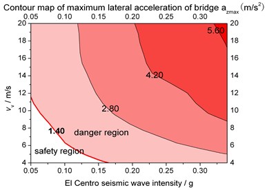
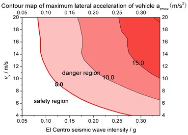
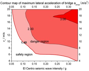
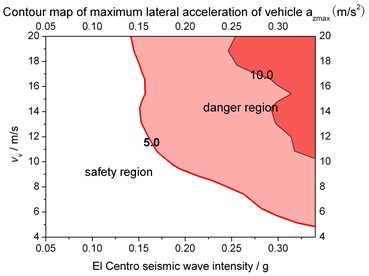
Maximum lateral acceleration response trend of the vehicle and the middle span of the truss bridge in two kinds of supports vs. seismic intensity and the vehicle speed are shown in Fig. 13 and Fig. 14.
Fig. 13Ground motion intensity and vehicle speed limits for structural safety when rigid supported
a) Max. lateral acceleration of bridge
b) Max. lateral acceleration of vehicle
Fig. 14Ground motion intensity and vehicle speed limits for structural safety when LRB supported
a) Max. lateral acceleration of bridge
b) Max. lateral acceleration of vehicle
By comparing Fig. 13 and Fig. 14 to Fig. 11 and Fig. 12, the sensitivity of the response to the seismic load is greater than the wind load. Illustrated in Fig. 13 and Fig. 14, safety zone of taking lateral acceleration of bridge as assessment indicator is smaller than that of the vehicle, which indicates that the bridge suffers more serious from seismic load. In contrast, Fig. 11 and Fig. 12 reflect the opposite regulation, which means the vehicle suffers more serious from wind load. That’s because ground motion is from the ground upwards while containers on the vehicle have a large frontal area. Meantime, LRB can obviously enlarge the safety zone.
By the El Centro wave excitation, when the vehicle speed is 4 m/s, seismic intensity threshold of the bridge on all rigid or flexible supports are 0.16 g and 0.33 g; when the vehicle speed reaches 6 m/s, seismic intensity thresholds of the bridge change to 0.10 g, 0.20 g; when the vehicle speed ranges from 8 to 10 m/s, the thresholds reduce to 0.05 g and 0.10g; at last, when the vehicle speed ranges from 10 to 20 m/s, the thresholds reduce to 0.05 g and 0.05 g again.
Due to the fact that the predominant period of El Centro wave is near to the first order natural frequency of the truss bridge, the seismic intensity and the vehicle speed limit under the El Centro excitation can be considered as the designed safety threshold. Furthermore, all flexible support is suggested as the truss bridge support type. In conclusion, a safety factor is taken into account, when the seismic intensity is below 0.3 g, 0.2 g, and 0.1 g, 0.05 g, the vehicle speed limit is suggested to be 4 m/s, 6 m/s, 8 m/s, 20 m/s respectively.
The above analyses were based on the conditions that the vehicles were running on the bridge during earthquake. Assume the vehicle stops in the position of middle span, still input El Centro wave and operational wind load, when LRB supported, the vertical and lateral deflection meets TB10002.2-2005 provisions. Therefore, ground vibration acceleration monitoring sensor can be set in the automated terminal, when the intensity limit reaches, the container vehicle decelerates to stop immediately to ensure the safety of the structure.
6. Conclusions
1) The results of model test and prototype simulation prove with each other, which confirm the method of applying free-interface CMS to obtain vehicle-bridge coupled vibration response, also validates LRB’s effects on vibration isolation as well as vehicle speed’s influence on coupled vibration response.
2) In the three-dimensional container vehicle-truss bridge distribution system for automated container terminal, vertical coupled vibration of the system is caused mainly by the vehicle moving load, and self-excitation is a major factor. Wind, seismic load will greatly enhance the lateral vibration. As vehicle speed, fluctuating wind average velocity or ground motion intensity increases, the response increases. And the sensitivity of the response to the seismic load is greater than the wind load.
3) On evaluating the truss bridge’s safety, first assessed by deflection-span ratio. Then, acceleration indices can be used to assess further. Moreover, the vehicle running stationarity shall be estimated by the lateral acceleration of the vehicle.
4) The truss bridge is suggested to be LRB supported. Thus, under wind load (wind velocity < 60 m/s) without seismic load, the vehicle can reach 20 m/s. Under operational wind and ground motion (EI Centro wave) excitation simultaneously, when the seismic intensity is below 0.3 g, 0.2 g, 0.1 g, 0.05 g, the vehicle speed can reach up to 4 m/s, 6 m/s, 8 m/s and 20 m/s respectively. However, when the intensity is up to 0.3 g, the vehicle must be stopped immediately.
References
-
Ouyang H. J. Moving-load dynamic problems: A tutorial (with a brief overview). Mechanical Systems and Signal Processing, Vol. 25, 2011, p. 2039-2060.
-
Au F. T. K., Cheng Y. S., Cheung Y. K. Vibration analysis of bridges under moving vehicles and trains: An overview. Progress in Structural Engineering and Materials, Vol. 3, 2001, p. 299-304.
-
Yang W., Zhang Z., Shen R. Modeling of system dynamics of a slewing flexible beam with moving payload pendulum. Mechanics Research Communications, Vol. 34, 2007, p. 260-266.
-
Wu J. J., Whittaker A. R., Cartmell M. P. Dynamic responses of structures to moving bodies using combined finite element and analytical methods. International Journal of Mechanical Sciences, Vol. 43, 2001, p. 2555-2579.
-
Chatterjee P. K., Data T. K., SuranaC. S. Vibration of suspension bridges under vehicular movement. Journal of Structural Engineering, Vol. 120, 1994, p. 681-703.
-
Dinh V. N., Kim K. D., Warnitchai P. Dynamic analysis of three-dimensional bridge-high-speed train interactions using a wheel-rail contact model. Engineering Structures, Vol. 31, 2009, p. 3090-3106.
-
Guo Weiwei, Xia He, Xu Youlin Dynamic response of long span suspension bridge and running safety of train under wind action. Engineering Mechanics, Vol. 23, Issue 2, 2006, p. 103-110, (in Chinese).
-
Han Yan, Xia He, Zhang Nan Dynamic response analysis of Train-Bridge system under non-uniform seismic excitations. China Railway Science, Vol. 27, Issue 6, 2006, p. 46-53, (in Chinese).
-
Guo Xiangrong, Zeng Qingyuan Analysis of critical wind speed for running trains on a schemed Yangtze River bridge at Nanjing on Jing-Hu high speed railway line. Journal of the China Railway Society, Vol. 23, Issue 4, 2001, p. 75-80, (in Chinese).
-
Zeng Qingyuan, Guo Xiangrong Vibration Analysis of Train-Bridge Time-Varying System: Theory and Application. China Railway Press, Beijing, 1999, (in Chinese).
-
Xia He, Zhang Nan Vehicle and Structure Dynamic Interaction. Second Edition, Science Press, Beijing, 2005, (in Chinese).
-
Li Yongle, Qiang Shizhong, Liao Haili 3-D coupled vibration of wind- vehicle-bridge system. China Civil Engineering Journal, Vol. 24, Issue 3, 2005, p. 61-64, 70, (in Chinese).
-
Li Y. L., Qiang S. Z., Liao H. L. Study on wind velocity field for the coupling vibration of wind- vehicle-bridge system. Acta Aerodynamica Sinca SINICA, Vol. 24, Issue 7, 2006, p. 131-136.
-
Xia He, Xu Youlin, Yan Quansheng Dynamic response of longspan suspension bridge to high wind and running train. Journal of the China Railway Society, Vol. 24, Issue 10, 2002, p. 83-91, (in Chinese).
-
Xu Y. L., Nan Zhang, He Xia Vibration of coupled train and cable-stayed bridge system in cross wind. Bridge Engineering, Vol. 24, Issue 4, 2006, p. 1389-1306.
-
Yang Y. B. Vehicle-bridge interaction analysis by dynamic condensation method. Structural Engineering, Vol. 121, Issue 6, 1995, p. 1636-1643.
-
Yau J. D., Yang Y. B. Vibration reduction for cable-stayed bridges travelled by high-speed trains. Finite Elements in Analysis and Design, Vol. 40, 2004, p. 341-359.
-
Lu Z., Yao H. L., Zhan Y. X., et al. Vibrations of a plate on a two-parameter foundation subjected to moving rectangular loads of varying velocities. Journal of Vibroengineering, Vol. 16, Issue 3, 2014, p. 1543-1554.
-
Cheng Y. C., Huang C. H., Kuo C. M., et al. Derailment risk analysis of a tilting railway vehicle moving over irregular tracks under wind loads. International Journal of Structural Stability and Dynamics, Vol. 13, Issue 8, p. 1101-1117.
-
Lu Kailiang, Qiu Huiqing, Mao Fei Free-interface component mode synthesis technique with link substructure as super-element. Journal of Tongji University, Natural Science, Vol. 38, Issue 8, 2010, p. 1215-1220, 1233, (in Chinese).
-
Shinozuka M., Jan C. M. Digital simulation of random process and its application. Journal of Sound and Vibration, Vol. 25, 1972, p. 111-128.
About this article
This work is sponsored by Shanghai Top Academic Discipline Project – Management Science and Engineering, this paper is supported by National Science Foundation of China (51405289), Doctoral Fund of the Ministry of Education (20123121120002), and also by Quality Standards and Metrology Research Project of the Ministry of Transport (2013-419-899-040 and 2014-429-899-110), Students Technology Innovation Project of Shanghai Municipal Education Commission.
