Abstract
The purpose of this paper is to research an effect of factors that are creating an imbalance of fan rotating blades and to estimate the possibility of compensation for this parasitic effect. For this purpose the measurement system including hardware and software was developed. Measurements of vibrations and dynamic pressure of rotating two-blades fan, blades profile and lift force parameters at various rotation speed were performed. This paper presents compensation possibilities when mechanical and aerodynamic imbalance occurs.
1. Introduction
Vibrations caused by mechanical and aerodynamic imbalance damage components of massive mechanical systems with rotors: helicopters, autogyros, industrial fans, wind turbines. Misalignment between a mass center and a geometric center of the rotor creates a mechanical imbalance [1]. An aerodynamic imbalance occurs when not identical blades [2] generate uneven lift force. Vibrations that occur in rotorcrafts also cause discomfort to passengers and pilot [3].
To keep rotor’s vibrations minimal rotorcrafts regular maintenance jobs on rotorcrafts are performed including balancing of a rotor. The most commonly used method for balancing called “Rotor Track and balance (RTB)” [4-5]. It consists of two stages. At the first stage while a rotorcraft is on the ground blades adjusted to make all blades tips fly on the same horizontal plane during rotation. Second stage is rotor’s vibrations magnitude and phase measurement during flight and detected imbalance are counterbalanced using external weights on the rotor. Measurement and counterbalancing performed several times to minimize vibrations caused by mechanical and aerodynamic imbalance to eligible level.
Rotorcrafts fly at various speeds, wind conditions, loads, however balancing weights position remain static despite changing flight conditions, additionally mechanical and aerodynamic imbalance in some cases can be inseparable by analyzing frequency spectrum of vibrations [6].
The aim of the research is to show that inequality of individual rotating blades geometry varying at different conditions, consequently aerodynamic imbalance is not constant and conventional balancing with weights is not effective.
Although our main research object is autogyro the initial research presented in this paper was performed on 2 blade fan. Mechanical and aerodynamic imbalance, likewise in rotorcrafts cause vibrations of industrial fans. Furthermore, for aims of the research is it possible to force mechanical and aerodynamic imbalance to the rotating system without violating the flight safety.
2. System of complex balance
The system consists of 2 blades fan supported by the frame and several sensors, data acquisition unit and PC with software for data processing, analysis and visualization.
The electric motor rotates 2 blades fan. Radius of the blades is 680 mm. The rotation speed is controllable with 3 presets: 2, 3, 4 Hz. The rotor with blades without supporting frame weights 8 kg. The lift force generated by this fan is 1/10 of the fan’s weight.
The system designed to be capable of measurement various parameters of rotating blades: lift force generated by blades, vibrations of the rotor, dynamic pressure generated by blades, profile of blades, rotation speed.
The load cell measures the lift force generated by rotating blades. 2-axis accelerometer mounted on the rotor measures the vibrations of the rotating rotor.
The microphone with calibration data utilized for measurement of dynamic pressure. The laser displacement transducer is utilized for measurement profiles of blades.
The magnetic field sensor and as marker used 5×5×5 mm neodymium magnet are for acquiring rotation speed of the blades. Another purpose of this sensor is to synchronize the start of rotation cycle with other measurement channels. This synchronization is important for further measured data processing and analysis. It allows averaging data between rotations and thus minimizing random measurement errors. It is also vital for acquiring phase information of fan vibrations and separating individual blade pressure, profile from primary measurement data.
Blades were marked as “A” and “B” for assigning individual measurement results after analysis.
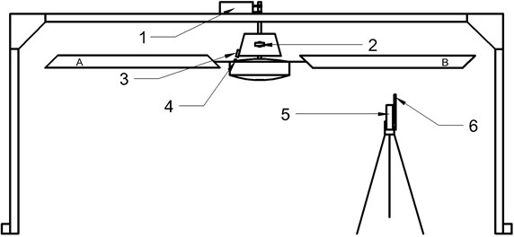
Fig. 1Measurement system. 1 – force (lift) sensor, 2 – 2 axis accelerometer, 3 – magnetic field sensor, 4 – magnet, 5 – laser displacement sensor, 6 – dynamic pressure sensor
3. The measurement of the blade’s profile
The aim of blades profile measurement is to evaluate fan’s blades angle of attack alteration at various rotations speeds, particularly if both blades behave similar while rotation speed is changing.
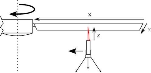
Measurements were performed using laser triangular displacement sensor with laser light directed to bottom surface of the blades (Fig. 2). The laser displacement sensor was fixed on the movable tripod. Blades profile scan was performed by moving it along -axis from tip of a blade to the center of the fan with a step of 50 mm. axis represents width of the blade. axis shows distance from the displacement sensor to surface of the blade.
Fig. 2Arrangement of the experiment and the measurement axis
Measurements at 10 points along axis were taken at 3 available rotation speeds: 2, 3, 4 Hz. Measurement data were acquired and saved during several rotations. Data processing involved: by synchronization assigning data segments to individual rotations, averring several rotations and extracting profile of “A”, “B” blades for individual scanning points. From blades profile data at individual points was combined 3D profile representation.
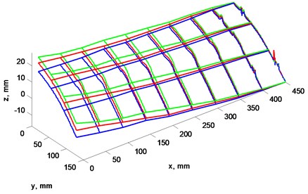
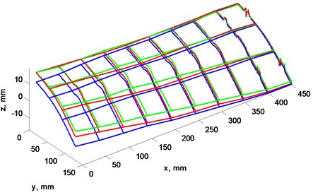
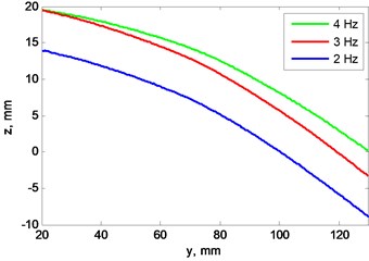
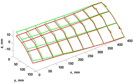
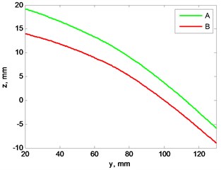
3D line grid (Figs. 3(a), 4(a), 5(a), 6(a)) represents results of measurement for easiest comparison between scans. 2D lines (Figs. 3(b), 4(b), 5(b), 6(b)) represents blades profile scan at the furthest section from center of the rotor where is the peak of blade bending.
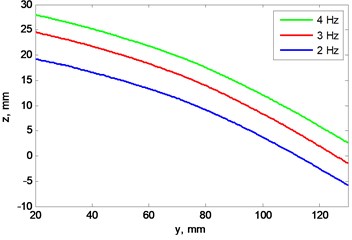
Figs. 3 and 4 show blades profiles at rotations speed equal to: 2, 3, 4 Hz. It shows how blades “A” and “B” tends to bend upwards as rotations speed increases.
Fig. 3a) Blade’s “A” profile scan at 3 rotation frequencies, b) view from left, plane cut at x= 0 mm
a)
b)
Fig. 4a) Blade’s “B” profile scan at 3 rotation frequencies, b) view from left, plane cut at x= 0 mm
a)
b)
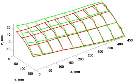
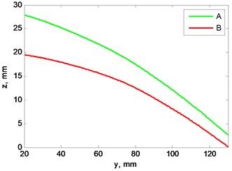
Fig. 5a) Blades profile scan at 4 Hz rotation speed, b) view from left, plane cut at x= 0 mm
a)
b)
Figs. 5, 6 illustrate differences between “A” and “B” blades profile when rotation speed is 2 and 4 Hz.
Results show that not only blades profile are not matching, but they have different rigidity and bend unequally while rotation speed is rising. Blade “A” vertical displacement is larger than blade “B” while rotation speed increase. This means, that blades even at lowest speed generate not equal lift force and this difference increases alongside rotation speed.
Fig. 6a) Blades profile scan at 2 Hz rotation speed, b) view from left, plane cut at x= 0 mm
a)
b)
4. The measurement of the blade’s pressure
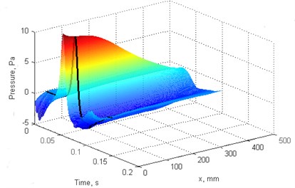
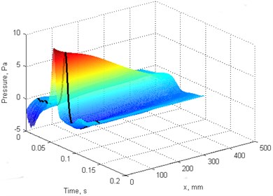
The aim of this measurement was to find link between blades profile and their generated dynamic pressure. Pressure scan was performed along axis with 50 mm step from blade tip to center of the fan at rotations speed: 2, 3, 4 Hz.
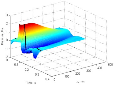
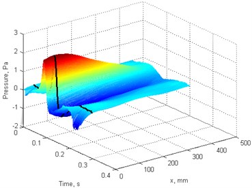
Fig. 7Blades pressure scan: a), b) f= 4 Hz, c), d) f= 2 Hz. a), c) blade “A”, b), d) blade “B”
a)
b)
c)
d)
Pressure scan results for individual blades at different rotation speed presented at Fig. 7. Pressure magnitude increases with rotation speed for each blade, however blade “A” magnitude is larger due stepper blade angle.
This final result of pressure scan was produced processing data in following order: during several fan rotations recorded measurement data subsequently assigned to individual blades and averaged to reduce random measurement errors, likewise processing blade profile data; 3D pressure scan combined from individual points and final graph smoothed for better presentation by interpolating data between existing points in axis.
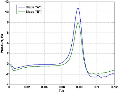
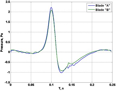
Pressure difference between blades is visualized better at plane cuts in Fig. 8.
Fig. 8Cut plane from blades pressure scan at x= 50 mm: a) f= 4 Hz, b) f= 2 Hz
a)
b)
A pressure difference between top and bottom blade surfaces generates a lift [7]. A difference between blade’s pressures indicates, that blades create not even lift force, aerodynamic imbalance occurs.
5. Interaction between mechanical and aerodynamic imbalance
A mechanical and an aerodynamic imbalance causes unwanted torque that leads to vibration of a rotor. Consequently follows presumption that force moments with opposite direction would counterbalance and minimize vibrations of a rotor. Condition for minimal vibrations:
where – torque created by aerodynamic imbalance, – torque created by mechanical unbalance.
The lift force difference between the first and the second blade creates torque . The external weight creates torque . The torques act around the point of fan’s consolidation. Torques are expressed further and visualized in Fig. 9:
where is difference between lift force of the blade “A” and the blade “B”, – distance between center of lift force and center of the fan.
is measured using load cell transducer. 0.84 N at 3.8 Hz; 0.37 N at 3.2 Hz. Typically center of lift force is located at 75 % of blade length [8]. For the fan used in measurements 0.51 m:
where is centrifugal force created by external mass , – distance between consolidation point and centrifugal force vector, – rotation speed of the blades. is distance between external weight and center of the rotor.
Mass of the weight used during experiment was 0.014 kg. 0.2 m, varies from –0.68 to 0.68 m.
Fig. 9Mechanical model of the system
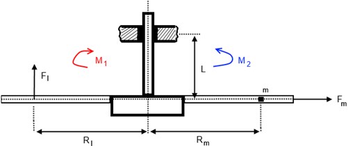
Fig. 10Positions of external weight, that creates mechanical imbalance
Based on Eqs. (1)-(4) theoretic model was created and calculations performed (Fig. 11(a)) which confirmed presumptions that torques created by aerodynamic and mechanical imbalance counterbalance at particular conditions, consequently experiment was performed.
External weight was moved from one blade edge to opposite during the experiment. It was placed at 8 fixed locations (Fig. 10) on the blades and the rotor. Locations were selected to reflected specific geometric points based on structure of fan.
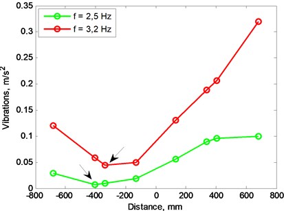
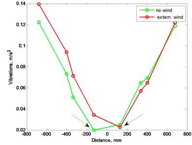
Fig. 11a) Lift force difference versus external weigh location (model), b) vibration level versus external weigh location, arrows pinpoint minimal values
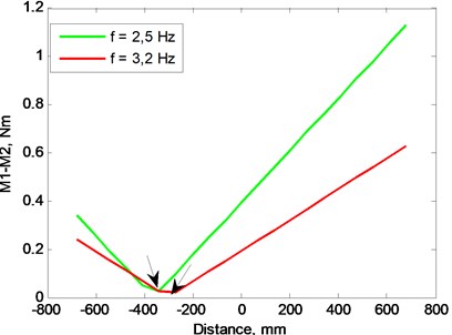
a)
b)
With each placement of the weight blades were rotated at 2 different speeds. Vibrations measurement results shows that there is point where level of vibrations are minimal, but location of that point changing with rotation speeds.
Results of measurements (Fig. 11(b)) were compared with theoretic calculations (Fig. 11(a)) which shows torque difference minimum near the same placement of the weight as during the experiment.
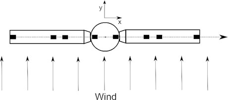
Imbalance experiment was repeated introducing new factor that impacts balance of the rotor – wind. This airflow should increase aerodynamic imbalance of the blades due not identical blade geometry.
Fig. 10 demonstrates direction of airflow. In Fig. 12 presented measurement results show that wind also influences location of weight where vibrations are minimal. The point where vibrations are minimal moved by one position to the opposite side when external airflow presented.
Fig. 12Vibration level versus external weigh location with external wind source, arrows pinpoint minimal values
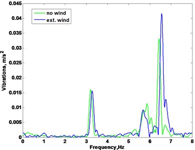
Frequency spectrum of vibrations is presented in Fig. 13 where fan rotation frequency is 3.2 Hz. It shows that spectrum component with double frequency of rotations increases significantly more than component that is equal to rotation frequency when external airflow impacts fan. Vibrations in direction are more sensitive to airflow impact, because of airflow direction in respect to fan and sensors position.
Fig. 13Frequency spectrum of fan vibrations: a) vibrations in x direction, b) vibrations in y direction
a)
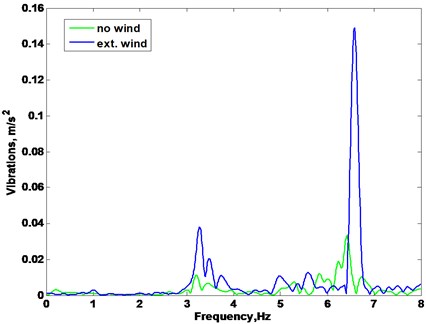
b)
6. Conclusions
Blades profile geometry comparison against blades at different rotation speeds shows that blades tends to change geometry at not equal rate. This phenomenon reveals the quality of the blades and the supporting mechanism.
The forced mechanical imbalance may compensate the aerodynamic imbalance and minimize system vibrations, however best location for the weigh placement moves due changed rotation speed and wind, so this way of compensating aerodynamic imbalance is not suitable for rotating system that works at not constant conditions.
Double rotation frequency component of vibration spectrum is sensitive to aerodynamic forces that occurs during blades rotation when external airflow impacts fan.
References
-
Adams M. L. Rotating Machinery Vibration – from Analysis to Troubleshooting, Second Edition. CRC Press, 2010, p. 406-410.
-
Rosen A., Ben-Ari R. Mathematical modelling of a helicopter rotor track and balance: theory. Journal of Sound and Vibration, Vol. 200, Issue 5, 1997, p. 589-591.
-
Ferrer R., Krysinski T., Aubourg P. A., Bellizzi S. New methods for rotor tracking and balance tuning and defect detection applied to Eurocopter products. American Helicoper Society 57th Annual Forum, Washington, 2001.
-
Johnson L. History: Helicopter Rotor Smoothing. http://www.dssmicro.com/theory/dsrothst.htm.
-
Robinson M. Helicopter Track and Balance Theory. http://www.aviationpros.com/article/10389059 /helicopter-track-and-balance-theory.
-
Gardels D. J., Qiao W. Simulation studies on imbalancef of wind turbines. Power and Energy Society General Meeting, 2010, p 1-5.
-
Dole C. E., Lewis J. E. Flight Theory and Aerodynamics: a Practical Guide for Operational Safety. New York, Chichester, Wiley, 2000, p. 35-38.
-
Mises V. M. Theory of Flight. Dover Publications Inc., New York, 1945, p. 145.
About this article

