Abstract
A new flexible supporting and fixing method for hybrid ultrasonic motor using longitudinal and torsional vibration modes is presented. A motor base is used to support and fix the motor, which has dual concentric bearings in opposite shell sides and a fixing slot. The axis of the motor has two extended parts outside the both sides of the motor. Once the motor has been assembled completely, the two extended parts of the motor axis will be inserted into the concentric bearings, which support the motor and restrict several degrees of freedom (DOFs) of the motor, such as the translational DOFs along and axes, the rotational DOFs around and axes. The motor has a flexible fixing sheet which placed near the piezoelectric ceramics, and the flexibility of the fixing is discussed by analyzing the thickness and the foot length of fixing sheet. The fixing sheet is fixed on the fixing slot with glue, which restricts the translational DOF along axis and rotational DOF around axis of the stator. The experiment results show that there is little influence on the motor working performance by using this supporting and fixing method; the motor can work smoothly and steadily and the maximum speed of the motor can exceed 2000 r/min.
1. Introduction
Ultrasonic motors [1-3] have been developed as a new concept of motor since the 1980’s. It can meet many new requirements for small and special motors because of their advantage of small size, light weight, compact structure, fast response, low noise, and no electromagnetic interference. Hybrid ultrasonic motors using longitudinal and torsional vibration modes (LTUM) [4-6] is one type of ultrasonic motors, and it has great practical and potential applications in optical instrument, medical device, and energy saving in buildings due to its large output power with small diameter. As the LTUM needs longitudinal and torsional vibration modes to work and the nodal planes of the two modes do not coincide, it is difficult to find a suitable orthogonal plane along the shaft to support and fix the motor, especially when the motor diameter is small. In recent researches, a nodal plane of the two vibration modes is chosen to set a rigid flange to support and fix the motor [7-10], but it does not consider the flexibility of the flange. When the motor diameter is large, the influence of the rigid supporting on the two vibration modes is small, and the motor can work properly, however, when the motor diameter is small, the effects of the rigid supporting on the two vibration modes cannot be ignored as the rigid supporting may significantly change the working modes, which will result in that the motor cannot work.
In order to make the LTUM with small diameter work properly in the application mentioned above, the working modes must be excited correctly, and then the install system must be considered. There are some supporting methods [11-13] for other types of ultrasonic motor, but none is suitable for LTUM with small diameter. In this paper, a new flexible supporting and fixing method for LTUM with small diameter is presented. Taking a LTUM with diameter in 5 mm as a research object, the flexible supporting and fixing structures are described, the dynamics simulations of the stator with and without fixing structure are analyzed by using ANSYS, and the vibration experiments for the stator and experiments for the whole motor with flexible supporting and fixing structures are also carried out.
2. Flexible supporting and fixing method
2.1. Structure of the motor
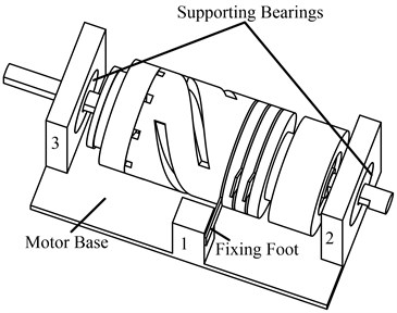
The LTUM with a mode converter is taken as the research object, as shown in Fig. 1. The motor has two parts, one is the stator, and the other is the rotor. The stator consists of mass, a group of PZT, and converter, and PZT is sandwiched by mass and converter, here the converter is used to convert the longitudinal vibration mode to torsional vibration mode. The diameter of the motor is 5 mm, and the length of the motor is 10.8 mm.
It is known that the modes of hybrid ultrasonic motors using longitudinal and torsional vibration modes (LTUM) are always the first longitudinal vibration mode (1st L-mode) and the second torsional vibration mode (2nd T-mode), as shown in Fig. 1. So the 1st L-mode and the 2nd T-mode are chosen as working modes for the research object.
Fig. 1Structure of the motor
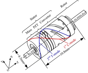
Fig. 2Modes of hybrid ultrasonic motors using longitudinal and torsional vibration modes (LTUM)
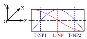
The 1st L-mode has one nodal plane which is recorded as L-NP, and the 2nd T-mode has two nodal planes which are recorded as T-NP1 and T-NP2, as shown in Fig. 2. We know that the fixing and supporting location for ultrasonic motor is best set near its nodal planes, but the three nodal planes of the motor are distributed along the axis direction of the motor, and there is no same nodal plane for the two modes. No matter which nodal plane is choosen for fixing and supporting, it has great effect on the other vibration mode. However, a method to fix and support the motor with flexibility which reduces the effect of the fixing and supporting on the vibration modes has been proposed in this paper.
2.2. Flexible supporting and fixing method
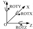
The degrees of freedom (DOFs) of the whole motor are the translational DOFs along , and axes (, , and ), and the rotational DOFs around , and axes (ROTX, ROTY, and ROTZ), as shown in Fig. 3(a).
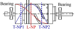
In the design of the motor, the dimensions of the mass and the converter are optimized by simulation, and there are two optimization goals, one is to adjust the frequencies of the two working modes to be consistent, another is to adjust the L-NP to be located near the plane between the PZT and the converter, as shown in Fig. 3(b).
It can be found that the location of L-NP is different from that of T-NP1 and T-NP2. T-NP1 and T-NP2 are located in the mass and the converter respectively, which cannot be used to set fixing device, so the fixing device should be set to L-NP. In the method, an annular copper sheet with a long foot is set between PZT and the converter, which has suitable thickness to possess flexibility. If the foot of the sheet is fixed, the and ROTZ DOFs of the stator will be restricted. However, the , , ROTX and ROTY DOFs of the stator must to be restricted, and the ROTZ DOF of the rotor should be free, then the motor can work properly. To solve this problem, two bearings are used to support two ends of the motor shaft, as shown in Fig. 3(b).
Fig. 3DOFs of the motor and the supporting method
a)
b)
Fig. 4Motor base and flexible supporting and fixing structure
2.3. Flexible supporting and fixing structure
The motor should be assembled in a motor base, as shown in Fig. 4. The motor base in Fig. 4 is a simplified structure, which is used to explain the supporting and fixing structure. In the motor base, there are three columns, the first column is used to fix the fixing foot, which is glued to the column, and the second and third columns are used to set two bearings, the motor shaft is supported by two bearings. The key design issue is how to design the fixing foot to insure the fixing structure has little influence on the motor working modes and enhance the performance of the motor.
The structure of the fixing foot is shown in Fig. 5, the foot width is set as 1mm, and the foot length and the thickness of the fixing foot is variable parameters which will be designed to get suitable value for the motor fixing design requirement. The fixing hole is used to fix the motor to the base. The fixing foot has its own resonant vibration, and the expected vibration modes are shown in Fig. 6.
Fig. 5Structure of the fixing foot
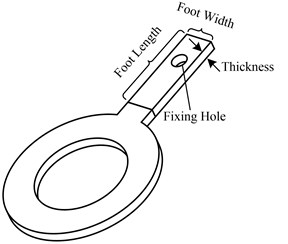
Fig. 6Vibration modes of the fixing foot
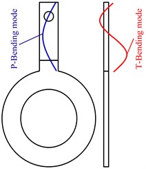
The two expected vibration modes for the fixing foot can be realized by designing the dimensions of the fixing foot, the foot length and thickness should be in a reasonable range; otherwise the two expected vibration modes cannot be appeared. The concrete design will be shown in Part 3 in this paper. These two vibration modes will be used for the fixing and supporting, one is foot bending mode in the plane (P-Bending mode), and the other is the foot bending mode along the direction of the thickness (T-Bending mode). The frequencies of these two modes must match the working modes of the motor. The fixing hole should be placed near the nodal point of the two modes, as shown in the Fig. 6. The design goal is to get suitable foot length and thickness to make the vibration displacement of the point on the contact surface of the stator maximum.
3. Simulation and analysis of flexible fixing
3.1. Simulation of the motor
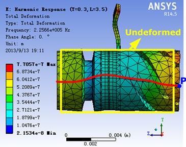
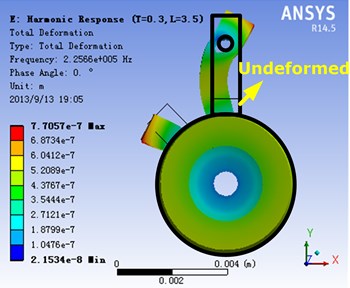
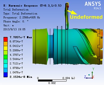
The simulation of the stator is carried out by using software ANSYS. The working mode of the stator is shown in Fig. 7. The 1st L-mode and the 2nd T-mode are coupled with each other, and the fixing sheet is placed near the nodal plane of the 1st L-mode. It can be found that the fixing foot also vibrates while the stator vibrates.
Fig. 7Simulation of the stator vibration
Next, the vibration of the fixing foot will be taken as research object. The simulations of P-Bending mode and T-Bending mode are shown in Fig. 8(a) and Fig. 8(b). As mentioned above, the P-Bending mode and T-Bending mode has nodal point respectively, and there is one area which contains the nodal points of the P-Bending mode and T-Bending mode simultaneously. Then the fixing hole must be placed on that area for the motor fixing and supporting, and then little disturbance will be applied on the stator working mode.
Fig. 8Simulation of the fixing foot vibration
a)
b)
3.2. Analysis of the fixing foot
Reference [4] gives the motor output stall torque of LTUM, which can be expressed as:
Eq. (1) can be simplified as:
where and are the vibration amplitudes of the point P in the direction of and , respectively; and are constants, which are independent of and . From Eq. (2), it can be found that the stall torque of LTUM is related with and , so and are the key objectives in this analysis. To get larger stall torque, and should be as large as possible.
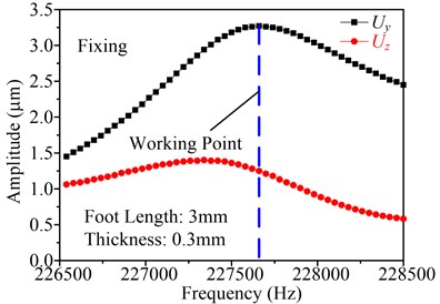
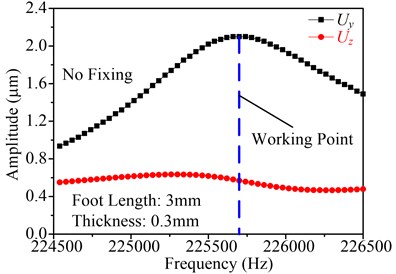
Taking the foot length and thicknesses of the fixing sheet as research object, the working frequency and the vibration amplitude of the point P (as shown in Fig. 7) on stator end surface can be gotten by using software ANSYS. As an example, the foot length is setting as 3 mm and the thickness is setting as 0.3 mm, and are shown in Fig. 9(a) and Fig. 9(b), in which the Fig. 9(a) shows the frequency response with fixing, and Fig. 9(b) shows the frequency response with no fixing. It can be found that the motor working frequency with fixing is large than that with no fixing, and the vibration amplitudes of the point P in the direction of and with fixing are also large than that with no fixing. With the above-mentioned equations, it also indicates that this supporting and fixing method is effective, which will enhance the motor output performance rather than decrease the performance.
Fig. 9Frequency response of the point P in the direction of Y and Z
a)
b)
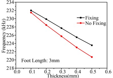
Next, the influence of the foot length and thicknesses on and is discussed. Fig. 10 shows the influence of thicknesses on , and working frequency, in which the foot length is setting as 3 mm. Fig. 10(a) shows the influence of thickness on motor working frequency and Fig. 10(b) shows the influence of thickness on , , both of them contain two boundary conditions, with fixing and with no fixing. In Fig. 10(a), it is observed that the motor working frequency will decrease by the augmentation of thickness in both boundary conditions, and the motor working frequency with fixing is larger than that with no fixing. Furthermore, when thickness increases, the difference between the working frequencies under two boundary conditions become large. However, small difference between the two working frequencies is the design objective, so the thickness cannot be large.
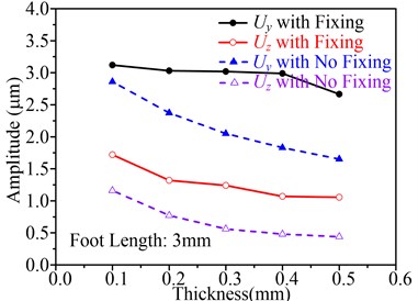
Fig. 10(b) shows the influence of thickness on and . First, it can be found that the and with fixing are large than that with no fixing; second, when the thickness increases, the and under two boundary conditions decrease; third, compared with the and with no fixing, the and with fixing changes smoothly. So the thickness should be small to enhance the performance of the motor.
In conclusion, considering the stiffness to enhance the carrying capability of the motor, the thickness is set to 0.2 mm.
Fig. 10Influence of thicknesses on Uy, Uz and working frequency
a)
b)
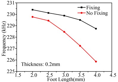
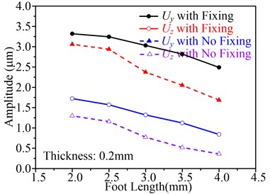
The other important parameter to effect fixing is the foot length. Fig. 11 shows the influence of foot length on , and working frequency, in which the thickness is setting as 0.2 mm. The change law of the curves in Fig. 11 is similar to that in Fig. 10. That is to say, using fixing and small foot length can enhance the performance of the motor. Therefore, considering the dimension of fixing hole, the foot length can be set to 2.5 mm or 3 mm. In the prototype, the foot length is set to 3 mm.
The above analysis indicates that the thickness and foot length play an important role in improving the performance of the motor and this flexible supporting and fixing method is effective to LTUM.
Fig. 11Influence of foot length on Uy, Uz and working frequency
a)
b)
4. Experiment
A prototype is presented, as shown in Fig. 12. The motor base is little different from Fig. 4, which is convenient to set up the system. To eliminate the installed stress of the fixing foot, which will cause the motor cannot work, an install method is presented. There is a slot cut in one side wall of the base, and its width is large than the thickness of the fixing foot, after the motor is set up in the two bearings, the fixing foot is adjust to place in the slot, and then using the glue to fill the slot, then the installed stress of the fixing foot can be eliminated.
Fig. 12Prototype
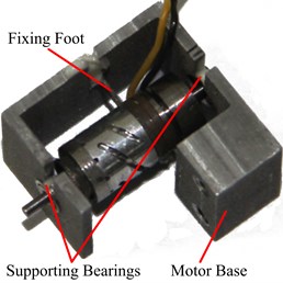
Fig. 13Frequency testing
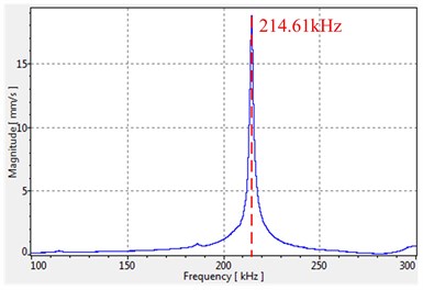
The thickness of the fixing sheet is set as 0.2 mm and the foot length is set as 3 mm in the prototype, then the scanning curves of the stator end surface with no fixing is tested using PSV-300F-B Doppler laser vibrometer, as shown in Fig. 13. It can be observed that the resonant frequency is 214.61 kHz. As mentioned in Fig. 7, the working mode of this type of motor is a couple mode of longitudinal and torsional vibration, so it is the working mode frequency.
When the motor is installed in the base, the tested working frequency with fixing in application is 203.4 kHz, which is little smaller than the working mode frequency of the stator. The reason of the difference from the simulation may be the rotor and axis added in the stator, which will change the working frequency.
The maximum speed of the motor tested can exceed 2000 r/min, which is a good performance for this type of motor.
5. Conclusions
A new flexible supporting and fixing method for LTUM is represented, the location and the flexibility of the fixing sheet are discussed, and the experimental investigation of proto-type is given.
The simulation analysis indicates that the thickness and foot length of the fixing sheet have obvious effect on resonant frequency and the vibration amplitudes of the point P in the direction of and , which will change the performance of the motor. The suitable thickness and foot length can be gotten from the simulation. Using the thickness and foot length got from the simulation, the prototype is presented, and the testing of the prototype is carried out. There is little difference between the simulation and experiment, and the reason is analyzed simply. Finally, the maximum speed of the motor tested can exceed 2000 r/min, which shows that this flexible supporting and fixing method is effective to LTUM.
References
-
Sashida T. Trial construction and operation of an ultrasonic vibration driven motor. Oyo Butsiuri, Vol. 51, Issue 6, 1982, p. 713-718.
-
Kumada A. A piezoelectric ultrasonic motor. Japanese Journal of Applied Physics, Supplement, Vol. 24, Issue 2, 1985, p. 739-741.
-
Zhao C. S. Ultrasonic Motors: Technologies and Applications. Science Press and Springer, Beijing, 2011.
-
Kurosawa M., Nakamura K., Ueha S. Numerical-analysis of the property of a hybrid transducer type ultrasonic motor. Ultrasonics Symposium, Vol. 1-3, 1990, p. 1187-1190.
-
Tomikawa Y., Adachi K., Aoyagi M., et al. Some constructions and characteristics of rod-type piezoelectric ultrasonic motors using longitudinal and torsional vibrations. Ultrasonics, Ferroelectrics, and Frequency Control, Vol. 39, Issue 5, 1992, p. 600-608.
-
Linshu Y. High power ultrasonic longitudinal-torsional compound transducers. Progress in Natural Science, Vol. 11, 2001 p. S45-S48.
-
Tsujino J., Ueoka T., Otoda K., et al. One-dimensional longitudinal-torsional vibration converter with multiple diagonally slittedparts. Ultrasonics, Vol. 38, Issue 1-8, 2000, p. 72-76.
-
Tsujino J., Ueoka T., Sano T., et al. Ultrasonic complex vibration welding system using 100 kHz one-dimensional longitudinal-torsional vibration converter. Ultrasonics Symposium Proceedings, Vol. 1-2, 2000, p. 695-698.
-
Tsujino J., Suzuki A. Load characteristics of ultrasonic motor with a longitudinal-torsional converter and various nonlinear springs for inducing static pressure. Ultrasonics Symposium Proceedings, Vol. 1-2, 2001, p. 545-550.
-
Tsujino J., Ihara S., Harada Y., et al. High frequency complex vibration systems using a complex vibration converter with diagonal slits. Ultrasonics Symposium Proceedings, Vol. 1-2, 2003, p. 699-702.
-
Lee H. M., Kim W. S., Yun C. H., et al. A high power and precision ultrasonic linear motor with lateral flexible supports. Towards Synthesis of Micro-/Nano-Systems, Vol. 5, 2007, p. 101-106.
-
Massad J. E., Washington G. N., Sumali H. Orthotropic deflection model for corner-supported plates with segmented in-plane actuators. Smart Structures and Materials 2005: Modeling, Signal Processing, and Control, 2005, p. 503-514.
-
Yun C. H., Kim W. S., Cha H. R., et al. Ultrasonic linear motor with a high stiffness support mechanism for precision control. High-Performance Ceramics V, Vol. 1-2, 2008, p. 368-372, 204-207.
About this article

The work was supported by National Natural Science Foundation of China (Grant Nos. 51205203), the Fundamental Research Funds for the Central Universities (No. 56XZA13051).
