Abstract
So as to improve the noise reduction performance and the optimization efficiency of the muffler, an optimization design method based on acoustic transfer matrix and genetic algorithm was proposed in this paper, wherein the transmission loss at certain frequency was treated as the optimization objective, and each structural dimension of the muffler as the design variable, the structural optimization design was conducted through genetic algorithm, thus the optimal solutions were eventually obtained; Moreover, single objective optimization and multiple objective optimization were successively performed, with the results compared with each other, through which it could be demonstrated that the result of the latter was superior to that of the former, concretely, the noise was reduced by 21.32 dB.
1. Introduction
With the rapid development of automobile industry, environmental pollution and noise pollution resulted from gas exhaust have become two major emission problems [1]. The exhaust noise control is principally achieved by the performance optimization of the exhaust muffler; as a consequence, a simple and effective optimization design method of the muffler exhibits a significant role on the exhaust noise reduction. Muffler optimization designs were conducted by scholars both at home and aboard through the transfer matrix method, the finite element method, the finite differential method and the boundary element method, etc. [2-4], through which certain effects were eventually obtained, however, most of them were limited to the fact that the transmission loss at certain frequency was treated as the optimization objective, although the noise amplitude at the optimized frequency was reduced, the overall noise didn’t achieve the optimal. In this paper, a multi-objective optimization design method of the muffler based on acoustic transfer matrix and genetic algorithm was put forward, wherein each structural parameters of the muffler were optimized and the overall transmission loss of the exhaust noise was remarkably improved, thus an obvious noise reduction effect of the muffler was exhibited.
2. Exhaust noise measurement and result analysis
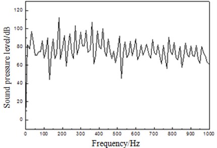
The measuring points of the exhaust noise were arranged as per the requirements of GB4759-1995, and the measurement range started from 1000 r/min to the rated rotational speed 1800 r/min, with the measurement interval of 200 r/min; the test system for the experiment was gathered by a sound testing system produced by LMS Corporation. Its signals were received by a sound pressure sensor; finally, it could be obtained from the experimentally measured data that the exhaust noise of the engine reached the highest – 118.64 dB at the rated rotational speed; Subsequently, optimization design of the muffler targeted at the exhaust noise frequency spectrum at the rated speed was performed, with the exhaust noise at the rated speed shown in Fig. 1.
As could be seen from Fig. 1, obvious peaks (all above 100 dB) of the exhaust noise sound pressure level occurred at 180 Hz, 270 Hz and 360 Hz, etc., and it reached the maximum 112.09 dB at 180 Hz.
Fig. 1The exhaust noise at rated speed
3. Acoustic transfer matrix model and model verification of muffler
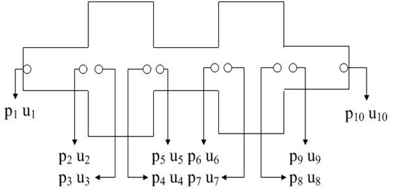
In this paper, the secondary reactive muffler was employed for the exhaust noise control of the engine, which was composed of 5 acoustic parts and 3 types of acoustic components, i.e. straight tube, expanding tube and shrinkage tube, respectively, with its outline shown in Fig. 2. And the node sound pressures - and the acoustic particle velocities of the whole muffler were shown in Fig. 3.
Fig. 2The outline of a muffler
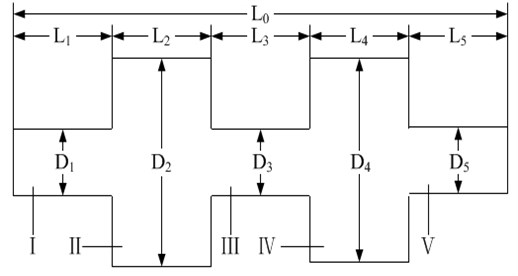
Fig. 3Acoustical nodes of a muffler
Based on the plane wave theory and with the average gas flow velocity in the tube taken into consideration, the continuity principle [5-7] of sound pressure and acoustic volume velocity at abrupt-changing cross section was utilized to obtain the acoustic transfer matrix expression of the muffler.
3.1. Sub-structures of uniform straight tube
The acoustic transfer matrix expression between Node 1 and 2 of the muffler was listed as follows:
The expression of the acoustic transfer matrix between Node 3 and 4 of the muffler was:
The expression of the acoustic transfer matrix between Node 5 and 6 of the muffler was:
The expression of the acoustic transfer matrix between Node 7 and 8 of the muffler was:
The expression of the acoustic transfer matrix between Node 9 and 10 of the muffler was:
3.2. Sub-structures of abrupt-expending tube
The expressions of the acoustic transfer matrixes between Node 2 and 3 as well as 6 and 7 were listed as following, respectively:
3.3. Sub-structures of abrupt-shrinking tube
The expressions of the acoustic transfer matrixes between Node 4 and 5 as well as 8 and 9 were listed as following, respectively:
The overall transfer matrix of the muffler could be obtained through matrix multiplication:
It could be simplified as:
And then the sound transmission loss (STL) of the muffler could be defined as:
wherein , -imaginary unit, – sound velocity, – circular frequency, , – sound wave frequency, – wave number, , – air density, , , , , – average Mach numbers of each acoustic components, , , , , , , , , , – sectional areas of each acoustic components of muffler at each nodes, , , , , – transfer matrixes of sub-structures of uniform straight tube, – transfer matrix of muffler system.
So as to verify the accuracy of the muffler transmission loss model established on the basis of the acoustic transfer matrix method, finite element simulation and experimental verification were both conducted on the muffler. The model was a single expansion cavity reactive muffler, with the inlet and outlet tube diameter of 48.59 mm, the expansion chamber length of 540 mm and diameter of 153.18 mm. The three-dimensional solid geometrical model for the muffler was built by ProE. And the model was imported to Hypermesh for geometry cleanup and mesh division. According to the requirements of the acoustic grid quality of the muffler, the Jacobian of the mesh element was larger than 0.7, body torsion angle was less than 0.8. The standard acoustic tetrahedral mesh model for the muffler was acquired as shown in Fig. 4, with 42368 elements and 25419 nodes. Simulation analysis on acoustic performance was carried out in acoustic simulation platform LMS.Virtural.lab, where unit speed excitation was applied at the inlet of the muffler, nozzle admittance condition was applied at the outlet, and other surfaces were default rigid walls. As a result, the transmission losses of the muffler were compared in Fig. 5, and refer to Reference [8] for its experimental result. See Fig. 6 for the illustration of the sound pressure levels of the muffler which was computed by means of finite element numerical calculation at the three points of 180 Hz, 270 Hz and 360 Hz.
Fig. 4Acoustical finite element mesh model of muffler
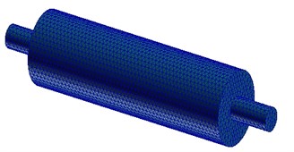
Fig. 5Transmission loss curves of muffler
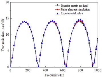
As could be seen from Fig. 5, within the frequency range under research, the transmission loss of the muffler obtained through the acoustic transfer matrix method proved favorably consistent with the experimental one and the finite element simulation one, which could therefore be employed for the transmission loss calculation of the muffler.
Fig. 6The illustration of the sound pressure levels at the three peak noise points
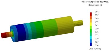
a) 180 Hz
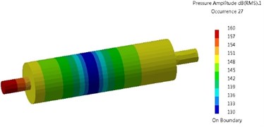
b) 270 Hz

c) 360 Hz
4. Application of genetic algorithm in muffler optimization design
The genetic algorithm (GA) was proposed by Professor J. Holland from America as early as 1975, which is a global optimization method on the basis of natural selection principle, natural genetic mechanism and adaptive search [9]. And the basic flow diagram of GA optimization was shown in Fig. 7.
Fig. 7The block diagram of GA optimization
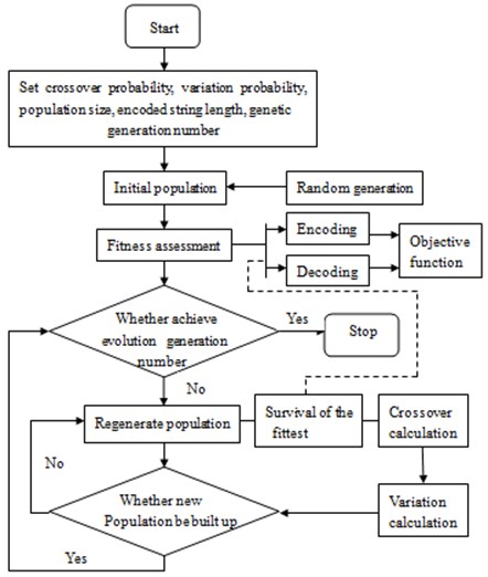
When GA was applied to the structural optimization design of the muffler, the steps were detailed as following:
1) Individual coding. Before the search, the geometrical dimensions of the muffler will be coded into fixed-length binary strings, and different combinations of these strings will constitute different search points in the search space.
2) Generation of initial population. strings will be randomly generated, with each string representing an individual, i.e. a geometrical dimension of the muffler.
3) Fitness calculation. With the transmission loss value as the fitness, calculate the transmission loss of the muffler.
4) Selection. Select out individuals with better fitness, i.e. individuals of the muffler with larger transmission losses.
5) Crossover. Exchange part of the chromosomes between the selected individuals at a certain probability to generate new descendant individuals.
6) Variation. Vary the selected individuals at a given probability to generate new population.
7) Judgment. Judge whether the new population is qualified for the constraint condition, if qualified, stop it, otherwise, shift to step 3) and continue.
5. Structural optimization design of the muffler
Due to the dimension limitation of the installation space, the muffler should be designed within the range of 1.5 m in length, 0.4 m in width and 0.4 m in height. The GA for the structural optimization of the muffler was completed through MATLAB programming, and so as to simplify the optimization design process, the inlet and outlet tube diameters were both set as 0.1 m, the same with that of the exhaust pipe, and the flow rate at the inlet of the muffler was set as 0.5 m3/s. Additionally, the value ranges of the structural dimensions of the muffler were: ; .
5.1. Single objective structural optimization of muffler
With the muffler transmission losses at 180 Hz, 270 Hz and 360 Hz as the optimization objectives, respectively, optimization calculations of the muffler structural dimensions were conducted through GA, with the objective function of:
The optimization results were shown in Table 1, wherein the maximum transmission losses were 42.10 dB, 42.14 dB and 42.14 dB, respectively. The muffler transmission losses after optimization were shown in Fig. 8, and the exhaust noises were reduced to 100.57 dB, 98.96 dB and 105.4 dB, respectively, decreased by 18.07 dB, 19.68 dB and 13.24 dB, respectively.
Table 1GA optimization results
Scheme | Frequency (Hz) | Results | ||||||||
(m) | (m) | (m) | (m) | (m) | (m) | (m) | (m) | STL (dB) | ||
1 | 180 270 360 | 0.399 | 0.100 | 0.400 | 0.050 | 0.467 | 0.466 | 0.467 | 0.050 | 41.10 |
2 | 0.400 | 0.100 | 0.400 | 0.274 | 0.315 | 0.315 | 0.314 | 0.282 | 42.14 | |
3 | 0.400 | 0.100 | 0.400 | 0.339 | 0.237 | 0.237 | 0.236 | 0.451 | 42.14 | |
Fig. 8The transmission loss of muffler after optimization
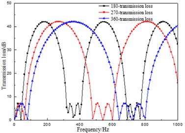
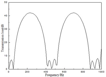
Fig. 9Transmission loss of muffler after multi-objective optimization
5.2. Multi-objective structural optimization of muffler
Based on the single-objective optimization results, the peak frequencies of 180 Hz, 270 Hz and 360 Hz were selected as the optimization sub-objectives, and through the weighting and normalization methods, an overall objective was determined to conduct multi-objective optimization, with the results shown in Table 2. The transmission losses of the muffler after optimization were shown in the Fig. 9. When the optimized muffler was applied for exhaust noise reduction, it could be decreased to 97.32 dB, reduced by 21.32 dB. The result proved superior to that considering single frequency.
Table 2Multi-objective GA optimization results
Results (m) | STL (dB) | |||||||||
180 | 270 | 360 | ||||||||
0.400 | 0.100 | 0.400 | 0.219 | 0.366 | 0.364 | 0.368 | 0.183 | 40.32 | 41.22 | 29.36 |
6. Conclusions
1) The transmission loss of the muffler was calculated out through the acoustic transfer matrix method, which proved favorably consistent with the experimental and finite element simulation results and laid the foundation for subsequent structural optimization.
2) On the basis of acoustic transfer matrix and genetic algorithm, single objective and multiple objective optimization designs of the muffler transmission loss were successively performed, and through structural optimization, the exhaust noises were respectively reduced by 18.07 dB, 19.68 dB and 13.24 dB through single objective optimization schemes, while 21.32 dB through the multiple objective one.
3) Compared with the single objective optimization, the multi-objective one based on GA could remarkably improve the optimization result and efficiency, which provided a new thought for the structural optimization of the muffler.
References
-
Gao H. W. Noise Control Engineering. Wuhan University of Technology Press, Wuhan, 2003, (in Chinese).
-
Yeh L. J., Chang Y. C., Chiu M. C., et al. GA optimization on multi-segments muffler under space constraints. Applied Acoustics, Vol. 65, Issue 5, 2004, p. 521-543.
-
Chiu M. C. Shape optimization of one-chamber perforated mufflers filled with wool using simulated annealing. Journal of Marine Science and Technology, Vol. 21, Issue 4, 2013, p. 380-390.
-
Liao R. D., Zuo Z. X. Developments in the finite element technique application for engine components. Transactions of Csice, Vol. 18, Issue 2, 1999, p. 190-197.
-
Munjal M. L. Plane wave analysis of side inlet/outlet chamber mufflers with mean flow. Applied Acoustics, Vol. 52, Issue 2, 1997, p. 165-175.
-
Chiu M. C., Chang Y. C. Numerical studies on venting system with multi-chamber perforated mufflers by GA optimization. Applied Acoustics, Vol. 69, Issue 11, 2008, p. 1017-1037.
-
Chiu M. C. Shape optimization of multi-chamber mufflers with plug-inlet tube on a venting process by genetic algorithms. Applied Acoustics, Vol. 71, Issue 6, 2010, p. 495-505.
-
Chen L. J. Mechanical Optimization Design Based on Genetic Algorithm. Machinery Industry Press, Beijing, 2006, (in Chinese).
-
Goldberg D. E. Genetic Algorithms in Search, Optimization, and Machine Learning. Reading Menlo Park, Addison-Wesley, 1989.
About this article

