Abstract
Reducing the bottom-hole differential pressure (BHDP) of a gas/oil well and so as to reduce the “chip hold-down effect” can significantly improve the rate of penetration (ROP). The fluid vortex and hydraulic jet methods are used to reduce the BHDP while the wellbore pressure is unchangeable to prevent wellbore instability. The depressurization theories of the two hydraulic pressure drawdown methods are studied. The structures, depressurization mechanism, depressurization capacity, and the current researches and developments of the hydraulic pressure drawdown tools, including the vortex tools and the jet hydraulic pressure drawdown tools (JHPDTs), are analyzed. Using field tests and flow field numerical calculation methods, the key factors which affect depressurization capacity of the vortex tools and the JHPDTs, and the design principles of the vortex bit and the jet pump bit are proposed. Different depressurization methods and structures are simulated, which shows the vortex and jet pump combination bit with 106 mm distance is preferable.
1. Introduction
In order to exploit oil and gas resources in the formation at great depth, a wellbore must be drilled from the land surface to the deep strata. The drilling tools, generally including the derrick, turntable, square kelly, drill pipe, drill collar and the drill bit, are needed to cut the formation rock. The rock is drilled by the teeth of the drill bit. A large amount of cuttings will be produced during wellbore drilling. To remove these cuttings from the bottom-hole to the surface, the drilling fluid is injected through the drill string while drilling, which carries the cuttings to the ground through the annular space between the drill string and the stratum. However, there is a very large bottom-hole hydrostatic pressure produced by the drilling mud in the bottom-hole, which prevents the cuttings from being carried away by the drilling fluid. Also, it leads to the repeated crush of the cuttings and decreases the ROP. This phenomenon is called the “chip hold-down effect”. For a 5000-meter-depth wellbore, the bottom-hole hydrostatic pressure is 55 MPa when the equivalent circulation density (ECD) is 1.1 g/cm3. The water outlet hole of the conventional bit is downward along the direction of well depth, which has an angle of 0°-60° with the bit axis. So the drilling mud flowing through the nozzle directly impacts on the bottom-hole and the cuttings is kept on the bottom-hole surface under enormous holding force, which is not conducive to the cuttings removal and the drilling efficiency. Especially during the drilling process in deep and ultra-deep well, a huge “chip hold-down effect” of the drilling fluid will greatly affect the timely removal of cuttings, which will cause a repetitive breaking, decrease drilling speed and increase the drilling cost.
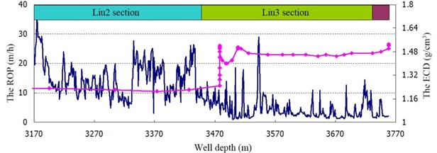
The BHDP is the bottom-hole hydrostatic pressure minus the formation pore pressure, which is one of the important factors that affect the ROP [1]. Laboratory tests and field applications show that reducing the bottom-hole differential pressure and so as to reduce the cuttings hold-down effect can significantly improve the ROP. In the Guanyinchang formation of the southwest Sichuan province, Zeng et al. had found that when the ECD of drilling fluid is 1.20-1.31 g/cm3 in 1981, 1.10-1.24 g/cm3 in 1982, and 1.03-1.18 g/cm3 in 1983, the ROP is improved by 34 % in 1982 and 84 % in 1983 compared with the value in 1981 [2]. Fig. 1 shows that under the same condition when the ECD decreases in the Liu3 section of Z12-2-3 well in the Western South China Sea oilfields, the ROP increases rapidly [3]. According to the U.S. Energy Infomation Administration (EIA) data, the number of producing gas wells is about 483 thousands in 2012 [4]. If the drilling speed can be improved by 10 % for each well and the drilling cost of each well is 10 million RMB, the drilling cost may be reduced by 483 billion RMB. So, decreasing the “chip hold-down effect” and increasing the ROP, the drilling cost can be largely reduced.
Fig. 1Relationship between the ROP and the ECD of Z12-2-3 well
In order to reduce the “chip hold-down effect” i.e. the BHDP, the air drilling, foam drilling and underbalanced drilling are developed. In the drilling processes, the bottom-hole can achieve near balanced or underbalanced conditions by reducing the ECD, and thus the “chip hold-down effect” is reduced and the stress condition of the bottom-hole is improved. The BHDP is reduced by reducing the ECD of drilling fluid. However, the ECD must meet the needs of safe drilling, that is to say the hydrostatic pressure of the drilling fluid should hold the in-situ pore pressure of the drilling formation to prevent the well blowout [5].
Many scholars have done a lot of researches on “how to reduce the BHDP” through a simple tool to reduce the “chip hold-down effect” in the bottom-hole in recent years [5-13]. They have designed many hydraulic pressure drawdown tools, such as the vortex tools, the JHPDTs and the pulsed jet tools to reduce the BHDP while maintaining the wellbore hydrostatic pressure. In this way, the wall of the wellbore is stable, and the bottom-hole differential pressure is reduced.
The vortex tools reduce the BHDP through the fluid vortex made from high speed rotation parts [9]. The returning fluid from the bottom-hole is the mixture of drilling fluid and hard cuttings with different shapes. In order to increase the life of the tools, the impact resistance and wear resistance of the rotation parts must be improved, and the sealing packer needs to be good enough to prevent the cuttings from coming into the annular space between the sealing packer and the production casing or the wall of the well bore. Using a turbine motor to drive a muti-stage pump, Bern et al. developed an ECD reduction tool (ECDRT) which can reduce the BHDP by 2 MPa [7]. Xu et al. used reverse nozzles to develop a pressure drawdown joint which can improve the ROP by 12 % [6], and the joint developed by Du can improve the ROP by 20 % [14]. Zhu et al. proposed a vortex bit to reduce the BHDP, and the reasonable axial angle, radial angle, reverse flow ratio, rotation speed, and distance between reverse nozzle outlet and the bottom-hole surface of the vortex bit are given [9].
The JHPDTs use water jet technique to increase the velocity of the mixture of drilling fluid and hard cuttings, which helps the drilling fluid carry the drilling cuttings to the ground. Yang et al. designed a reverse nozzle on a conventional polycrystalline diamond compact (PDC) bit, and the ROP can be improved by 40 % compared with the conventional PDC bit [15]. Another type of JHPDT is the water jet tool equipped with some jet pumps. This kind of JHPDTs can be classified as wellbore UBD jet pump [8, 16-20], jet pump joint [21] and jet pump bit [22-24]. They need no high speed rotation parts, but the individual power fluid is needed to drive the jet pump.
The NPPDTs create a cycled negative pulsed hydraulic jet to reduce the BHDP. It doesn’t need any high speed rotation parts and develops quickly in recent years for its good performance [25]. The hydroPulse™ drilling system [5, 26], the “SLPMC” mechanical-blocking hydraulic pulse tool [27], the hydraulic pulsed cavitation jet generator [28] and the Waltech NPPDT [29], etc. are commonly used.
This paper mainly analyzes the main aspects of the pressure drawdown methods, structure features, laboratory tests and field applications, etc. of the hydraulic pressure drawdown tools, studies the key points which affect their pressure drawdown capacities, and establishes their design principles, which provide a theoretical guidance for their development.
2. Mechanism of increasing ROP via decreasing the BHDP
Reducing the BHDP can significantly improve the ROP, which mainly results from two reasons: firstly, decrease the cuttings hold-down effect, and make the cuttings leave the well bottom in time to avoid repeated fragmentation; secondly, reduce the rock crushing strength and plasticity, and also improve the stress conditions of the bottom-hole to realize the rock failure under tensile stress condition instead of impact and shear stress conditions [30, 31].
2.1. Decreasing the rock crushing strength
In the conventional drilling process, the bottom-hole static hydrostatic pressure is slightly greater than the formation pore pressure. Supposing that the bottom-hole static hydrostatic pressure is and the formation pore pressure is , so the effective normal stress and horizontal principal stresses applied at some point on the bottom-hole rock surface are , and , respectively [5, 32]:
where is the effective stress coefficient, 0.80-0.95; and are usually bigger than . During the drilling process, the circulation of drilling fluid leads to a supplementary pressure in the bottom-hole, so the effective normal stress changes to:
Fig. 2Stress-strain curve of the silty claystone of the Z12-2-3well [31]
![Stress-strain curve of the silty claystone of the Z12-2-3well [31]](https://static-01.extrica.com/articles/15098/15098-img2.jpg)
a) 15 MPa peripheral pressure
![Stress-strain curve of the silty claystone of the Z12-2-3well [31]](https://static-01.extrica.com/articles/15098/15098-img3.jpg)
b) 30 MPa peripheral pressure
According to the three-dimensional (3D) Griffith criteria, if or , when the normal stress increases, the uniformity of the rock’s three principle stresses increases, which increases the rock plasticity and crushing strength. On the contrary, if the decreases, the rock crushing strength will decrease. Fig. 2 is the triaxial test result of the rock of the Z12-2-3 well in 2937.9 m, the rock yield stress, plasticity and crushing strength increase with the peripheral pressure [31]. Compared with the high permeability formation, the BHDP affects the ROP more remarkably in the tight stratum [33]. The reasons is: the drilling fluid can hardly infiltrate into the tight formation timely to balance the pressure difference between the upper and lower surfaces of the cuttings, which indicates that during the drilling process in tight formation, the ECD of the drilling fluid should be as lower as possible to achieve balanced drilling. Therefore, a lower bottom-hole pressure is good for decreasing the rock strength and increasing ROP. The limitation ECD of the drilling fluid is below the formation pore pressure. Under the negative BHDP, the bottom-hole rock is in the underbalanced drilling condition, which makes the rock failure by tensile stress instead of impact or shear stresses [34].
2.2. Reducing the “chip hold-down effect”
Supposing that there are some cuttings with independent matrix structure on the bottom-hole surface and the cuttings do not separate from the rock matrix in the drilling process. The normal hold-down pressure of the cuttings is , the pressure in the cleft between the cuttings and the rock matrix is . When the BHDP declines to the situation: , the direction of the total normal stress of the cuttings is upward. In this condition, the cuttings have a trend to leave the rock matrix and the “chip hold-down effect” disappears. On the contrary, when the , the BHDP and the “chip hold-down effect” increase.
2.3. Improving the ROP
The BHDP has an important influence on ROP and can not be ignored in the construction of the ROP equation. The influences of the BHDP on ROP were studied as early as 1968 [35], and then many equations are established to describe the relationship between the BHDP and the ROP [36-39]. In this paper, two of them are introduced: Bourgoyne and Young model, and modified Warren model.
Vidrine and Benit conducted the first field experiment that considered the BHDP as an independent factor on ROP at eight wells in south Louisiana [35]. The experimental wells depth range from 2400 m to 4500 m and their BHDP are between –6.412 MPa to 10.342 MPa. Based on the information obtained in this experiment, a model reflecting the relationship between BHDP and the ROP was established. Then, a new integrated model of the Gulf of Mexico was obtained, and the model is suitable for all the formations with continuous sedimentation. The model can be expressed as:
where represents the ROP, m/h; is the BHDP, MPa.
Bourgoyne and Young, based on the Vidrine and Benit model and the analysis of many filed data, pointed out that the relationship between the BHDP and the ROP was a linear one in the semi-log coordinate [40]:
where: is the ROP, m/h; is the ROP of zero BHDP, m/h; is a coefficient related with the rock properties.
Many laboratory drilling experiments of full-scale bit were carried out to modify the Warren model which considers the chip hold-down effect as an independent aspect [41-43]:
The expression reflecting the chip hold-down effect is:
where , , are the coefficients of bit; , , are the coefficients of the hold-down effect; is the rock strength under peripheral pressure; is the bit diameter; is the modified nozzle impact force; is the revolutions per minute (RPM) of drill bit; is the weight on bit; is the ECD of the drilling fluid; is drilling fluid viscosity.
2.4. Discussion
It is practicable and effective to increase ROP via decreasing the BHDP. In the drilling process, a lower ECD and a near-balanced drilling condition are favorable. In order to balance the in-situ formation pore pressure, the bottom-hole hydrostatic pressure of near-balanced drilling should be a little higher than the formation pore pressure. For an oil well, the bottom-hole hydrostatic pressure is bigger than the formation pore pressure by 1.5-3.5 MPa; for a gas well, the excess value varies from 3.0 MPa to 5.0 MPa. According to these principles, the near-balanced drilling always has a positive BHDP. The underbalanced drilling technology such as gas drilling and foam drilling has a negative BHDP. Compared with conventional drilling approach, the underbalanced drilling technology improves ROP by 4-8 times or even more. However, this technology needs large drilling safety control equipments and is restricted by the rock formation. For example, a water production formation is hard to use air drilling method for the cutting carrying problem.
3. Vortex depressurization method and vortex tools
3.1. Depressurization theory of vortex
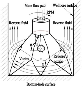
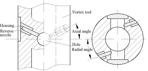
The high rotation speed of the vortex tool driven by a drill string or a turbine motor creates a strong vortex in wellbore, which pumps the bottom-hole fluid and thus reduces the BHDP [9]. There are three major types of vortex tools: the ECDRT, vortex joint and vortex bit. The ECDRT is fixed on the inner wall of production casing. The annulus between production casing and the ECDRT is sealed by a packer, and the BHDP is reduced by a multi-stage pump driven by a high rotation speed turbine motor. Vortex joint installed between drill bit and drill collar has several reverse nozzles. The drilling fluid flows upwardly through the reverse nozzles of vortex joint, its tangential velocity creates a vortex and its axial velocity helps to carry cuttings. The axial angle between bit axis and reverse nozzle axis of the vortex bit is changed from conventional 0°-60° to 90°-180° (Fig. 3). Partial drilling fluid flows upwardly from the reverse nozzles designed on bit, and creates a strong vortex on the bit face to reduce the BHDP, which is helpful to improve the return time and improve the ROP. The higher velocity of the reverse fluid can remove the cuttings timely, which can avoid bottom-hole surface from repeated fragmentation.
The depressurization value created by vortex is in proportion to the square of the rotational speed:
The depressurization value created by the axial momentum of reverse fluid is expressed as:
So, the total depressurization value can be expressed as [6]:
where and are the depressurization values reduced by vortex and reverse fluid respectively; is the drilling fluid density; is the radius of wellbore; is the radius of reverse nozzle outlet; is the fluid rotation speed; is the radial angle between flow direction/reverse nozzle axis and rotation direction; is the cross area of bottom-hole; is the flow rate of the reverse nozzle; is the axial angle between reverse nozzle axis and wellbore axis.
Fig. 3Depressurization mechanism of vortex bit
3.2. Vortex tools
3.2.1. The ECDRT
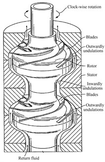
The ECDRT (Fig. 4) is designed to counter the increased fluid pressure in the annulus caused by friction loss, and the cuttings load by reducing the total hydrostatic head [7, 44, 45]. The tool consists of three sections. The top section is a turbine motor that draws hydraulic energy from drilling fluid and converts it into mechanical energy. The turbine drives the second section, a multi-stage pump (Fig. 5), which adds energy to the return fluid, creating the required pressure differential in the annulus. The helix blades of the multi-stage pump rotates in a clock-wise direction at a high speed, reduces the pressure of its housing and pumps the return drilling fluid mixed with cuttings [20]. The lower section are annular seals, which remain in constant contact with production casing, seal the annulus between the tool and the casing, and ensure that all return fluid and cuttings pass through the pump. The annular seals remain in constant contact with casing. The ECDRT is driven by the circulation of the drilling fluid. It couldn’t be used in air drilling or aeration drilling. It is designed to handle a wide range of drilling fluid with density up to 1.8 g/cm3, inclusive of drill cuttings, and with circulation rates up to 45.5 L/s. Its out diameter is 208.3 mm, and can be used in the casing from 244.5 mm to 339.7 mm. The out diameter of the turbine motor is 172 mm.
As the data of prototype test shows, the ECDRT has a minimum starting flow rate about 15.2 L/s. And the negative pressure increases steadily, by the form of the square, along with the increase of the flow rate. When the rate is 41.7 L/s, the pressure of the drilling fluid with a density of 1.5 g/cm3reduced about 2.89 MPa. While the pressure loss in the turbine and pressure recovery of pump is quadratic curves. The efficiency can be maintained at between 18 %-22 % when the flow rate is greater than 18.93 L/s.
The ECDRT was tested in southeastern Oklahoma oilfield in 2004 and 2006 respectively [7, 45]. In the first test, estimated ECD without the ECDRT for 1.17 g/cm3 drilling fluid was 1.19 g/cm3. The actual ECD with the ECDRT varied from 1.06 to 1.07 g/cm3. Thus the ECDRT reduced the ECD about 0.12 to 0.13 g/cm3, which means the BHDP was reduced about 1.77 to 2.07 MPa. Estimated ECD for the second test without the ECDRT was 1.25 g/cm3. The ECD with the ECDRT was 1.17 g/cm3, which showed about 0.08 g/cm3 ECD reduction. That is to say, the BHDP was reduced about 2.02 MPa. However, the ECD data began unsteadiness after 7 to 10 hours since the ECDRT started to be tested in the two tests. The tool’s performance began to decline.
Fig. 4The ECDRT
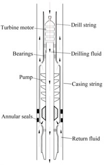
Fig. 5Multi-stage pump
3.2.2. Vortex joint
Reed designed a fixed-flow tool positioned at between the mud motor and the drill bit to reduce the hydro-static head near or around the bit [46]. The upper body portion includes a satellite gear member to force the relatively rotation of drill string and outer wall of tool. The lower portion contacts with the wall through a flexible ring and seals the wellbore annulus so that the return drilling fluid only flows back from the inside of tools. The movement of fluid is similar to the ECDRT. The upper drilling fluid drives the tool to rotate and the mixed-flow pump pumps the drilling fluid in the bottom hole by rotation, then the antihypertensive effect is achieved. The tool is connected directly to the drill bit and thereby it requests that the rotational speed is not too high, which limits the antihypertensive effect. Meanwhile, the tool is placed in the bottom hole and easily is locked by chip off-falling or collapsed debris. This is the main reason the tool has not been popularized.
Fig. 6Downhole pressure reduction tool
Using a partial collar, Xu et al. developed a downhole pressure reduction tool (Fig. 6). The tool was made by drilling collar and had female buckle at both ends which connected to the drill bit and drill collar respectively. At both side of the joint, two nozzle chambers were processed along with the tangential direction. A nozzle was mounted in each nozzle chamber. The nozzle, with external thread and center hole, was mounted into the thread in the bottom of the jet, and was blocked by the circlip. The nozzle diameter is 5-9 mm, and its axial angle is 120°-150°, its radial angle is 0°-90°. It was used in light limestone formation from 2663.44 to 2763.86 m depth of the Sichuan basin Pingxi-1 well. It could raise the ROP by 12 % when the ECD was 1.38 g/cm3, and the cuttings particles were bigger and more representative.
Du also designed a downhole vertex tool installed between collar and bit, which is similar to the downhole pressure reduction tool [14]. Its reverse nozzle axial angle is -120° and radial angle is zero. When its rotation speed is 250 rpm, the depressurization value below reverse nozzle is 0.015 MPa. In Zhongyuan Oilfield Xinwen district, the vertex tool was applied in 1500 m of Xinwen 269-6 well and 2000 m of Xinwen 72-189 well, which show that the ROP was improved by 20 % and the erosion of the wellbore wall was little.
3.2.3. Vortex bit
3.2.3.1. Reverse nozzle roller bit
The bit has two jet nozzles and one reverse nozzle, whose axes are all parallel to the bit axis that means their axial angles are all 180° (Fig. 7) [47]. The bit body between each two roller cones is milled along the bit axis direction, and then three planes with 50 mm width were obtained. Over each plane, three holes with diameter of 30 mm connect to the main flow path. The center line of the hole connecting to the lower nozzle is 20 mm far from the sealing step of drill bit, and the center line of the hole connecting to the top nozzle is 35 mm far from the sealing step of drill bit. The diameters of the three nozzles are all 13 mm. The reverse nozzle roller bit was tested in four wells in the same formation. Under the same drilling parameters, the average ROP of 850 to 1600 m well depth was 5.5-8.78 m/h which is 2.8 times of the conventional roller bit, and the footage of this bit is 4.3 times of the conventional roller bit. Much more big cuttings were obtained, which decreased the sand content of drilling fluid.
Fig. 7Reverse nozzle roller bit
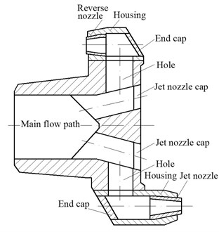
Fig. 8Reverse nozzle bit with double bodies
3.2.3.2. Reverse nozzle bit with double bodies
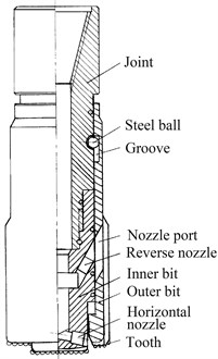
The reverse nozzle bit with double bodies consists of the outer-bit and the inner-bit (Fig. 8) [48]. The outer-bit connects with the joint by a steel ball, so, it can move up and down along the joint. The upper part of the inner-bit has a reverse nozzle whose axial angle is 120° and the lower part has a horizontal nozzle which is perpendicular to bit axis. The outer-bit moves to the lower end to prevent the radial jet of the horizontal nozzle from stabbing wellbore wall during tripping, and it moves to the topper end during drilling. When the fluid, ejected out from the horizontal nozzle, jets out along the bottom-hole, the pressure in the bottom-hole is weak and the ability to carry cuttings is strong. Also, there is no repeated fragmentation and the ROP has been improved. The reverse nozzle produces a vortex, reduces the BHDP and accelerates cuttings returning.
3.2.3.3. Reverse nozzle bit
Based on the conventional PDC and roller bit, Lamin and Graham designed a reverse nozzle bit (Fig. 9) that employs reverse flow nozzles through which a portion of the drilling fluid diverted [49]. This bit has several reverse nozzles and jet nozzles. The preferable reverse nozzle axial angle is between 135° and 180°. The bit is adapted to rotate in a direction of rotation, the reverse nozzle radial angle being between about 50° to about 75° opposite the direction of rotation. The reverse flow ratio of drilling fluid flowing through reverse nozzles divided by the total drilling fluid is about 15 % to 25 %. A short cylinder with 25-35 mm length is inserted and fixed into the reverse nozzle enhances drilling performance by creating “venturi effect”. The reverse flow nozzle outlet is placed at a distance of not more than about 100-150 mm from the bottom-hole surface. The effective action of partial upward fluid diversion creates a relatively lower pressure below the reverse nozzle outlet and also assists in or causes generation of reverse fluid. Upward spiral flow is created by the reverse nozzles placed with different angles. The reverse flow passages may be other shapes and configuration such as spirals and involutes and may have a circular, oval or other cross section.
Fig. 9Reverse nozzle bit
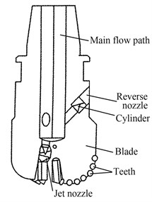
Fig. 10Combined-jet PDC bit
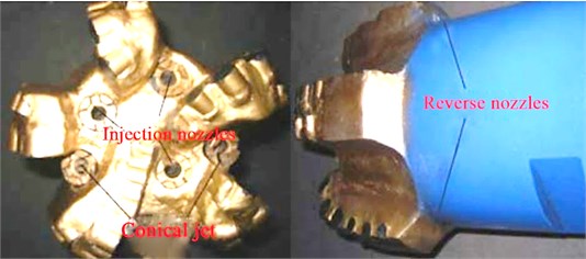
Yang et al. developed a combined-jet PDC bit to reduce the BHDP (Fig. 10) [15]. This PDC bit has two reverse nozzles, three injection nozzles and two conical jets. It is a typical reverse nozzle bit. The reverse nozzles are designed inside the two blades and their angles are both 180°. The bit was used in well Tuo 747. It could improve the ROP by more than 40 % compared with the neighboring wells using conventional PDC bits.
3.3. Discussion
1) The ECDRT widens the window to economically drill certain wells that today may be shelved [50]. The ECDRT can reduce the BHDP about 2.07 MPa, but its life is only about 10 hours. This tool is portable, and can be connected to drill string of not more than 213 m well depth through a short tripping. The return fluid from the bottom-hole is the mixture of drilling fluid and hard cuttings with different shapes and sizes, which can easily cause the helix blades failure with impaction and erosion, and annular seals failure with leakage. The ECDRT works at a high rotation velocity. In order to increase its life of the tools, the impact resistance and wear resistance of the rotation parts including the turbine motor, multi-stage pump and bearing must be improved, and the annular seals need to be good enough to prevent the cuttings from coming into the annular space of the annular seals and the production casing/wellbore wall.
Hannegan and Divine pointed that approximately 20-30 % of the known world’s offshore oil and gas resources are hard to be developed, due to excessive ECD when drilling [50]. The ECDRT provides a new way for the deep-water drilling wells when the ECD is decreased and drilling risk can be avoided, which can save time and money for the offshore oil and gas exploitation. Hariharan and Judge proposed a means to manage the ECD using a subsea pressure monitoring and control device such as a choke or bypass valve that is located at the mudline [51]. They explained that “The equipment may be thought in terms of being used as a ‘plug-n-play’ tool and could be run above the BOP’s, between the upper-annular and the flex-joint. In this manner, in the event of a pressure situation, the well is completely isolated from the riser. The return mud is directed through a subsea control device capable of applying back pressure to the well. The bottom hole pressure in the well is automatically managed and controlled during drilling and circulation utilizing field-proven devices. Maintaining bottom-hole pressure in this manner creates options to utilize lighter weight drilling fluids while still preserving desired safety margins”.
2) The vortex joint almost only reduces the wellbore pressure below the reverse nozzle in a small distance, so it should be installed closely to bit. It has no moving parts, and its structure is simple, which is easy to be realized. For the restriction of the rotation speed of drill string, the vortex joint can only reduce the wellbore pressure about 0.015 MPa below the reverse nozzle outlet, but the BHDP is almost unchangeable. So, how to improve the rotation velocity of the vortex joint is the key point to improve its performance.
3) The reverse nozzle roller bit is a special kind of the reverse nozzle bit. The reverse flow ratio of reverse nozzle roller bit is 33.3 %, it has good performance in the lower formation of not more than 1600 m, but its performance is still unknown in the deeper formations. The jet velocity of the horizontal nozzle of reverse bit with double bodies is in the radial direction, which helps the bottom-hole flow field carry cuttings rapidly, and thus improve the ROP. However, the reverse bit with double bodies has a moving outer bit which is not reliable during drill. So, this bit is still on the design stage. The reverse flow can be changed by the number and diameter of the nozzles, and there are no moving parts, which show that the reverse nozzle bit is feasible to reduce the BHDP and carry cuttings.
Zhu et al. used the RNG k-ε turbulence model to calculate the flow field of vortex bit [9]. They found that: the backflow below the reverse nozzle outlet is the main reason that decreases the vortex bit depressurization capacity, so, how to reduce the backflow is the design critical point. Increasing the axial angle, radial angle, flow ratio of reverse nozzle and bit rotation speed, and decreasing the distance between the reverse nozzle outlet and the bottom-hole surface can all improve the depressurization capacity of the vortex bit. When all the fluid flows upwardly, the vortex bit can reduce the BHDP about 0.2 MPa.
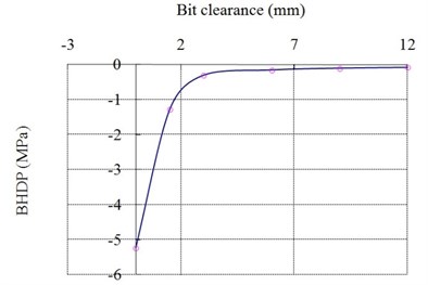
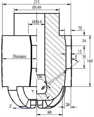
Using the same method and conditions, the critical factors that decide the depressurization capacity of the vortex bit are further studied in this paper. The calculation model is shown in Fig. 11. The vortex bit has five blades. There is a reverse nozzle outlet between each two adjacent blades. The reverse nozzles link the main flow path to the annulus between the bit and the wellbore surface. The reverse nozzle is shown is Fig. 12. is the radius of the reverse nozzle outlet; is the radius of the main flow path of the bit; is the distance between the reverse nozzle outlet and the bottom-hole surface; is the radial angle of reverse nozzle inlet; is the radial angle of reverse nozzle outlet. The influence of the bit clearance (the wellbore radius minus the bit radius) on the BHDP is shown in Fig. 13. The BHDP is negative which shows that the formation in-situ pore pressure is larger than the hydrostatic pressure. The BHDP increases rapidly to –0.2 MPa while the bit clearance increases. When the bit clearance increases from 0 mm to 3 mm, the BHDP increases from –5.3 MPa to –0.2 MPa. When the bit clearance is above 9 mm, the BHDP keeps at about –0.2 MPa. The numerical simulation agrees with the results of the experiments conducted by Sun very well [24], which shows that the numerical simulation results are reliable and accurate. So, how to seal the bit clearance is the critical point to improve the performance of the jet pump bit.
Fig. 11The 8 1/2” reverse nozzle bit meshed by tetrahedral meshes
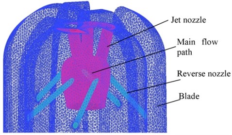
Fig. 12Reverse nozzle axis
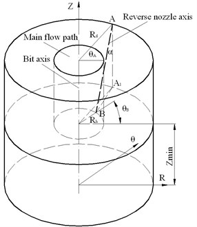
Fig. 13The relationship between bit clearance and the BHDP
Increasing the RPM of the vortex bit can increase the bottom-hole vortex intensity, so as to decrease the BHDP. Some additional smaller blades are designed on the bit, the spoon-shape blades produce the BHDP of –0.2 to –0.3 MPa (Fig. 14) and the plane-shape blades produce the BHDP of –0.22 to –0.43 MPa (Fig. 15). The minimum BHDP of the vortex bit with plane-shape blades is about two times of the vortex bit, which shows that this is a useful way to increase the depressurization capacity of the vortex bit.
Fig. 14The BHDP of the vortex bit with small spoon-shape blades
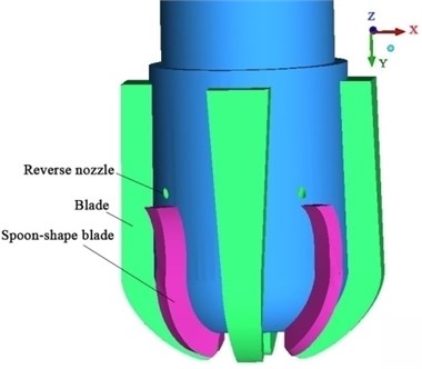
a) Vortex bit with spoon-shape blades
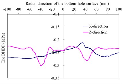
b) The BHDP of radial direction
Fig. 15The BHDP of the vortex bit with small plane-shape blades
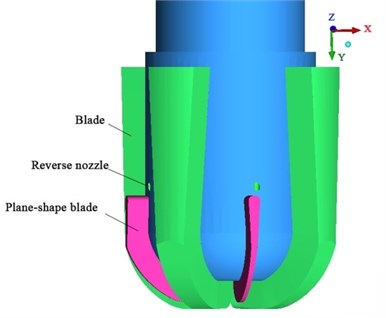
a) Vortex bit with plane-shape blades
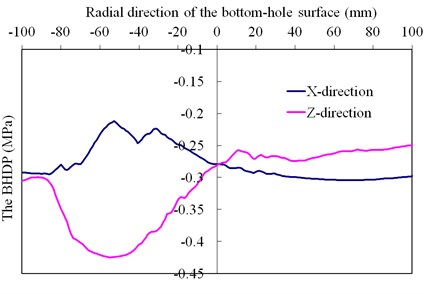
b) The BHDP of radial direction
After calculating the BHDP of 32 kinds of vortex bit structures, the design principles of vortex bit are proposed:
1) A bigger angle is recommended, and the optimal value is suggested as 150° to 180°. To reduce the backflow area of the fluid, the bit clearance should be smaller than 3 mm.
2) A greater angle enhances the strength of vortex, and so as to decrease the BHDP. However, the velocity of the drilling fluid in the axial direction is smaller, which is detrimental to cuttings carriage. So the recommended range is 60°-75°.
3) With the permission of the drilling situation, the rotation speed of the jet pump bit should be improved as large as possible.
4) When the flow ratio of the reverse nozzle is 25 %, the negative pressure zone is in the wellbore annulus, and the bottom-hole surface is still in overbalanced condition, so we suggest that the flow ratio of the reverse nozzle is 30 %-40 % and the displacement of drilling pump is as large as possible.
5) The bigger the is, the smaller the negative pressure is, so a smaller distance should be chosen. However, when the distance is too smaller, for the existing of blades, the bit crown would be stabbed by the fluid impaction, so an enough bit crown thickness should be designed and 100 mm-140 mm height of is preferable.
6) Some additional smaller blades are recommended to increase the vortex intensity.
4. The hydraulic jet depressurization method and the JHPDTs
4.1. Depressurization theory of the hydraulic jet
The hydraulic jet depressurization method uses jet pump or peripheral nozzle jet pump in the well-hole or bottom-hole to reduce the fluid pressure and carry cuttings. The jet pump consists of reverse nozzle, suction pipe, throat and diffuser (Fig. 16). Compared with the jet pump, the suction pipe and throat of the peripheral nozzle jet pump are in the same axis. Because of this the pumped fluid will not change its direction when it comes into the throat. So it is more suitable for pumped fluid that has higher solid concentration and larger size [52]. The working process of the jet pump: low pressure and high speed power fluid comes from the reverse nozzle, and draws the cuttings (i.e. suction fluid) in the bottom-hole to the throat. In this way the pressure of the bottom-hole is kept at a lower situation and the BHDP is reduced; the power fluid and the drilling fluid mixed with cuttings exchange between momentum in the throat; when the cuttings with high speed come into the diffuser, their speed decreases and pressure increases [53]. Then it is easy to pump them out.
1) The working principle of the hydraulic jet venturi pipe can be expressed by Bernoulli’s equation and continuous equation. The equations of 0-0 and 1-1 sections are expressed as:
Fig. 16Structural of jet pump
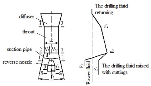
2) The power fluid has no backflow and the power fluid and the suction fluid don’t mix between 1-1 and 2-2 sections. The equations of 1-1 and 2-2 sections are expressed as:
3) Taking the throat as a control volume, the momentum equation of 2-2 and 3-3 sections along the bit axis direction is expressed as:
The energy equation of 2-2 and 3-3 sections is expressed as:
where , , , , , are the pressure, velocity, flow area, gravity, flow rate and local head loss through the section, and ; is the flow rate of the power fluid; is the jet pump number; is the coefficient concerned with the angle ; is the momentum loss caused by friction; is the non-uniform correction coefficient of 3-3 section; is non-uniform correction coefficient of energy; is the density of the discharge fluid; is the pressure loss in the throat. Using these equations, the depressurization capacity of the JHPDT can be simply calculated.
4.2. The JHPDTs
4.2.1. Wellbore UBD jet pump
4.2.1.1. Casing fixing
1) Independent jet pump
Hughes and Renfro designed an independent jet pump shown in Fig. 17 [17, 18]. This jet pump is fixed at the 9 5/8” production casing. An inner casing is concentric with the producing casing and has a smaller diameter. The packer is used to separate the annulus from the lower well bore. The power fluid flows into the jet pump and the suction fluid flows into the inner annulus between the apparatus and drill string. When the jet pump begins to work, a single phase fluid flows into the annulus between the 9 5/8” production casing and 7” inner casing, and turns upwardly into the bladder fill zone. The bladder will expand when it contacts with the drill string. And then the bladder diverts the suction fluid within inner annulus and forces it to flow through the jet pump suction pipe. The transfer of momentum from the power fluid to the slow moving suction fluid in the throat can create a discharge pressure adequate to lift the combined fluids to surface. Suryanarayana et al. discussed the design process and the impact of the jet pump on creation of underbalanced conditions [54]. It is proved that the jet pump is feasible for a reservoir pressure as low as 0.48 g/cm3 ECD.
Fig. 17Casing fixing wellbore UBD jet pump
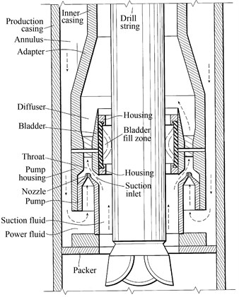
Fig. 18Concentric casing actuated jet pump
2) Concentric casing actuated jet pump
Based on the independent jet pump, Hughes and Renfro divided the inner casing into three parts and the jet pump into two parts, and thus developed a concentric casing actuated jet pump (Fig. 18) [16]. When the jet pump begins to work, the upper part of the inner casing actuated by power fluid moves downwardly to cause the diverter bladder to expand inwardly and create a seal around the drill pipe. In this way it diverts the suction fluid into the jet pump throat. When the upper part of the inner casing contacts with the middle part of the inner casing, the concentric casing actuated jet pump begins to work as an independent jet pump.
3) Helix hydraulic jet apparatus
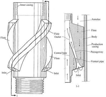
Hughes also designed a helix hydraulic jet apparatus (Fig. 19) [55]. The venturi pipe locates in the helix flute. The fluid flows downwardly through the out annulus to pass in a spiral direction between the flutes. The packer is used to seal the passage of the out annulus. The conventional slips lock the apparatus in position when there is an upward pull on the concentric inner casing. The lower pressure power fluid comes out of the outlet of the venturi pipe, and forms a vortex in the annulus between the inner casing and drill string reducing the pressure differential.
Fig. 19Helix hydraulic jet apparatus
4.2.1.2. Rotating jet pump
Fig. 20Hydraulic jet ECD reduction tool
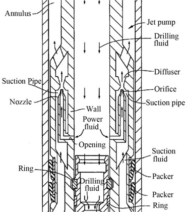
Fig. 21Packer – bearing hydraulic jet ECD reduction tool
Hosie et al. designed a hydraulic jet ECD reduction tool (Fig. 20) [8, 19, 20]. Both ends of the tool connect with drill string. The packer in the lower end of the tool seals the annulus between the tool and the production casing, and rotates and moves vertically along the inner wall of production casing. When the tool is in use, a part of drilling fluid comes through reverse nozzle of the jet pump as power fluid to pump the suction fluid; another part of drilling fluid flows downwardly through the inner hole of the tool to carry cuttings and cool bit. As the annulus is sealed by the packer, the drilling fluid containing cuttings, returning from the bottomhole, only flows upwardly along the tool. Under the action of the power fluid, the drilling fluid is pumped and speeded and then reduces pressure and carries rock.
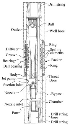
Combining the packer and rolling bearing, Hassen designed a packer – bearing hydraulic jet ECD reduction tool (Fig. 21) [56, 57]. This tool rotates with drill string through the rolling bearing. The packer is used to seal the annulus between the tool and the production casing and moves vertically on the inner wall of the production casing. The jet pump locates on one side of the tool, and a plurality of vertical bypasses locates on the other side. Most of drilling fluid flows downwardly through the bypasses to carry cuttings and cool bit, and the rest of drilling fluid is used to actuate the jet pump.
4.2.2. Jet pump joint
4.2.2.1. Annulus bypass peripheral nozzle jet pump tool
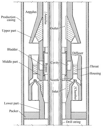
Association de Recherche sur les Techniques d’Exploitation du Petrol developed a depressurization drilling tool, which consists of upper sub, depressurization sub and depressurization diamond bit [58]. A separator acts as a bypass valve that diverts some of the drilling fluid to the annulus of the upper sub as power fluid to drive the jet pump. The rest of drilling fluid circulates through the annulus, across the bit face and back into the tool to carry cuttings and cool the bit. The returning drilling fluid mixed with cuttings is pumped to join the diverted fluid in the depressurization sub and both enter the annulus. Upper sub can be replaced by an inverser that provides the option of normal or reverse circulations.
Fig. 22Annulus bypass peripheral nozzle jet pump tool
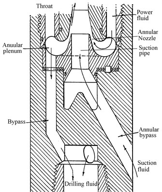
Fig. 23Annulus bypass peripheral nozzle jet pump tool
Hooper designed an annulus bypass peripheral nozzle jet pump tool (Fig. 22) [59, 60]. A modulating plug closely expands to the well bore diameter to form an annulus for external bypass of well fluid immediately above the drill bit. By an upwardly disposed peripheral nozzle jet pump with controlled suction of fluid from the bit, a reduced and/or underbalanced fluid pressure condition at the bit-to-bore bottom interface is established for operating the drill bit at an increased ROP while maintaining a higher pressure condition in the well bore annulus above the modulating plug controllably expanded by hydraulic pressure applied to operate the jet pump. According to flow patterns, this tool has five structures forming with a relevant conventional jet bit or a center discharge bit.
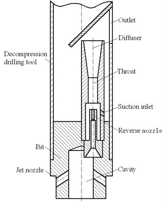
4.2.2.2. Normal circulation depressurization drilling tool
Zheng et al. designed a normal circulation depressurization drilling tool (Fig. 23), which doesn’t need a separator or a modulating plug to divert the fluid [61]. So its structure is much simpler than the two tools discussed above. The drilling fluid flows into the same cavity of the bit and the tool, and then the fluid automatically diverts into two flows: one flows downwardly to carry cuttings and cool bit through the jet nozzle, and another flows upwardly as power fluid to actuate the jet pump through the reverse nozzle. Laboratory test shows that when the tool is directly installed on bit, the diameter of reverse nozzle is Ø2.5 mm and the power fluid is 9 L/s, the BHDP is reduced by 0.45 MPa. However, when the tool is installed above 2 m from the bit, the BHDP is almost unchangeable.
4.2.3. Jet pump bit
4.2.3.1. Sun’s bit
Sun’s bit has four jet nozzles used for carrying cuttings and cooling bit, and four reverse nozzles used for actuating jet pump (Fig. 24) [24]. The outside of the bit body is an 8 1/2” cylinder that is arranged with many gauge teeth. The reverse and jet nozzles connect with the main flow path of the bit, and the reverse drilling fluid is determined by closing a certain number of jet nozzles. Numerical calculation and laboratory tests show that the optimal ratio of the throat diameter divided by the jet nozzle diameter is 1.8 to 2.5 which can obtain the maximum depressurization value, and the maximum pressure reduced by the jet pump bit is 1.86 MPa. When the confining pressure is 10 MPa, flow rate is 30 L/s, bit clearance is 1 mm, the throat diameter is 15 mm and the reverse nozzle diameter is 8 mm; the smaller the distance between the reverse nozzle outlet and bottom-hole surface is, the better the depressurization capacity is; the confining pressure has little effect on the depressurization capacity; when the ratio of the reverse flow rate divided by the downwardly flow rate increases, the depressurization value increases; bit clearance is the major factor that affects the depressurization capacity, for example, when the bit clearance is 2 mm, the BHDP is reduced by 1.22 MPa, and when the bit clearance is zero, the BHDP is reduced by 2.6 MPa.
Fig. 24Sun’s bit
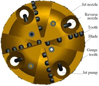
Fig. 25Underbalanced jet pump bit
4.2.3.2. Underbalanced jet pump bit
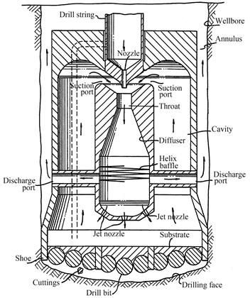
The underbalanced jet pump bit has a single jet pump which is concentric with the bit (Fig. 25) [22]. Drilling fluid mixed with cuttings in the cavity is pumped into the jet pump cavity by the jet pump, then its pressure increases; the cuttings are separated by the helix baffle, and along with some of the higher pressure they flow into the discharge ports and go out to the surface; the rest part of higher pressure flows downwardly through the depressurization nozzle to clean the bottom-hole and carry the cuttings to the cavity. So the reduced pressure drilling fluid can always flows back to drilling surface, however this bit is just in the conceptual design stage and needs further study.
4.2.3.3. Concentric nozzle jet pump bit
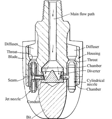
The external structure of concentric nozzle jet pump bit likes a conventional three blades PDC bit or a conventional tricone bit (Fig. 26) [23]. This bit has three vertical cylindrical nozzles. The upper port of each nozzle is used as a reverse nozzle while the lower port is used as a jet nozzle. The vertical nozzle is concentric with and has a smaller diameter than annular chamber. Drilling fluid flows through inlet conduit into the vertical cylinder, then part of the fluid flows upwardly through the upper port to actuate the jet pump. The rest part of the fluid flows downwardly through the lower port to clean the bottom-hole surface. The upper port and the annular chamber form a jet pump to pump the bottom-hole mixed fluid through the annulus between the lower port and the annular chamber.
Fig. 26Concentric nozzle jet pump bit
4.3. Discussion
1) Casing fixing wellbore UBD jet pump uses an inner casing to provide the flow passage for the power fluid, a packer to seal the annulus between the inner casing and production casing, a jet pump (Independent jet pump and concentric casing actuated jet pump) or a helix venturi pipe (Helix hydraulic jet apparatus) to reduce the well bore pressure. For abnormal reservoir with low pressure (the formation pore pressure is 0.48-0.84 g/cm3), Casing fixing wellbore UBD jet pump can achieve the underbalanced condition in the bottomhole while maintaining the pressure of upper wellbore [54]. So it has a very important practical significance. Currently, this tool is still in the phase of conceptual design, and its operation and supporting tools need to be done a lot of research works.
The wellbore UBD jet pump needs to be tripped in or out separately, so extra drilling procedures are added, which increases drilling cost and drilling auxiliary time. Some of the key issues of independent jet pump and concentric casing actuated jet pump are: 1) During tripping, in order to protect the bladder from impaction of drill string, the incline of drill string should be controlled, and a snubbing unit or a down-hole isolate valve is needed to maintain the down-hole underbalanced conditions. 2) Because cuttings differ in shape and size and expand hydration, blocking occurs easily in the throat and suction area of jet pump during drilling process, especially in the brittle shale formation. This can be solved by using non-circular cross sections and requiring all clearances to be greater than the BHA-openhole clearance and by annulus bypass peripheral nozzle jet pump. 3) Some impact resistance and wear resistance materials should be selected to avoid the common happening erosion problem of jet pump. 4) Diverter or bladder is the moving part in the device. It has to be rugged, and is able to withstand the wear brought by rotation of the drill pipe and the stab brought by cuttings. 5) Power fluid cleanliness is critical to avoid reverse nozzle clogging.
Rotating wellbore UBD jet pump connects directly with drill string and the power fluid is part of the drilling fluid but not provided by inner casing. It rotates with drill string while its packer needs to rotate and move vertically along the inner wall of the production casing. So the performance of the packer is the designing difficulty. Moreover, for dimensional restrict, it is hard to be designed to bear the complicated stress conditions.
Helix hydraulic jet apparatus uses helix venturi pipe to reduce the well bore pressure. The helix venturi pipe has no moving parts, and the inner hole is big enough to let drill string pass through, however, the depressurization capacity of the venturi pipe is still unknown.
2) With regard to drilling situation and formation characteristic, the annulus bypass peripheral nozzle jet pump tool can change its drilling fluid circulation way by an inverter. However, its structure is complicated and hard to be designed. The local head loss is big for its flow passages. This device needs to bear the weight on bit, drill string torque and bending moment, which is hard to be designed. However, this device should be installed directly on bit to obtain a larger depressurization value [61]. Jet pump joint installed on the top of bit rotates with drill string, and does not affect the normal work of the bit and bottom-hole assembly. However, it has at least two flow passages for the power fluid and mixed fluid respectively, so its structure is very complicated. Meanwhile, although the jet pump joint shows good performance on reducing BHDP, the effect of the joint of each two adjacent drill pipes in estimating pressure losses in many cases is underestimated or ignored. A single joint is short and does not increase the frictional loss drastically, but the overall contribution to the increase in ECD by all the joints in the wellbore can be significant [62]. The experimental studies conducted by Majed show that the annular pressure loss increases up to 30 % by the joint. Pipe rotation speed may have an influence on the joint pressure loss. Shear thinning fluid decreases the pressure loss [63].
3) Based on the conventional bit, jet pump bit uses inner jet pumps to reduce the BHDP. It avoids overpressure strengthening of the drill face and underpressure damage to the wellbore. The bit does not need auxiliary assembly or trips. The depressurization capacity of Sun’ bit is mainly influenced by the bit clearance, and a long part of reverse nozzle extended between the bit face and the bottom-hole surface restricts the movement of cuttings. The underbalanced jet pump bit uses helix baffle to separate the cuttings, so the helix baffle and the discharge ports are blocked possibly. Because of the limitation of the area of the throat and suction annulus, the cuttings are hard to be removed. The annulus bypass peripheral nozzle jet pump should be used because it can suction cuttings of larger size. These bits have no seal parts to seal the bit clearance. However, for the anisotropy of the formation, the bend and vibration of drill string, the well deviation, and unreasonable drilling parameters, etc., the bit is more likely to jump, whirl and deviate in the drilling process, which leads to borehole enlargement and the bit clearance decreasing its depressurization capacity.
4) Zhu et al. used the RNG k-ε turbulence model to calculate the flow field of jet pump bit [13]. When all the drilling fluid comes upwardly through the reverse nozzle and the wellbore enlargement increases from 0 to 8.8 %, the BHDP increases from –10.35 MPa to –0.2 MPa. If the wellbore enlargement is larger than 8.8 %, the BHDP keeps at about –0.2 MPa which is the same as the experimental results of Sun [24]. They give the design principles of jet pump bit which is similar to the principles of the vortex bit. The design principles are: 1) The angle is suggested as 150° to 180°, the bit clearance should be smaller than 3 mm; 2) The angle is recommended as 60°-75°; 3) A larger bit rotation speed is preferable.
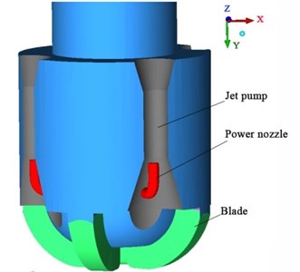
Fig. 27The vortex and jet pump combination bit
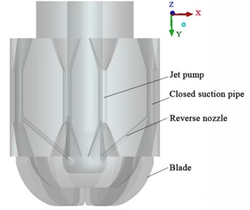
Zhu et al. also proved that the coupling of the fluid vortex and jet pump pressure drawdown method can eliminate the hinder the effect of the bit clearance on the BHDP [13]. Assuming that all fluid flows into the reverse nozzles, the axial angle of the reverse nozzle is 150°, the confining pressure is 30 MPa, the flow rate of drilling fluid is 33 L/s, and the rotation speed is 300 rpm, we further study this coupling depressurization mechanism of the vortex and jet pump combination bit using Zhu et al.’s numerical simulation method (Fig. 27). Part of the high speed drilling fluid ejected from the upward nozzle rotates with the drill bit and creates a high speed swirl, which realizes the negative pressure; the rest of the fluid still flows through the throat of the jet pump and generate the negative pressure due to venturi effect. The bottom-hole flow field of bits with different kinds of structures and distances between throat axis and bit axis is calculated when the bit clearance is 9 mm.
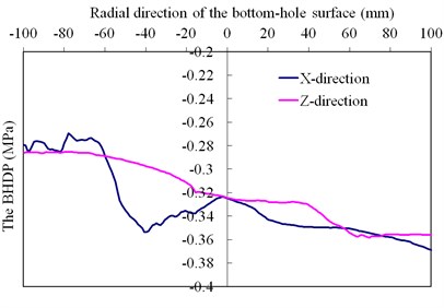
Fig. 28The BHDP along the radial direction of the combination bit
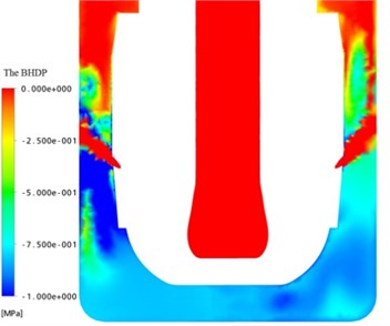
a) Vertical section with 106 mm distance
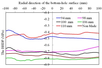
b) Different distances
The BHDP of the combination bit with different distances is about –0.4 to –0.88 MPa that is 3-4 times of the jet pump bit (Fig. 28). The pressure drawdown effects of the vortex and jet pump combination bit varies with the distance between the axis of the throat and the drill axial. The optimal distance is 106 mm for the simulation situations of this paper. During the design of other different-size bits, this optimal distance is needed to further optimize.
Fig. 29The BHDP of the combination bit with Ø12 mm closed suction pipes
a) Combination bit with closed suction pipe
b) The BHDP of radial direction
Fig. 30The BHDP of the jet pump bit with power nozzles
a) Jet pump bit with power nozzles
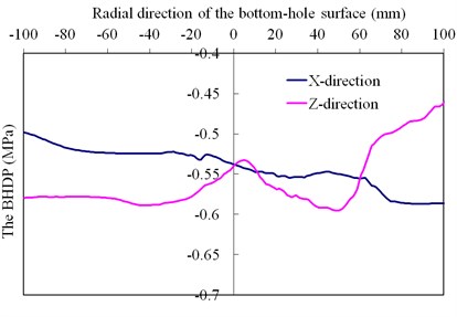
b) The BHDP of radial direction
Fig. 31The BHDP of the combination bit with power nozzles
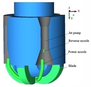
a) Combination bit with power nozzles
b) The BHDP of radial direction
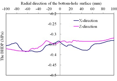
When the distance is 98 mm, the suction pipe is a Ø12 mm closed hole, and the inlet and outlet of the two ends of the suction pipe are open, the BHDP is about –0.31 to –0.39 MPa (Fig. 29). When the jet pump bit is driven by a power nozzle and the distance is 98 mm, the BHDP is about –0.45 to –0.59 MPa (Fig. 30). When the combination bit is driven by a power nozzle and the distance is 98 mm, the BHDP is about –0.26 to –0.38 MPa (Fig. 31). The depressurization capacity of jet pump bit with power nozzles is than the combination bit with closed suction pipe and the combination bit with power nozzles. The combination bit with closed suction pipe restricts the moving of drilling cuttings, and the suction pipe is more likely to be blocked. So, it is not usable. The power nozzles are harmful for the bottom-hole cuttings removing and difficult to manufacture. The combination bit with 106 mm distance is preferable.
5. Conclusion
The lower ROP in deep and ultra-deep wells has always been a major problem in the drilling industry. The BHDP is one of the main reasons that restrict the ROP. Reducing the BHDP near the drill bit while keeping the wellbore pressure to prevent wellbore instability, is an economic and safe way to increase the ROP. Three methods are tried to achieve this target (Appendix Table A1).
The casing fixing wellbore UBD jet pump does not rotate with drill string, but it needs an inner casing as a power fluid injection channel to actuate the jet pump; wellbore UBD tools have a good antihypertensive effect by reducing bottom-hole pressure about 2 MPa, which is over 10 times than that of joint and nozzle. The vertex joint only produces depressurization near the reverse nozzle and a little in the bottom-hole. The depressurization value of the reverse nozzle and jet pump bit is about 0.1 to 0.3 MPa. Because of the bit clearance, the jet pump bit does not fully play the antihypertensive effect of jet pump. The JHPDT is still in the design stage and has fewer field applications. The development of the vertex tools is faster than that of the JHPDT and the ECDRT turns out to be with good antihypertensive effect. The hydraulic pressure drawdown tools need to be further studied and tested to achieve the optimal and fast drilling, decrease the drilling time and save money.
References
-
Gao D., Zheng D. Study of a mechanism for well deviation in air drilling and its control. Petroleum Science and Technology, Vol. 29, Issue 4, 2011, p. 358-365.
-
Zeng S. Y., Wu L. S., Gao B. H. Studies of balanced drilling and well-control technique in Sichuan region. Nature Gas Industry, Vol. 6, Issue 2, 1986, p. 49-61, (in Chinese).
-
Zhu H. Y., Deng J. G., Huang K. W., Zhang C., Zhao J. Y., Du X. D. Rock mechanics characters and PDC bit optimization of glutenite formation in Pearl River Mouth Basin oilfields. Scientia Iranica, Vol. 20, Issue 4, 2013, p. 1133-1144.
-
EIA, Number of Producing Gas Wells. http://www.eia.gov/dnav/ng/ng_prod_wells_s1_a.htm, 2014.
-
Kollé J. J., Marvin M. M. Suction Pulse Drilling System. Tempress Technologies Inc., Kent, Washington, 1999.
-
Xu H., Nie C., Wu H. Bottomhole differential pressure decreasing nipple improves drilling speed dramatically. Petroleum Drilling Techniques, Vol. 26, Issue 1, 1998, (in Chinese).
-
Bern P. A., Armagost W. K., Bansanl R. K. Managed pressure drilling with the ecd reduction tool. SPE Annual Technical Conference and Exhibition, Houston, 2004.
-
Hosie D., Bansa R. K., Moves P. B. Apparatus and method to reduce fluid pressure in a wellbore. US6837313, Jan. 4, 2005.
-
Zhu H. Y., Deng J. G., Zhao J. Y. Vortex methods reducing the bottom-hole differential pressure. Journal of Mines, Metals & Fuels, Vol. 60, Issue 5, 2012, p. 81-90.
-
Yang Y., Wu Z., Shen Z., Wang R. Modulation mechanism of low-pressure pulse jet and modulator working simulation. Journal of the University of Petroleum, Edition of natural science, Vol. 27, Issue 3, 2003, p. 40-42, (in Chinese).
-
Wang Z. Theory and method of negative pulse drilling technology. Oil Drilling & Production Technology, Vol. 27, Issue 6, 2005, (in Chinese).
-
Wang X., Li G., Kang Y., Shi H., Huang Z., Xie Y. Improvement of penetration rate with hydraulic pulsating-cavitation jet compound drilling technology. Petrolei Sinica, Vol. 30, Issue 1, 2009, p. 117-120, (in Chinese).
-
Zhu H., Deng J., He Y., Li B., Xie Y., Huang K., Zhao J. Reducing bottom-hole differential pressure by hydraulic jet. Journal of China University of Petroleum, Vol. 37, Issue 2, 2013, p. 50-56, (in Chinese).
-
Du J. Theory and experiment study of well bottom vortex machine. Southwest Petroleum Institute, 2005, (in Chinese).
-
Yang Y. Y., Niu S. C., Xu X. Q. Experimental study of combined-jet PDC bit. Petroleum Drilling Techniques, Vol. 40, Issue 05, 2012, p. 100-105, (in Chinese).
-
Hughes W. J., Renfro J. J. Down hole drilling assembly with concentric casing actuated jet pump. US6899188, May. 31, 2005.
-
Hughes W. J., Renfro J. J. Down hole drilling assembly with independent jet pump. US6877571, Apr. 12, 2005.
-
Hughes W. J., Renfro J. J. Down hole drilling assembly with independent jet pump. US2003/0042048, Mar. 6, 2003.
-
Hosie D., Bansal R. K., Moyes P. B. Apparatus and method to reduce fluid pressure in a wellbore. US2007/0068705, Mar. 29, 2007.
-
Hosie D., Bansa R. K., Moves P. B. Apparatus and method to reduce fluid pressure in a wellbore. US7395877, Jul. 8, 2008.
-
de Recherche Sur Les Techniques D’Exploitation Du Pétrol ARTEP Unique tool speeds diamond bit drilling. World Oil, Vol. 187, Issue 5, 1978, p. 74.
-
Mueller M. D., Jacobson W. O. Underbalance jet pump drilling method. US5355967, Oct. 18, 1994.
-
Lott W. G. Jet pump drilling apparatus and method. US5775443, Jul. 7, 1998.
-
Sun W. Mechanism Study on the Bottomhole Pressure Reduction by Drilling Fluid Shunt on Bit. China University of Petroleum, Beijing, 2010, (in Chinese).
-
Conn A. F., Radtke R. P. Cavitating bit jets promise faster drilling for deep hole operations. Oil & Gas Journal, Vol. 75, Issue 10, 1977, p. 129-146.
-
Kolle J. J. HydropulseTM Drilling. Tempress Technologies, Inc., Kent, Washington, 2004.
-
Wang M., Wang Z., Li Z., Yang Y. Development and application of a hydraulic-pulse drilling tool. China Petroleum Machinery, Vol. 34, Issue 5, 2006, p. 27-28, (in Chinese).
-
Li G., Shi H., Niu J., Huang Z., Tian S., Song X. Hydraulic pulsed cavitating jet assisted deep drilling: an approach to improve rate of penetration. The CPS/SPE Inernational Oil & Gas Conference and Exhibition in China, Beijing, China, 2010.
-
Walter Flow pulsing method and apparatus for the increase of the rate of drilling. US6053261, Apr. 25, 2000.
-
Zhu H. Y., Liu Q. Y., Xiao X. H., Jing J. J. A 3D FEM methodology for the full-scale air hammer bit, teeth and rock contact analysis. Advanced Materials Research, Vol. 156-157, p. 1425-1429.
-
Zhu H. Y., Deng J. G., Xie Y. H., Huang K. W., Zhao J. Y., Yu B. H. Rock mechanics characteristic of complex formation and faster drilling techniques in Western South China Sea oilfields. Ocean Engineering, Vol. 39, Issue 44, 2012, p. 33-45.
-
Kollé J. J. The effects of pressure and rotary speed on the drag bit drilling strength of deep formations. Proceedings of the 71st SPE Annual Technical Conference and Exhibition, Denver, Richardson, Texas, 1996.
-
Detournay E., Atkinson C. Influence of pore pressure on the drilling response of PDC bits. The 32nd U.S. Symposium on Rock Mechanics (USRMS), Norman, Oklahoma, 1991.
-
Zhu H. Y., Liu Q. Y., Xiao X. H., Jing J. J., He C. A 3D FEM methodology for air hammer bit design. Advanced Materials Research, Vol. 156-157, p. 1435-1439.
-
Vidrine D. J., Benit E. J. Field verification of the effect of differential pressure on drilling rate. Journal of Petroleum Technology, Vol. 20, Issue 7, 1968, p. 696.
-
Cunningham R. A. An empirical approach for relating drilling parameters. Journal of Petroleum Technology, Vol. 30, Issue 7, 1978, p. 987-991.
-
Aswad Z. A. R. Optimization Techniques for a multi-Dimensional Drilling model. The University of Oklahoma, Oklahoma, 1980.
-
Warren T. M. Penetration rate performance of roller cone bits. SPE Drilling Engineering, Vol. 2, Issue 1, 1987, p. 9-18.
-
Winters W. J., Warren T. M., Onyia E. C. Roller bit model with rock ductility and cone offset. SPE Annual Technical Conference and Exhibition, Dallas, Texas, 1987.
-
Bourgoyne A. T., Young F. S. A multiple regression approach to optimal drilling and abnormal pressure detection. SPE-AIME Sixth Conference on Drilling and Rock Mechanics, Austin, Texas, 1974.
-
Hareland G., Hoberock L. L. Use of drilling parameters to predict in-situ stress bounds. SPE/IADC Drilling Conference, Amsterdam, Netherlands, 1993.
-
Rampersad P. R., Hareland G., Boonyapaluk P. Drilling optimization using drilling data and available technology. The 3rd Latin American/Caribbean Petroleum Engineering Conference, Buenos Aires, Argentina, 1994.
-
Rastegar M., Hareland G., Nygaard R., Bashari A. Optimization of multiple bit runs based on rop models and cost equation: a new methodology applied for one of the Persian Gulf carbonate fields. IADC/SPE Asia Pacific Drilling Technology Conference and Exhibition, Jakarta, Indonesia, 2008.
-
Bern P. A., Hosie D., Bansal R. K., Eng. D. S. R., Lee B. A new downhole tool for ECD reduction. The SPE/IADC Drilling Conference, Amsterdam, The Netherlands, 2003.
-
Bansal R. K., Brunnert D., Todd R., Bern P. A., Baker R. V. Demonstrating managed-pressure drilling with the ECD reduction Tool. The SPE/IADC Drilling Conference, Amsterdam, The Netherlands, 2007.
-
Reed Apparatus for reducing hydro-static pressure at the drill bit. US4744426, May. 17, 1988.
-
Liaohe Petroleum Exploration Department Headquarters Introducing a modified vortex bit. Petroleum Exploration and Development, Vol. 1, Issue 4, 1979, p. 66-68, (in Chinese).
-
Du X. A new bit. CN2332806Y, Aug. 11, 1999, (in Chinese).
-
Lamin S. B., Graham C. Reverse nozzle drill bit. US20100147594, Jun. 17, 2010.
-
Hannegan D., Divine R. Underbalanced drilling-perceptions and realities of today’s technology in offshore applications. The IASC/SPE Drilling Conference, Dallas, Texas, 2002.
-
Hariharan P. R., Judge B. ECD management tool offers potential for reducing drilling problems and costs. The Offshore Technology Conference, Houston, Texas, U.S.A., 2004.
-
Shimizu Y., Nakamura S., Kuzuhara S., Kurata S. Studies of the configuration and performance of annular type jet pumps. Journal of Fluids Engineering, Vol. 109, Issue 3, 1987, p. 205-212.
-
Grupping A. W., Coppes J. L. R., Groot J. G. Fundamentals of oil well jet pumping. SPE Production Engineering, Vol. 3, Issue 1, 1988, p. 9-14.
-
Suryanarayana P. V., Hasan A. K., Hughes W. J. Technical feasibility and applicability of a concentric jet pump in underbalanced drilling. The SPE/IADC Underbalanced Technology Conference and Exhibition, Houston, Texas, U.S.A, 2004.
-
Hughes W. J. Method and apparatus for inducing under balanced drilling conditions using an injection tool attached to a concentric string of casing. US6769498, Aug. 3, 2004.
-
Hassen B. Underbalance drilling tool and method. WO 014649, February 21, 2002.
-
Hassen B. Underbalanced drilling tool and method. Outil de forage en sous-pression, et methode connexe. CA 2315969, July 15, 2008.
-
Association De Recherche Sur Les Techniques D Exploitation Du Petrol Unique tool speeds diamond bit drilling. World Oil, Vol. 187, Issue 5, 1978, p. 74.
-
Hooper D. W. Packer weighted and pressure differential method and apparatus for big hole drilling. US4534426, Aug. 13, 1985.
-
Hooper D. W. Annulus bypass peripheral nozzle jet pump pressure ential drilling tool and method for well drilling. US4630691, Dec. 23, 1986.
-
Zheng F., Yu S., Li G., Luo H., Huang Z. Experimetal study of jet hydralic pressure drawdown. China Petroleum Machinery, Vol. 36, Issue 7, 2008, p. 4-6, 22, (in Chinese).
-
Sarita S., Yu M., Stefan M., Nicholas E. T. The effect of tool joints on ECD while drilling. The SPE Production and Operations Symposium, Oklahoma, U.S.A., 2007.
-
Majed E., Arild S. The hydraulic effect of tool-joint on annular pressure loss. SPE Production and Operations Symposium, Oklahoma, USA, 2011.
About this article

This work was supported by the SWPU Science and Technology Fund (No. 2013XJZ003), the Research Foundation of Sichuan Province under Grant No. 2014HH0004 and 14ZA0036, and the National Natural Science Foundation of China (No. 51134004 and 51374178). This work was also supported by the National Basic Research Program of China (973 Program, No. 2014CB239205).
