Abstract
The AC permanent-magnet synchronous motor with characteristics of high efficiency, high stability, long using life and simple maintenance is one of the most important developing directions in the motor field. The research on electromagnetic vibration is foundations of designing the low noising AC permanent-magnet synchronous motor. In this paper, starting from the structure of AC permanent-magnet synchronous motor, the magnetic flux density, radial electromagnetic force and vibration’s theoretical model of the three-phase AC permanent-magnet synchronous motor were deduced. Influencing factors of the electromagnetic vibration of permanent-magnet synchronous motor were analyzed from the theoretical point of view. The main frequency of electromagnetic vibration was put forward. To analyze the distribution of the electromagnetic field accurately, the three-phase AC permanent-magnet synchronous motor with 4 poles and 24 slots was simulated by numerical simulation of magnetic field, obtaining the radial flux density. By theoretical modeling and the numerical simulation of the magnetic field, the simulation results showed that when slots of the permanent-magnet synchronous motor was close to 2 times, 4 times, 6 times or 8 times of motor poles, the motor generated vibration frequency which is 2 times, 4 times or 6 times as the fundamental frequency.
1. Introduction
The AC permanent-magnet synchronous motor with simple structure, small volume, light weight, high power density, high efficiency, excellent low-speed performance, fast response, wide speed range and easy or free maintenance is of great development prospects [1, 2]. The noise index is the key factor for the normal operation of motor, and the noise comes from the vibration [3, 4], the modeling and analysis of the vibration characteristics of AC permanent-magnet synchronous motor are significant to the design.
The vibration of permanent-magnet synchronous motor can be divided into three categories [5]. The first is electromagnetic vibration, which is generated from the deformation and vibration of stator caused by the electromagnetic force. The second is mechanical vibration, which is caused by the imbalance of bearings and rotors. The third originates in the aerodynamic vibration. Since AC permanent-magnet synchronous motor has no brush and advances in high efficiency and motors with small and medium motor have no fan, noise caused by mechanical vibration and air flow is less than that caused by electromagnetic vibration. In reference [6], for medium and small motors at a low speed, the proportion of noise from the three kinds of vibrations was given. It showed that noise and vibration of medium and small motor with low speeds, noise was mainly caused by the electromagnetic vibration. Therefore, the electromagnetic vibration caused by electromagnetic force was mainly analyzed and researched in this paper.
Many scholars have done a lot of research on the electromagnetic vibration with mainly analytical method and finite element method. The analytical method has clear functions and is easy to analyze the influence of parameters to vibration and to study the law of vibration. However, it can only calculate the motor vibration accurately in connection with simple structure or under certain special circumstances. With wide scope of application, the finite element method is able to solve complex motor vibration problems. But the results are approximate solutions and lack theoretical foundation. The cause of the vibration cannot be researched in depth. In view of the characteristics of the analytical method and the finite element method, when analyzing electromagnetic vibration, we should use the analytical method as far as possible. For example, a series of references of Professor Zhu [7-11] and reference [12-14] calculated the electromagnetic force and electromagnetic vibration by analytical method. In this paper, since it is difficult to accurately solve the electromagnetic field distribution of the permanent-magnet synchronous motor and there are accurate analytical models of the electromagnetic field, electromagnetic force and motor vibration, the distribution of electromagnetic field of the motor was simulated numerically by the finite element method. Then the electromagnetic force was calculated based on the simulation results and Maxwell equations of the electromagnetic field. The motor vibration was calculated by the electromagnetic force. Factors influencing the electromagnetic vibration were analyzed, which laid the foundation for the further performance prediction and design of the noise of the permanent-magnet synchronous motor.
2. The AC permanent-magnet synchronous motor
The structure of AC permanent-magnet synchronous motor is shown in Fig. 1. Coils are winded in the stator slots. Permanent magnets are mounted on rotors. When inletting the alternating current, coil windings generate control fields, which interact with magnetic fields generated by permanent magnets on rotors and produce torque. Then rotors generate synchronous motion. The rotational speed increases with the increase of the current frequency of coil windings.
Fig. 1The structure of the three-phase AC permanent-magnet synchronous motor
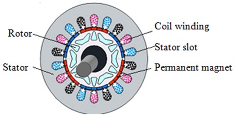
The electromagnetic force between coil windings and permanent magnets on rotors can be decomposed as the tangential and radial force. The tangential force generates torques which makes rotors rotate. The radial force causes the deformation vibration of stators and rotors. Studies showed that the vibration of stators caused by the radial force was the main source of the noise [15, 16].
3. The electromagnetic model of motor
3.1. The magnetic field model of the air gap of permanent-magnet synchronous motor
According to the basic principle of the magnetic circuit in the electromagnetic field, the permeability of the motor core is much larger than that of the air. The reluctance of the core is so small and generally negligible. Therefore, magnetic potentials of permanent magnets on rotors and armatures on stators basically land on the air gap. The magnetic potential of the air gap composes of fundamental magnetic potential, harmonic magnetic potential of stators and harmonic magnetic potential of rotors. The magnetic potential of the air gap is:
where is the current frequency of the fundamental wave of stator; is the number of the harmonic wave of stator and takes the value of ; is the number of the harmonic wave of rotor and takes the value of ; takes the value of 1, 2, 3, 4,…; is the number of pole-pairs; is the rotation angle.
The gap flux density is expressed as [17]:
where is the magnetic permeability of the air gap. Just considering the average components and first-order tooth harmonic components, the magnetic potential of the air gap can be approximated by:
where is the average component of the magnetic permeability the air gap; is the amplitude of first-order tooth harmonic components; is the number of stator slots.
With simultaneous Eq. (1)-Eq. (3), gap flux density can be deduced:
Because and discarding product terms with small amplitude, Eq. (4) can be simplified to:
This is the air gap flux density model of the permanent-magnet synchronous motor. The air gap field of the permanent-magnet synchronous motor can be obtained by it.
3.2. The theoretical foundation of the numerical simulation of magnetic field
The numerical simulation of magnetic field is based on Maxwell equations, namely [18]:
where is the intensity of the electric field; is the intensity of magnetization; the intensity of the magnetic field; is the intensity of the current; is the density of the charge.
Because mediums meet:
where is the magnetic permeability; is the conductivity; is the dielectric constant.
Taking Eq. (10)-Eq. (12) into Eq. (6)-Eq. (9), the electromagnetic field with sinusoidal characteristics meets:
Because , there is magnetic potential to make:
So:
Because:
Combining Eq. (8), Eq. (11) and Eq. (12) show that:
Taking Eq. (6) into Eq. (18), the above equation can be written as:
Combine Eq. (19) with Eq. (17) to get:
Remove of Eq. (20) to obtain an equation about :
Eq. (16), Eq. (20) and Eq. (21) constitute the theoretical foundation of the numerical simulation of magnetic field. In the numerical simulation, in addition to theoretical formulas, boundary conditions are also needed. Boundary conditions of numerical simulation of the magnetic field can be divided into three categories. The first is to directly give the value of an unknown function on the boundary. The second is to give the directional derivative along the normal outside the boundary of an unknown function. The third is to give some linear combinations along the outer normal derivative of an unknown function.
3.3. The model of the numerical simulation of magnetic field
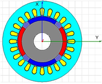
The structural parameters of the motor: the inner diameter and outer diameter of the stator are respectively 16 mm and 23.3 mm; 4 poles and 24 stator slots. According to Fig. 1, the model of the numerical simulation of magnetic field can be drawn as shown in Fig. 2.
Fig. 2The numerical simulation of the three-phase AC permanent-magnet synchronous motor
4. The model of electromagnetic vibration
4.1. The model of electromagnetic force
The main reason for the electromagnetic vibration is the influence of the radial electromagnetic force on stators. Knowing from the Maxwell stress equations, the instantaneous radial electromagnetic force on the inner surface unit area of the stator teeth [19]:
Taking Eq. (5) into Eq. (22). After the prosthaphaeresis of the vibration of stators and ignoring items with high stress wave order, the instantaneous radial electromagnetic force per unit area can be obtained:
The radial force of stators:
where is the inner diameter of stator cores; is the length of stator cores.
4.2. Vibration model
The dynamic model of mechanical vibration can be equivalent to a mass – spring – damper system, so as to meet the force balance equation:
where , and are namely mass matrix of the mechanical system, damping matrix and stiffness matrix; and are displacement and force of nodes.
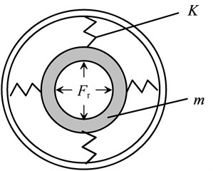
To simplify the analysis, the stator is simplified into a cylindrical shell with two end covers. Two ends are free. The equivalent simplified vibration model is shown in Fig. 3.
Fig. 3The equivalent simplified vibration model of the stator
Considering only the radial direction of the stator vibration, when the order of the electromagnetic force equals that of the motor, the amplitude of radial vibration displacement of the stator with order m produced by electromagnetic force is:
where is the equivalent mass of cylindrical shell; is m-order natural angular frequency; is the angular frequency of -order electromagnetic force; is the amplitude of radial electromagnetic force from Eq. (24). is the modal damping ratio, which is difficult to be analyzed theoretically and got by experimental methods. Its value is influenced by the frequency and winding layers. Empirical formula is:
where is the natural frequency of the cylindrical shell. Formula of its value is:
where is the Poisson’s ratio of the stator core. The value of is:
where . When , . is the dimensionless thickness parameter:
where is the thickness of the stator core.
5. Simulation analysis
5.1. The analysis of electromagnetic vibration frequency
The form of Eq. (23) shows that the radial electromagnetic force is a kind of wave. Motor vibration amplitude is inversely related to the order of stress wave. Know from the five items in braces of Eq. (23).
The order of stress wave of the first one is 2, and the motor vibration frequency is 2 times as the fundamental wave.
The order of stress wave of the second one is . When the slot number of the statoris close to the pole number of the motor 2, that is, , the motor will produce vibration frequency which is 2 times as the fundamental frequency.
The order of stress wave of the third one is . When the harmonic wave number of the stator is equal to that of the rotor, vibration with the frequency of will generate. When take when take For the three-phase synchronous motor, the value formula of harmonic wave numbers of the stator and the rotor shows that when the harmonic wave number is low, if equals and the value is 5 or 7, the motor will produce vibration frequency which is 6 times as the fundamental frequency.
The order of stress wave of the fourth one is . When , the coefficient before the time is 0 and there is no vibration. When , the coefficient before the time is 2. When the order number of stress wave is close to 0, the motor will produce vibration frequency is 2 times as the fundamental frequency. Therefore, for the three-phase synchronous motor, the vibration when is 5 or 7 is: when 5, there is no vibration; when 7, the motor will produce vibration frequency which is 2 times as the fundamental frequency and the number of stator slots .
The order of stress wave of the fifth one is . When , the motor will produce electromagnetic vibration with the frequency of . For the three-phase synchronous motor, low harmonic wave will still be analyzed. Take the harmonic wave number of the rotor as 3 or 5. When 4 or 6, the motor will produce vibration frequency which is 4 or 6 times as the fundamental frequency.
The foregoing analysis shows that the electromagnetic vibration frequency of three-phase permanent-magnet synchronous motor is mainly 2 or 6 times as the fundamental frequency. When the slots number of the stator is close to 4 and 6, the electromagnetic vibration also includes vibration frequency which is 4 or 6 times as the fundamental frequency.
5.2. The simulation analysis of the electromagnetic force
Eq. (24) shows that the electromagnetic force wave is a function influenced by mechanical angle and time. Therefore, the magnetic flux density and electromagnetic force wave were simulated according to spatial location and time.
Parameters of the simulation are shown in Table 3. Take the intermediate mechanical angle of the inner surface of the stator as 30°. Substitute it into Eq. (5). For the three-phase permanent-magnet synchronous motor, when neglecting items with high harmonic wave and the stator is 5 or 7 and rotor is 3, 5 and 7, the curve of magnetic flux density is shown in Fig. 4.
Simulation parameters of Eq. (24) is same with Eq. (5). When the harmonic wave number of the stator takes 5 and 7, the harmonic wave number of the rotor takes 3, 5 and 7 and the mechanical angle is 30°, the curve of stress wave is shown in Fig. 5.
Fig. 4The radial flux density changes with time at the angle of 30°
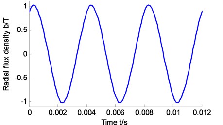
Fig. 5The radial force changes with time at the angle of 30°
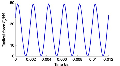
Fig. 6The radial flux density changes with the space angle
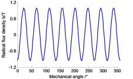
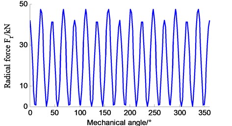
Fig. 7The radial force changes with the space angle
Parameters of the simulation are shown in Table 3. When the harmonic wave number of the stator takes 5 and 7, the harmonic wave number of the rotor takes 3, 5 and 7 and the permanent-magnet synchronous motor rotates at a certain moment (set ), the curve of radial flux density changing with the mechanical angle is shown in Fig. 6.
Simulation parameters are as above. When the permanent-magnet synchronous motor rotates at a certain moment (set ), the curve of radial electromagnetic force changing with the mechanical angle is shown in Fig. 7.
From Fig. 4 to Fig. 6, the radial air gap flux density and the radial electromagnetic force wave are periodic from space and time. And the frequency of the radial electromagnetic force wave is 2 times of that of the radial air gap flux density.
5.3. The numerical simulation of the electromagnetic field
According to structure parameters in Table 1 and the electromagnetic field simulation of the three-phase AC permanent-magnet synchronous motor in Fig. 2, simulation results can be shown in Fig. 8 and Fig. 9.
Table 1The radial vibration mode of the stator
Modal number | 0 | 1 | 2 | 3 | 4 | 5 | 6 | 7 |
Frequency (Hz) | 7572 | 116 | 464 | 1313 | 2517 | 4070 | 5971 | 8218 |
Fig. 8The radial force changes with the space angle
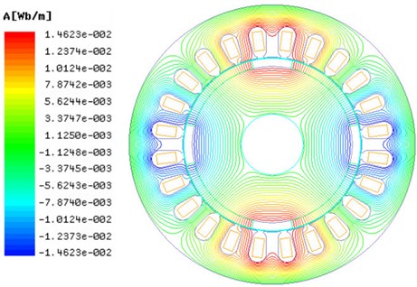
Fig. 9The simulation results of magnetic flux density of the three-phase AC permanent-magnet synchronous motor
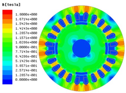
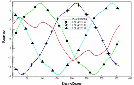
Knowing from Fig. 8 and Fig. 9, numerical simulation results of the electrical angle and radial air gap flux density are shown in Fig. 10. Fig. 11 to Fig. 13 are simulation curves of electrical parameters of the three-phase AC permanent-magnet synchronous motor. Fig. 11 shows that the maximum no-load is close to 175 V, the winding current is close to 4 A. In the rated load, electrical angle and phase voltage curve are sinusoidal.
Fig. 10The simulation results of magnetic flux density of the three-phase AC permanent-magnet synchronous motor
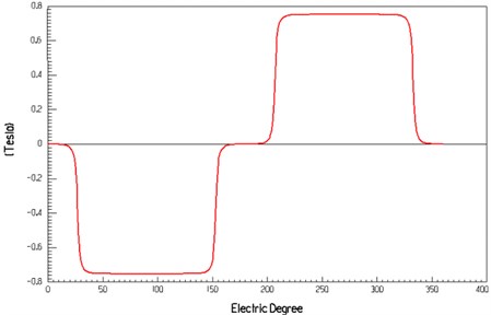
Fig. 11The relationship between the electrical angle and winding back EMF
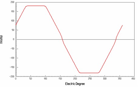
Fig. 12The relationship between the electrical angle and the winding current
5.4. The calculation of electromagnetic vibration
By the motor’s structural parameters of Eq. (26) to Eq. (30) and Table 3, the relationship between the radial electromagnetic force and vibration displacement of the stator of the three-phase AC permanent-magnet synchronous motor in different stress wave and frequency is shown in Table 2.
Fig. 13The relationship between the electrical angle and the phase voltage with the rated load
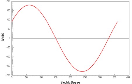
Table 2The vibration calculation of the permanent-magnet synchronous motor
The number of stress wave | Frequency / Hz | The amplitude of radial force / N | Vibration displacement / μm |
2 | 500 | 46600.00 | 3.16 |
4 | 1000 | 3728.0 | 0.253 |
4 | 1500 | 1752.4 | 0.119 |
2 | 2000 | 753.4 | 0.051 |
2 | 2500 | 63.4 | 0.004 |
As can be seen from Table 2, the vibration displacement of the 500 Hz electromagnetic force can be 3.16 μm. As the main component of the electromagnetic vibration, the vibration frequency is 2 times as the fundamental frequency.
Table 3Motor parameters
Name | Symbol | Value |
The number of slots | 24 | |
The quality of the stator core | 8.58 kg | |
The inner diameter of the stator | 160 mm | |
The outer diameter of the stator | 233 mm | |
The length of the stator core | 197.5 mm | |
The width of the stator slot | 5.87 mm | |
The length of the stator slot | 3 mm | |
The thickness of the stator | 8.42 mm | |
Modulus of elasticity | 200 GPa | |
The Poisson’s ratio of the stator | 0.3 |
6. Conclusions
From research on the air gap magnetic field, electromagnetic force and vibration, we can obtain the following conclusions:
1) The electromagnetic vibration frequency of three-phase AC permanent-magnet synchronous motor is mainly 2 or 6 times of the fundamental frequency. When the slots number of the statoris close to 4 and 6, the frequency of violent vibration also includes vibration which is 4 or 6 times as the fundamental frequency.
2) The electromagnetic vibration of the three-phase permanent-magnet synchronous motor is mainly from the radial vibration of the stator. The radial air gap flux density and the radial electromagnetic force wave are periodic from space and time. And the frequency of the radial electromagnetic force wave is 2 times of frequency of the radial air gap flux density.
3) The simulation and analysis of the permanent-magnet synchronous motor with 4 poles and 24 slots show that when the frequency of the radial electromagnetic force wave is 2 times as the fundamental frequency, the electromagnetic vibration is severe.
References
-
Li J. W. Research on electromagnetic vibration and noise for low-power permanent magnet synchronous motor. Harbin Institute of Technology, Harbin.
-
Yang H. D. Electromagnetic vibration analysis of permanent magnet synchronous motor. Zhejiang University, Hangzhou, 2011.
-
Zhang L., Weng X. H. Radial electromagnetic vibration model characteristics of PMSMs for electic vehicles. Electric Machines and Control, Vol. 16, Issue 5, 2012, p. 33-39.
-
Chen Y. X., Chu Z. Q., Ying S. C. Motor noise of analysis and control manual. Zhejiang University Press, 1987.
-
Li X. H., Huang S. R., Xin L. Z. Calculation and analysis of vehicle vibration and noise of permanent magnet synchronous motor applied in electric vehicle. Electric Machines and Control, Vol. 17, Issue 8, 2013, p. 37-42.
-
Lisner R. E., Timar P. L. A new approach to electric motor acoustic noise standards and test procedures. IEEE Transactions on Energy Conversion, Vol. 14, Issue 3, 1999, p. 692-697.
-
Cui S. L. Calculation and analysis of electromagnetic vibration and noise for small and medium-sized induction motor. Harbin University of Science and Technology, Harbin, 2011.
-
Zhu Z. Q., Howe D. Instantaneous magnetic field distribution in brushless permanent magnet dc motors. Part I: Open-circuit field. IEEE Transactions on Magnetics, Vol. 29, Issue 1, 1993, p. 124-135.
-
Zhu Z. Q., Howe D. Instantaneous magnetic field distribution in brushless permanent magnet de motors. Part II: armature-reaction field. IEEE Transactions on Magnetics, Vol. 29, Issue 1, 1993, p. 136-142.
-
Zhu Z. Q., Howe D. Instantaneous magnetic field distribution in brushless permanent magnet de motors. Part III: Effect ofstator slotting. IEEE Transactions on Magnetics, Vol. 29, Issue 1, 1993, p. 143-151.
-
Zhu Z. Q., Howe D. Instantaneous magnetic field distribution in permanent magnet brushless dc motors. Part IV: magnetic field on load. IEEE Transactions on Magnetics, Vol. 29, Issue 1, 1993, p. 152-158.
-
Fu J. J. Coupled magnetic-mechanic analysis of the electromagnetic vibration of a permanent magnet machine. Zhejiang University, Hangzhou, 2012.
-
Yu S. B. Research on behavior of vibration and noise in permanent magnet synchronous motor. Shenyang University of Technology, Shenyang, 2006.
-
Jacek F. Gieras, Chong Wang, Joseph Cho Lai Noise of Polyphase Electric Motors. Marcel Dekker Inc, 2005.
-
Li J. W., Cheng S. K. Research on the vibration and noise of the minitype permanent magnet synchronous motor. Science Paper Online, 2011, p. 1-6.
-
Liu J. H., Huang K. S., Chen Z. Y. Analysis of radial electromagnetic force of permanent magnet synchronous motors. Small and Special Electrical Machines, Vol. 41, Issue 5, 2013, p. 16-22.
-
Yang H. D., Chen Y. S., Deng Z. Q. Electromagnetic vibration of PM synchronous motors with different combinations of slot and pole number. Transactions of China Electrotechnical Society, Vol. 26, Issue 9), 2011, p. 24-30.
-
Zuo S. G., He L. C., Wei H. Dynamic analysis and experimental research on stator vibration of BLDC motor. Journal of Vibration and Shock, Vol. 31, Issue 10, 2012, p. 106-110.
-
Wang X. H., Li Q. F., Wang S. H., et al. Analytical calculation of air-gap magnetic field distribution and instantaneous characteristics of brushless dc motors. IEEE Transactions on Energy Conversion, Vol. 18, Issue 3, 2003, p. 424-432.
About this article

This work was supported by a grant from the innovation team training plan of Tianjin colleges (TD12-5043).
