Abstract
Take experiment research on characteristics of turbine expansion engine’s shaft supported by herringbone grooved aerodynamic journal bearing, with the emphasis on its low frequency whirl. Get bearing’s taking-off speed and low frequency vibration characteristics by comprehensively analysis methods of spectrum diagram, haft orbit and time waveform and bifurcation diagram. The result shows that the graphite made herringbone groove hydrodynamic bearing can reach 37548 r/min and half-frequency vibration happens since 13021 r/min. With the speed up, rubbing exists and the amplitude of low frequency even bigger than power frequency. The result shows that the half-frequency is the main unstable factor.
1. Introduction
Compared with liquid lubricated journal bearings, gas bearing is widely used in high-speed turbine expansion engine due to its advantages such as low friction, low heat and environmentally friendly [1]. One of hydrodynamic bearing’s outstanding features is no external high pressure supply, which greatly simplifies the complexity of bearing lubrication system [2]. Viscous gas between relative motion convergent wedges in aerodynamic bearing generates pressure film to support rotor. The characteristic of fluid-solid coupling in gas bearing-rotor system makes rotor easy to present nonlinear behaviors like whirl, oscillations and resonance, affecting the stability of rotor [6]. Therefore, taking off speed and stability become key performances in design of aerodynamic bearing. Yang Lihua does experiment research on aerodynamic compliant foil bearing’s taking off speed and capacity. Analysis is conducted through friction torque and radial displacement response spectrum [7]. Chen-Chi Wang calculates herringbone groove aerodynamic bearing-rotor system’s nonlinear dynamic behaviors. Rotor’s orbit, phase diagrams, Poincare map, energy spectrum are calculated to study rotor’s stability. The rotor shows results shows quasi-periodic and periodic dynamic response characteristics under different bearing numbers. Yang Jinfu analyzes sliding bearing-rotor’s low frequency vibration features. Shaft’s engineering stability criterion is built and coupling regulating frequency technology is put up to avoid film whirl and oscillation in order to improve rotor’s stability [9-10].
New graphite made herringbone groove hydrodynamic bearing researched in this paper has performances such as self-lubricating, high wear and impact resistance, wide temperature adaptability [11]. The paper does experiment research on shaft’s stability in high-speed turbine expansion. Amphasis is paid on grooved aerodynamic bearing’s taking-off speed and rotor’s low frequency vibration.
2. Experiment test rig and scheme
2.1. Experiment test rig
Gas bearing-rotor test lab consists of three parts which are power and pipeline control system, mechanical components and vibration signal acquisition, storage and analysis system. The test system is shown in Fig. 1.
Fig. 1Aerodynamic bearing-rotor experiment and test system
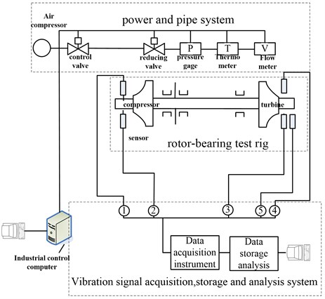
Air compressor provides air which can supply 0.1-1.3 MPa and 21-2°C’s gas as power to drive rotor. Pipe consists of regulator valve and piping filter regulator. There are pressure gauges, thermometers and flow meters to monitor gas’s state parameters. Four ZA-21 series eddy current displacement sensors are placed to measure horizontal and vertical directions of vibration displacement near the journal. In addition, a fifth sensor (eddy current displacement sensor) is used to measure rotor rotational speed. Signals from sensors are transmitted to a data logger. Then the signal is storage in computer after anti-filter amplifier for data analysis.
2.2. Structure of bearing and rotor
Herringbone grooves aerodynamic bearing and rotor is shown in Fig. 2. Bearing is radial-thrust hybrid bearing. Main parameters are lists in Table 1.
Fig. 2Structure of bearing and rotor
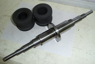
Table 1Structure parameter of bearing
Parameter | Symbol / unit | Value |
Length of bearing | / mm | 37.5 |
Diameter of bearing | / mm | 25 |
Angle of groove | / degree | 25 |
Number of groove | – | 11 |
Length of groove | / mm | 10 |
Depth of groove | / mm | 0.02 |
Length of rotor | / mm | 300 |
Mass of rotor | / g | 600 |
2.3. Experiment scheme
In order to study rotor’s vibration properties in the process of speeding up, rotor runs from 0 to maximum speed through controlling turbine’s gas flow. Vibration signals are collected and analysis is done to monitor and diagnose rotor’s stability status.
3. Experiment result and analysis
3.1. Bearing’s taking-off speed analysis
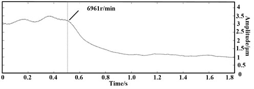
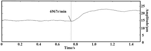
Fig. 3 is rotor’s spectrum structure diagram. We can infer that bearing’s taking-off speed is about 6961 r/min.
Before certain speed, surfaces between rotor and bearing forms dry friction. There is a large continuous low-frequency component in addition to a large half-frequency whirl component. After rotor’s taking-off, surfaces between rotor and bearing forms hydrodynamic gas film to support rotor. Spectrum diagram contains only power frequency and the other frequency components are much smaller. This phenomenon is consistent with the literature [7].
Fig. 3Spectrum diagram before and after taking-off
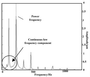
a) Before
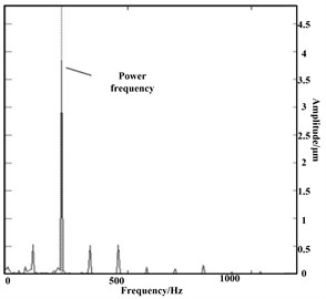
b) After
Fig. 4Time-amplitude curve
a) Before
b) After
Fig. 4 is amplitude-frequency curve in horizontal and vertical directions. In 6961 r/min, the amplitudes of the two directions change suddenly. The amplitude of the horizontal direction decreases from 3.237 μm to 1.125 μm. The vertical direction increases from 14.73 μm to 23.06 μm. For obvious presence of dynamic pressure, the rotor is floated by dynamic gas film so that amplitude jump occurs in both directions.
3.2. Low frequency vibration analysis
Fig. 5 is an amplitude-time-frequency diagram in direction of horizontal. The horizontal axis is frequency and the vertical axis is running time. Chromatogram’s brightness indicates the amplitude of vibration.
Fig. 5Spectrum structure diagram
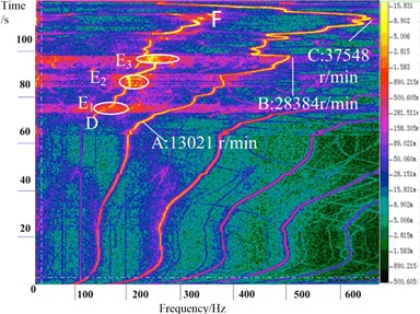
In Fig. 5, curve ABC shows power frequency vibration. Low frequency vibration occurs since 13021 r/min. When the rotor accelerates to maximum speed 37548 r/min, the low frequency whirl doesn’t disappear. Curve DF shows low frequency vibration.
Point B’s speed is 28384 r/min (473.08 Hz) corresponding to the low vibration frequency of 236.53 Hz; point C’s speed of 36687 r/min (611.54 Hz), corresponding to the the low vibration frequency of 355.77 Hz. During the whole speeding-up process, low-frequency vibration ratio ranges from 0.495 to 0.507.
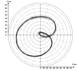
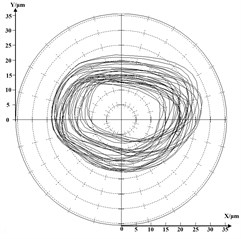
Figs. 6-7 are rotor’s orbit and frequency spectrum diagram in 10672 r/min when there is no low frequency vibration. Rotor’s orbit shows feature of periodic one and the amplitude of rotor is below 10 μm.
Fig. 6Shaft’s orbit in 10605 r/min
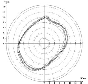
Fig. 7Shaft’s frequency spectrum diagram 10605 r/min
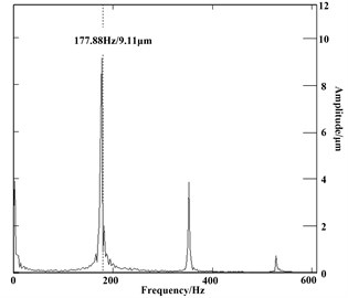
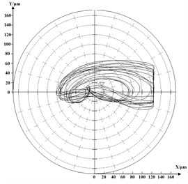
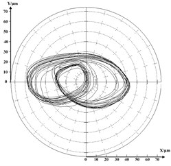
Figs. 8-9 are shaft orbit and spectrum structure diagram when rotor’s speed is 20974 r/min. Shaft orbit shows feature of periodic two. From vibrating frequency spectrum we can see that power frequency vibration’s amplitude is 9 μm and low frequency vibration’s amplitude is 33 μm. They are in the same order of magnitude and half-frequency is bigger.
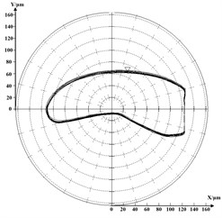
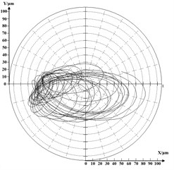
During rotor’s half-speed whirl period, the process accompanied with rubbing, as shown in Fig. 5’s E1-E3 region. The following three pictures are rotor’s vibration features when rubbing occurs. Fig. 10 is time domain waveform we can see that peak clipping exists in A, B and C ponit. Fig. 11 is shaft’s frequency spectrum diagram, there are a lot of low frequency vibration besides half frequency vibration. Fig. 12 is rotor’s orbit and it presents disorder features.
Fig. 8Shaft’s orbit in 28384 r/min
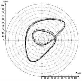
Fig. 9Shaft’s frequency spectrum diagram in 28384 r/min
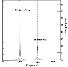
Fig. 10Time domain waveform when rubbing
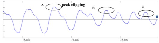
Fig. 11Shaft’s frequency spectrum diagram when rubbing
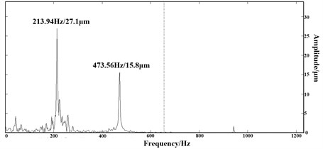
Fig. 12Shaft’s orbit diagram when rubbing
When speed reaches 13021 r/min, the rotor runs in unstable condition. Fig. 13(a)-(e) presents rotor’s unstable process before speeding down. Rotor experiences the following status: a) half frequency vibration which low frequency’s amplitude is small; b) rubbing; c) disorder; d) half frequency vibration which low frequency’s amplitude is big d) disorder e) speed down.
4. Conclusion
From experiment result, we can get the conclusion as follows:
1) New structure of pure graphite herringbone groove hydrodynamic bearings-rotor speed can reach 37548 r/min, and its taking-off speed is 696 1r/min;
2) The experiment verifies the half-speed whirl is an inherent property of the dynamic bearing and half-speed whirl frequency ratio is 0.495-0.507;
3) Rubbing exists during speed-up process. Hydrodynamic bearing’s shape is not the most optimized. For delaying or inhibiting the occurrence of half-speed whirl and rubbing, optimization groove need to be designed.
Fig. 13Rotor’s orbit diagram near the highest speed
a) 32951 r/min (110.696 s)
b) 36193 r/min (112.725 s)
c) 35983 r/min (113.515 s)
d) 37453 r/min (114.110 s)
e) 36391 r/min (1135.650 s)
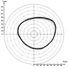
f) 29642 r/min (117.043 s)
References
-
Tougou Shinichi Design Manufacture and Application of Gas Bearing. Beijing, Aerospace Press, 1988.
-
Wang Yunfei Gas Lubricant Theory and Bearing Design. Beijing, China Machine Press, 1999.
-
Yu Lie, Heng Haipeng Compressible gas lubrication and elasticity foil air bearing technology. Beijing, Science Press, 2011.
-
Hou Yu, Xiong Lianyou, Wang Jin Design and experimental study of self acting gas bearings for cryogenic turboexpanders. Cryogenic Technology, 2002, p. 6-9.
-
Zhou Heng, Liu Yanzhu The Principle and Calculation of Aerodynamic Bearing. Beijing, National Defence Industry Press, 1982.
-
Yang Jinfu Research on fluid dynamic lubricant and stability of hydrodynamic lubrication bearing-rotor system. Doctoral dissertation of North China Electric Power University, 2006.
-
Yang Lihua, Shi Jianhua, Liu Heng The experimental study on the lift off speed and load capacity of compliant aerodynamic foil journal air bearings. Lubrication Engeering, Vol. 3, 2006, p. 15-18.
-
Cheng-Chi Wang, Her-Terng Yau, Ming-Jyi Jang Theoretical analysis of the non-linear behavior of a flexible rotor supported by herringbone grooved gas journal bearings. Tribology International, Vol. 40, 2007, p. 533-541.
-
Yang Jiufu, Yang Shengbo, Chen Ce Research on sliding bearings and rotor system stability. Journal of Aerospace Power, Vol. 23, Issue 8, 2008, p. 1420-1426.
-
Chen Ce, Yang Jiufu, Nie Chaoqun Experimental research on nonlinear dynamic characteristic of gas lubrication bearings and high speed rotors. Journal of Aerospace Power, Vol. 28, Issue 8, 2008, p. 1413-1419.
-
Liu Yuhan, Yang Jinfu, Liu Baoyu Experimental research on hydrodynamic and hybrid bearing. The 10th National Vibration Technology and Application paper, Nanjing University of Aeronautics and Astronautics, Nanjing, 2011, p. 384-388.
-
Chen Ce, Yang Jiufu, Nie Chaoqun Experimental research on hydrostatic dynamic hybrid gas lubrication bearings dynamic stability. Lubrication Engeering, Vol. 12, Issue 32, 2007, p. 30-35.
About this article

