Abstract
This paper aims to explore fault characteristics extraction method to deal with the light and severe rolling element faults based on local mean decomposition (LMD) and Fourier transform (FT). The characteristics of LMD are studied by processing multi-component frequency modulation and amplitude modulation (FM-AM) signal, which are usually used to describe the bearing fault signals. Based on the simulation analysis, the envelope spectrum method called LMD-FT is used to deal with the vibration signals of rolling balling bearing with various element faults. Moreover, the fault features extracted by LMD are compared with those obtained from conventional Hilbert transform (HT). The results demonstrate that LMD method is an effective way to identify the characteristics of rolling element defect generated at the initial stage.
1. Introduction
Ball bearing is widely used in the field of rotating machinery. But bearing fault is the most common origin of equipment failure in industry. Therefore, great attentions have been paid to the condition monitoring and fault diagnosis of bearing [1]. One of the principal tools for diagnosing bearing faults is the vibration-based analysis method because of the ease of vibration measurements. Vibration signal analysis has been widely used to extract vital diagnostic information from the vibration signals. It has been proven to be an effective method to enhance safety and reliability in manufacturing processes [2].
The vibration test signals of bearing are generally recognized as FM-AM signals. Many methods have been developed to analyze the frequency and amplitude modulation characteristics of the bearing test signals. The traditional methods include breadth-field analysis (for example Root Mean Square and Kurtosis), time-field analysis and frequency-field analysis (the fast Fourier transform and the envelope spectrum analysis). Among these methods, the envelope spectrum analysis, especially Hilbert transform (HT), is typically used to analyze the decomposition signals, diagnose the type of bearing faults, and localize the bearing faults [3]. Hilbert spectrum analysis has high resolution in signal processing and it may decompose frequency modulation components at high signal-to-noise ratio. But it is applicable to single component decomposition only. While the vibration signals tested from the bearing house are always mixed with those signals originated from the meshing gears, shafts and other components [4], therefore, the signals of bearing faults are usually made by a variety of mixed multi-component AM-FM signals. Moreover, the window effect usually appears in Hilbert analysis. For these problems, the Hilbert transform cannot meet the increasing demand of precise diagnosis for bearing faults.
With the rapid development of signal processing techniques, some researchers attempted to introduce unsteady signal processing methods, especially time-frequency analysis techniques like the short time Fourier transform (STFT) [5], wigner-ville distribution(WVD) [6], wavelet transform (WT) [7] and empirical mode decomposition (EMD)[8], etc. into analysis of bearing faults. However, each aforementioned method has its intrinsic shortage. For example, envelope spectrum analysis is suitable to process single-component rather than multi-component frequency and amplitude modulation signals, for example the vibration signals originated from operating bearing with element defects. The WT, which provides a time-frequency map of the signals, is limited by the size of the wavelet function, and moreover, the downside of the uniform resolution is uniformly poor. In addition, a significant limitation of the wavelet analysis is its non-adaptive nature [7]. Though EMD is a powerful tool to diagnose bearing faults, some drawbacks such as end effect, overshoot and undershoot are obstacles for its practical applications [9]. Recently, a new iterative composition method, called local mean decomposition (LMD), has been developed by Smith [9]. LMD provides new idea to decompose multi-component modulated signal into a set of product functions (PFs). Each product function is a one-component function with respect to time. Its end effect is declined compared with EMD, and the problems of overshoot and undershoot are solved. LMD showed the bright prospect in dealing with multi-component modulated signals [10], and has applied to diagnose bearing fault [11].
However, the application of LMD in fault diagnosis field is still a new thing. Few literature about the LMD used in the fault diagnosis of rolling element with varying degrees of failure can be found, especially when the rolling element with different defects has not been thoroughly studied.
The main work of this paper is to investigate how to diagnose the ball bearing with different rolling element defects based on LMD. Hence the LMD is employed to diagnose rolling element fault in this study, and the results are compared with the traditional method.
2. Theoretical background of LMD-FT
LMD is initially established to decompose amplitude and frequency modulated signals into a small set of product functions, each of which is the product of an envelope signal and a pure frequency modulated signal. The instantaneous amplitude is the envelope signal, and the instantaneous frequency is derived from the pure frequency modulated signal. The key of the LMD method is extracting the instantaneous frequency and instantaneous amplitude from the original signals. The LMD theory is described in the literature [9].
Various numbers of PFs may be decomposed during LMD calculation, associated with different ending criterion of iteration. Since the PFs interested in fault diagnosis are those which contain fault information, the decomposition process based on LMD is improved by reducing numbers of PFs to increase the calculation speed. The PFs induced by slight fault are generally covered by noise, therefore small energy PFs decomposed from LMD are almost unable to denote the fault information of a structure. Hence when the energy of decomposed PFs is 90 percentage of the original signal energy, the other components are not decomposed anymore in present study.
In this section, a simulation is conducted to illustrate the performance of LMD. The artificial signals are described as follows:
where:
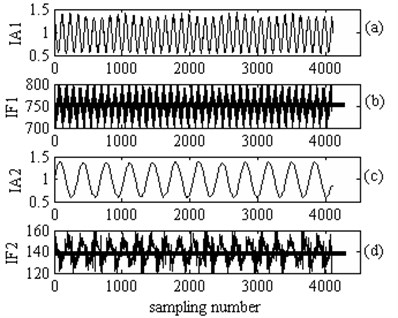
The signals consist of amplitude modulation signals and frequency modulation signals is the high-frequency component and is the low-frequency component. According to Eq. (2), it can be judged that the range of instantaneous frequency (IF) of is Hz and the range of the instantaneous amplitude (IA) is . Similarly, resulting from the analysis to the low-frequency component, it can be found that the range of the Instantaneous Frequency (IF) is Hz and the range of IA is . Two PFs can be gained from by LMD, as shown in Fig. 1.
The IF of PF1 is a periodical oscillatory signal around 750 Hz, which is in accordance with the carrier frequency of , as shown in Fig. 2(a) and (b). And the IF of PF2 is a periodical oscillatory signal around 140 Hz, which is corresponding to the carrier frequency of , as shown in Fig. 2(c) and (d).
Fig. 1The PFs obtained by LMD: a) PF1, b) PF2, c) residual component
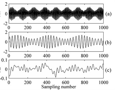
Fig. 2a) IA of PF1, b) IF of PF1, c) IA of PF2, d) IF of PF2
The analysis results show LMD is suitable to analyze the multi-component frequency and amplitude modulation signals, and all the mono-component IAs can be obtained by LMD respectively. The spectrum of IAs, similar to HT envelope spectrum, reflects the fault information. Therefore, the new envelope spectrum method derived from LMD and FT is presented to deal with the data of balling bearing.
3. Experiment and analysis
The experimental data are collected from Bearing Data Center of the Case Western Reserve University [12]. The motor bearings were seeded with faults using electro-discharge machining. Defects were ranging from 0.007 inches to 0.040 inches in diameter. The actual test conditions of the motor, as well as the bearing fault status, have been carefully documented for each experiment. Vibration data is collected using accelerometers, which are attached to the housing with magnetic bases. Digital data are collected at rate of 12,000 samples per second. Speed and motor data is collected by using the torque transducer/encoder. The bearing, named 6205-2RS JEM SKF, is a deep groove ball bearing, and its main parameters are shown in Table 1.
Table 1Main parameters of the rolling bearing
The parameter’s name | The parameter’s value |
Number of the elements | 9 |
Bearing diameter / mm | 25 |
Bearing pitch diameter / mm | 52 |
Contact angle / ° | 0 |
Based on the geometric parameters and rotating frequency, the characteristic frequency of rolling element faults is calculated to be 4.7135 times of rotary frequency.
3.1. Slight/early fault
The slight/early fault means that the defect range is very small as 0.007 inches in diameter. The motor speed is 1772 rpm, i.e. the ball defect frequency is 139.2 Hz.
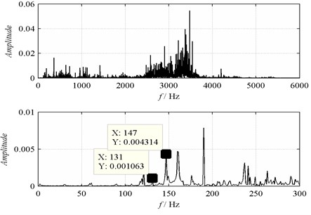
The time domain waveform of the vibration acceleration signal is shown in Fig. 3 and Fig. 4 illustrates its spectrum. A possible resonance area can be seen from the spectrum of the measured signal. It can be observed that the fault features is so weak that it is drowned by the background signals relevant to the rotary speed of the rotor and other noise. Spectral line near 139 Hz can’t be observed clearly. Therefore, it cannot be concluded that ball is in fault.
Fig. 3The time-domain waveform
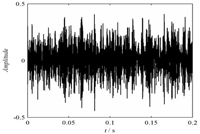
Fig. 4The amplitude spectrum
The signals are transformed by Hilbert transform to obtain frequency demodulated spectrum, as shown in Fig. 5. There are so many spectral lines that it is difficult to judge only element fault. Four PFs components and the IAs of each PF can be obtained synchronously by LMD, and spectrum analysis is applied to the envelope of four PF components to extract the crucial frequency and the result is shown in Fig. 6. It is clearly seen that a spectral line at 134.5 Hz, which is near to the ball defect frequency (139.2 Hz), and a double frequency is also found. Therefore, it is coincidental to the ball fault type.
Fig. 5Frequency demodulated spectrum obtained by Hilbert transform
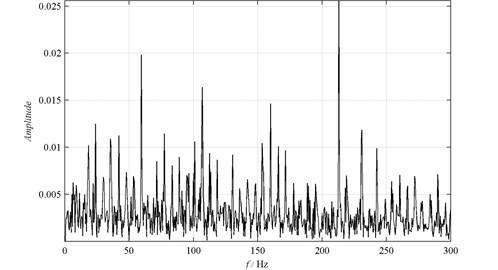
Fig. 6Spectrum of the IAs: a) IA1; b) IA2; c) IA3; d) IA4
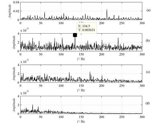
Fig. 7Frequency spectrum: a) FFT; b) HT
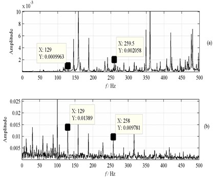
Fig. 8Spectrum of IA: a) a1; b) a2; c) a3, d) a4
3.2. Serious fault
The serious fault means that the defect range is long as 0.021 inches in diameter. The motor speed is 1750 rpm, i.e. the ball defect frequency is 135.9 Hz.
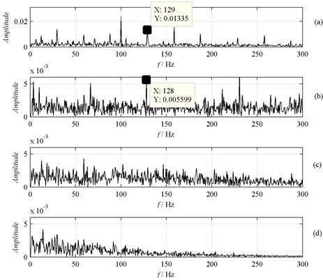
The signals are transformed by fast Fourier and Hilbert to obtain the frequency and frequency demodulated spectrum, as shown in Fig. 7. The amplitude spectrum of , and are obtained from IAs of these PF components via FFT, as shown in Fig. 8. It can be observed that the spectral line at 129 Hz is found clearly. Considering the rotaroy speed is approximate and ball sliding, this spectral line can be used as the ball defect frequency. Consequently, when the fault is serious, all the methods can diagnose the fault effectively.
4. Summary an conclusions
LMD can decompose the multi-component modulation signals into a finite set of mono-components, and the PF component can truly reflect the original signal information. In this paper, the LMD method is applied to analyze the vibration acceleration signals of a faulty bearing with different bearing element faults. And the result is compared with those obtained from traditional envelope demodulation method. The analysis results of the synthetic signal and measured signal indicate following conclusions. 1) LMD method is superior to the envelope demodulation method in analysis of signals of low SNR, especially early ball defect; 2) LMD method can decompose the rolling element fault feature information from the original signals and extract fault characteristics. It can not only determine fault types effectively, but also avoid miscalculation to some extent.
References
-
Lu S., Li M. Bearing fault diagnosis based on PCA and SVM. Proceedings of the International Conference on Mechatronics and Automation, 2007, p. 3503-3507.
-
Liu W., Han J., Jiang J. A novel ball bearing fault diagnosis approach based on auto term window method. Measurement, Vol. 46, 2013, p. 4032-4037.
-
Zhang Y., Ai S. EMD based envelope analysis for bearing faults detection. Proceedings of the 7th World Congress on Intelligent Control and Automation, 2008, p. 4257-4260.
-
Kankar P., Sharma S., Harsha S. Rolling element bearingfault diagnosis using wavelet transform. Neurocomputing, Vol. 74, 2011, p. 1638-1645.
-
Cohen L. Time-frequency analysis. Prentice-Hall, Englewood Cliffs, NJ, 1995.
-
Li H., Zhang Y. Bearing faults diagnosis based on EMD and Wigner-Ville distribution. Proceedings of the 6th World Congress on Intelligent Control and Automation, 2006, p. 5447-5451.
-
Prabhakar S., Mohanty A., Sekhar A. Application of discrete wavelet transform for detection of ball bearing race fault. Tribology International, Vol. 35, 2002, p. 793-800.
-
Cheng J., Yu D., Yang Y. A fault diagnosis approach for roller bearings based on EMD method and AR model. Mechanical Systems and Signal Processing, Vol. 20, 2006, p. 350-362.
-
Smith J. The local mean decomposition and its application to EEG perception data. Journal of the Royal Society Interface, Vol. 2, 2005, p. 443-454.
-
Cheng J., Yang Y. A rotating machinery fault diagnosis method based on local mean decomposition. Digital Signal Processing, Vol. 22, 2012, p. 356-366.
-
He T., Liu X., Shan Y., Pan Q. Rolling element defect diagnosis based on local mean decomposition. Applied Mechanics and Materials, Vol. 117-119, 2012, p. 33-37.
-
http://csegroups.case.edu/bearingdatacenter/pages/welcome-case-western-reserve-university- bearing-data-center-website.
About this article

This work was finically supported by the National Science Foundation of China (Grant No. 51105018) and Beijing Higher Education Young Elite Teacher Project (Grant No. YETP1116).
