Abstract
Vibration fatigue is describing the engineering material fatigue which is caused by forced vibration of random nature. Typically, the excited structure is usually subjected to arbitrary variable amplitude loading spectrums in the fatigue weakness area. Due to high nonlinearity of the fatigue damage evolution, it is extremely difficult to analyze the fatigue process under the vibration loading by cycle-based method in the time-domain. So, in this paper a time-based method is proposed to analyze the fatigue crack growth behavior under arbitrary variable amplitude loading. This approach is based on the crack tip opening displacement (CTOD) estimation, crack closure model and the fatigue damage evolution function. A set of fatigue experimental data for Al7075-T6 under “Christmas Tree” loading, a typical vibration loading spectrum, is used to validate the method. The predictions of fatigue life under arbitrary load spectra match the testing data very well. Moreover, the simulation under a random loading is employed to demonstrate the verification of this formulation.
1. Introduction
Vibration fatigue theory has been introduced to deal with the fatigue behavior under any kinds of arbitrary vibration loading. Many structures components are frequently subjected to vibration loading of random nature. Since fatigue is one of the predominant mechanical failure causes, fatigue life prediction has become a necessary subject in many researches [1-3]. The approach of predicting fatigue life could be divided into frequency domain and time domain. The time domain methods are based on the cycle counting and cumulative damage rules [4]. The identification of cycles is usually carried out through the rainflow counting method [5]. And then the Miner damage accumulation rule is used to perform the accumulation of damage. The time domain has been widely accepted to predict the fatigue life. However, when a component is subject to variable amplitude loading, the cycle calculation will be very time consuming. In addition, the variable load interaction has the influence on the fatigue crack growth behavior which the most of the existing time domain methods cannot account for [6]. Therefore, our investigation in this paper focuses on the time-based model development aim to predict the fatigue crack behavior of components subjected to arbitrary variable amplitude loading.
Many models have been proposed to predict the fatigue crack propagation under variable amplitude loading. Elber proposed the approach to describe the crack growth behavior, which considers crack closure [7]. Wheeler [8] and Willenborg [9] presented a series of models based on the plastic zone size ahead of the crack tip. The fatigue crack growth computer program developed by Forman et al. could be used to estimate for constant and variable amplitude loading [10]. Most studies involve the nonlinear analysis of cyclic plasticity and crack contact analysis, which causes the computing process of the random variable amplitude loadings situation extremely complicated.
In many recent studies, the CTOD variation concept has been indicated to correlate with the fatigue crack growth rate under cyclic loadings [11, 12]. Liu, Lu and Xu proposed a theoretical CTOD formulation under variable amplitude loading [14]. In addition, Zhang and Liu performed a state-of-art in-situ SEM testing and presented a virtual crack annealing model to calculate the crack closure which has the effect on the CTOD variation [12, 13]. Based on that, Zhang and Liu developed a time-based fatigue crack growth model to predict the fatigue crack behavior under variable amplitude loading, which combine the CTOD variation estimation with the crack closure model [15]. Through this model, the CTOD variation at any loading level can be obtained.
The paper is organized as follows. First, the model to calculate the CTOD variation which is combined with the crack closure model and the fatigue damage evolution function is briefly derived. Based on this method, the fatigue crack growth rate can be estimated. Next, the fatigue testing of Al 7075-T6 under “Christmas Tree” loading has been performed to verify this formulation. By using the “Christmas Tree” loading, the high ratio and low ratio situation will be discussed. The predictions of the proposed approach match the experimental data very well. Moreover, the method will be simulated under random loading. Finally, some conclusions are given based on the current investigation.
2. Methodology
It is proven that CTOD variation correlates with the fatigue crack propagation. The analytical solution of CTOD could be expressed as [16]:
where is the Young’s modulus, and is the yield strength. is the stress intensity factor (SIF), which can be expressed as [17]:
where is the crack length and is the plate width.
A general mathematic calculation of CTOD under random cyclic loading is derived in paper [14]. And then the crack closure is considered. It is proven that the crack closure is an important factor of the fatigue crack growth behavior through the fatigue testing and theoretical analysis [12, 13]. Therefore, Zhang and Liu modified the formulation above [15]. Based on a stationary crack, the mathematic estimation of CTOD variation with crack closure during the reloading path and unloading path can be expressed as [15]:
where indicates the crack closure loading level at the th peak or valley. is the Heaviside step function. If the or is smaller than , the crack will close and CTOD will remain constant.
All the derivation above is based on the stationary crack. For the practical crack, the total CTOD variation considering the crack growth can be written as [15]:
Therefore, the general calculation for CTOD can be expressed as [15]:
In order to predict the fatigue crack propagation, the simple mathematical model is present in paper [15]. The instantaneous crack growth rate can be expressed as [15]:
where is a fitting parameter. Based on the formulation above, the crack length incremental at any point during the cyclic loading can be written as [15]:
3. Model validation
3.1. Model validation using “Christmas Tree” loading spectrum
In this section, the model above will be validated through comparing the predictions with the experimental data. The Fig. 1 shows the type of vibration loading spectrum, which could be considered as the superposition of two loading spectra.
Therefore, the “Christmas Tree” loading spectrum is employed to verify the model. Zhang and Liu provided fatigue test data for edge-cracked 7075-T6 aluminum alloy specimen under variable amplitude loading [15]. The geometric dimensions of the specimen are respectively: thickness 4.7 mm, width40 mm. The geometric factor of the stress intensity factor for this specimen is:
Fig. 1Schematic illustration of the vibration loading spectrum
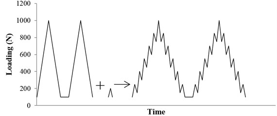
Fig. 2“Christmas tree” loading profile
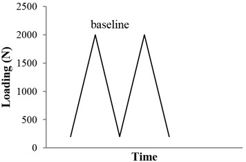
a) Baseline loading spectrum
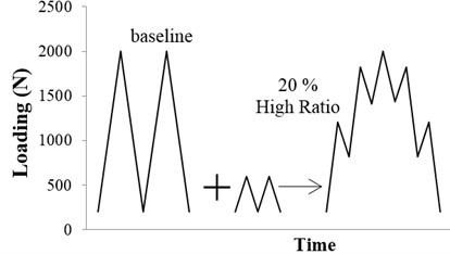
b) 20 % high ratio spectrum
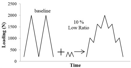
c) 10 % low ratio spectrum
Fig. 3Comparison of the model predictions with experimental results
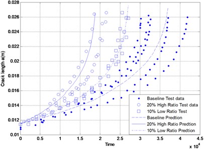
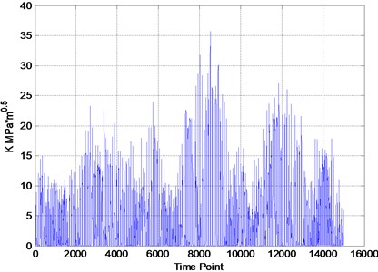
Fig. 4Schematic of the variable amplitude loading
The experimental loading spectra are shown in Fig. 2. The typical arbitrary load spectrum situation is included in the “Christmas Tree” spectra. The vibration is treated as loading spectrum to affect the fatigue crack propagation behavior.
The model predictions are compared to the test data in Fig. 3. It is obvious that the predictions match the experimental data very well. The present formulation provides a good estimate of fatigue crack growth under arbitrary amplitude loading.
3.2. Model predictions under random loading
In this section, the simulation of the model above will be illustrated. The variable amplitude loading spectrum is shown in Fig. 4.
According to the Eq. (5), the CTOD variation under variable amplitude loading is calculated and shown in the Fig. 5. When the is less than , the crack is closed and the CTOD remains constant.
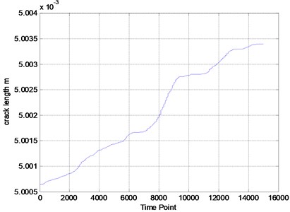
More detailed information can be obtained in the - curve in Fig. 6, which shows the crack growth rate under the variable amplitude loading.
Fig. 5CTOD variation under variable amplitude loading
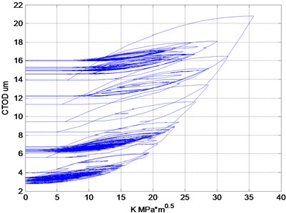
Fig. 6Simulation of the model
4. Conclusions
The fatigue crack growth behavior under random vibration loading is usually accounted for by analyzing the fatigue properties. The vibration is treated as the loading history or loading spectrum to affect the crack propagation. Therefore, the time-based fatigue crack growth model is described in this paper to predict the fatigue crack growth under variable amplitude loading. This model is based on the CTOD variation, which is combined with the crack closure. The following conclusions can be drawn:
The time-based method is proven to predict the fatigue life under variable amplitude loading easily, accurately and successfully through the fatigue testing and the simulation validation. Furthermore, this model avoids complex calculation process and cycle counting, which is different from the existing method.
The model validation using “Christmas Tree” is performed and very good correlations are observed between model predictions and experimental observations.
During the vibration cycles, the loading frequency has effects on the crack growth. However, the frequency factor is not considered in this investigation. In the future, the method should be extended by taking account of the frequency influence.
References
-
Yan-Shin Shih, Guan-Yuan Wu Effect of vibration on fatigue crack growth of an edge crack for a rectangular plate. International Journal of Fatigue, Vol. 24, Issue 5, 2002, p. 557-566.
-
Liou H. Y., Wu W. F., Shin C. S. A modified model for the estimation of fatigue life derived from random vibration theory. Probabilistic Engineering Mechanics, Vol. 14, 1999, p. 281-288.
-
Mark Paulus, AbhijitDasgupta Semi-empirical life model of a cantilevered beam subject to random vibration. International Journal of Fatigue, Vol. 45, 2012, p. 82-90.
-
Dattoma V., Giancane S., Nobile R., Panella F. W. Fatigue life prediction under variable loading based on a new non-linear continuum damage mechanics model. International Journal of Fatigue, Vol. 28, Issue 2, 2006, p. 89-95.
-
Downing S. D., Socie D. F. Simple rainflow counting algorithms. International Journal of Fatigue, Vol. 4, Issue 1, 1982, p. 31-40.
-
Chang J. B. Round-robin crack growth predictions on center-cracked tension specimens under random spectrum loading. Methods and models for Predicting Fatigue Crack Growth, ASTM STP 748, American Society for Testing and Materials, Philadelphia, 1981, p. 3-40.
-
Wolf Elber Fatigue crack closure under cyclic tension. Engineering Fracture Mechanics, Vol. 2, Issue 1, 1970, p. 37-45.
-
Wheeler O. E. Spectrum loading and crack growth. Journal of Basic Engineering, Vol. 94, Issue 1, 1972, p. 181-186.
-
Willenborg J., Engle R. M., Wood H. A. A crack growth retardation model using an effective stress concept. Air Force Flight Dynamics Laboratory, 1971.
-
Forman R. G., Shivakumar V., Newman Jr J. C. Fatigue-crack-growth computer program. JSC-22267, NASA, 1986.
-
Lu Z, Liu Y. Small time scale fatigue crack growth analysis. International Journal of Fatigue, Vol. 32, Issue 8, 2010, p. 1306-1321.
-
Zhang W., Liu Y. Investigation of incremental fatigue crack growth mechanisms using in situ SEM testing. International Journal of Fatigue, Vol. 42, 2012, p. 14-23.
-
Wei Zhang, Yongming Liu In situ SEM testing for crack closure investigation and virtual crack annealing model development. International Journal of Fatigue, Vol. 43, 2012, p. 188-196.
-
Liu Y., Lu Z., Xu J. A simple analytical crack tip opening displacement approximation under random variable loadings. International Journal of Fracture, Vol. 173, Issue 2, 2012, p. 189-201.
-
Zhang W., Liu Y. A time-based formulation for real-time fatigue damage prognosis under variable amplitude loadings. Structures, Structural Dynamics and Materials Conference, Vol. 4, p. 3231-3241.
-
Srawley J. E. Wide range stress intensity factor expressions for ASTM E 399 standard fracture toughness specimens. International Journal of Fracture, Vol. 12, Issue 3, 1976, p. 475-476.
-
Brown W. F., Srawley J. E. Plane strain crack toughness testing of high strength metallic materials. ASTM STP 410, 1966, p. 30-33.
About this article

The research is financially supported by the National Natural Science Foundation of China No. 51405009.
