Abstract
Electro-hydraulic shake tables (EHSTs) are indispensable equipments in laboratory for evaluating structural performance subject to vibration environment. A novel feedforward inverse control with disturbance observer strategy is proposed in this paper in order to improve the acceleration tracking performance of the EHST system. The EHST system is firstly controlled by the three variable controller (TVC) to obtain a coarse time waveform replication accuracy, and then the parametric transfer function of the TVC controlled EHST system is identified with the H1 estimation method and complex curving fitting technology. Next, the zero magnitude error tracking control technology is employed to deal with the estimated non-minimum phase transfer function so as to design a stable and casual inverse model, and the proposed controller comprised of feedforward inverse controller and disturbance observer is further established based on the designed inverse model. Therefore, the proposed algorithm combines the virtues of feedforward inverse control and disturbance observer. The proposed algorithm is firstly programmed by MATLAB/Simulink software and then is compiled to an Advantech computer with real-time operating system for implementation. Finally, experiments are carried out on a unidirectional EHST system and the results demonstrate that a better acceleration tracking performance is achieved with the proposed controller than with the other conventional controllers.
1. Introduction
Shake tables provide the most direct experimental methods in laboratory for the assessment of structures subject to vibration circumstances [1], and therefore are extensively applied in civil engineering structures [2], automobile industry [3], earthquake-proof testing [4], etc. Compared with other types of drive, the electro-hydraulic shake table (EHST) has the merits of remarkable power density, higher velocity, superior precision, larger actuating forces and lower cost [5].
The control purpose of the EHST system is to reproduce the reference acceleration signal at table. However, due to the inherent nonlinear properties of the whole system, such as valve dynamics, dead zones, spherical joint intervals, frictions, etc [6], the control performance of the EHST system is not satisfactory and acceptable. Hence, these factors must be well considered and compensated during the controller design process to ensure a feasible acceleration replication performance.
Due to the fact that direct acceleration feedback control of hydraulic actuators is naturally unstable and usually results in table drift [7], the currently existed control scheme is often operated in the displacement-controlled form, where the reference displacement is obtained by double integrating the acceleration signals. As a benchmark for EHST systems, the three variable controller (TVC) based on zero pole assignment [8, 9] is proposed to deal with the hydraulic resonance by replacing the unwanted system’s dynamics with the designer’s expectation. To further enhance the acceleration tracking performance, Twitchell and Symans [10] presented the feedforward inverse compensation strategy with the direct use of the inverse transfer function from the reference displacement to the measured displacement. De Cuyper et al. [11] put forward the iterative learning control (ILC) method employed in many commercial shake tables. The basic principle of the ILC strategy is to repeatedly shape the command signal by adding a fraction of the acceleration tracking error filtered through the measured inverse frequency response function (FRF), and this method is further improved by Cherng et al. [12] with a weighting function that is created by normalizing the FRF so as to shorten the error-minimising iteration procedure. All the above mentioned methods are classified as the command shaping policies, and have the advantages of easy implementation and can improve the acceleration tracking performance in both time and frequency domains.
In addition to the command shaping strategies, the adaptive control policies are adopted to deal with varying dynamic behavior during the control process. The most celebrated minimal control synthesis (MCS) algorithm firstly proposed by Stoten in 1990[13] is applied to the EHST system to cope with internal parameter variation, external disturbances, and nonlinear dynamics [14, 15], and the conventional MCS algorithm is further extended to velocity MCS (vMCS) scheme by Gizatullin and Edge [16]. Yao et al. [17] presented an adaptive notch filter based on the least mean square algorithm (LMS) to cancel out the acceleration output harmonic for EHST system with sinusoidal input, and experiments are conducted on a real EHST system to validate the efficiency of reducing the total harmonic distortion. Karshenas et al. [18] exploited the adaptive inverse control (AIC) scheme, which approximates the inverse model of shake tables with a finite impulse response and updates the filter weights by standard filtered-x LMS algorithm. Shen et al. [19] combined the AIC strategy with the feedforward inverse controller, where the feedforward inverse controller is firstly used to extend the system’s bandwidth in the inner loop and then the AIC is employed in the out loop to compensate for the system’s modeling errors and uncertainties, and this combined algorithm is further improved by sythesis of the internal model control (IMC) algorithm [20]. Despite the above mentioned typical control methods, the efforts in finding a more accurate strategy with easy implementation for EHST systems are still continuing.
In this paper, a feedforward inverse control with disturbance observer strategy is proposed for the high fidelity acceleration tracking of EHST system. The parametric system model of the EHST system controlled by TVC controller is firstly estimated by the H1 method and complex curve fitting algorithm, and then the zero magnitude error tracking control (ZMETC) technology is employed to deal with the identified non-minimum phase (NMP) system so as to obtain a stable inverse controller. With the designed stable inverse controller, the proposed controller is finally constituted by combining the feedforward inverse model and the inverse model based disturbance observer.
The rest of this article is organised as follows. The modeling of hydraulic actuating system for the unidirectional EHST system is firstly discussed in Section 2. Next, Section 3 introduces the detailed theories and implementation of the TVC and the proposed controller. Then, in Section 4 experiments are conducted and the results are discussed to analyze the effectiveness of the proposed algorithm. Finally, Section 5 concludes the main points and contributions.
2. Shake table modeling
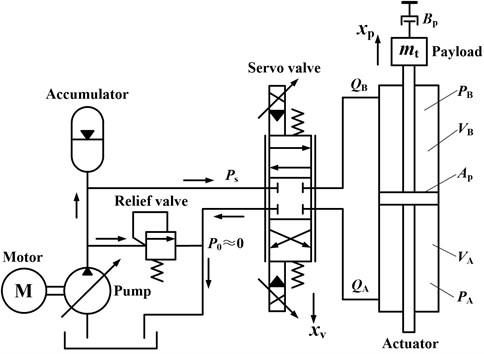
The working principle of the unidirectional EHST system is presented in Fig. 1, in which the double ended hydraulic actuator is controlled by a three-land-four-way spool valve. According to Merritt’s description [21], the load flow equation, flow continuity equation and the force balance equation can be respectively written as follows:
where is the spool displacement of the servo valve, is the pressure drop across the load defined as , is the linearized flow gain coefficient, is the linearized flow pressure coefficient, is the effective area of the actuator, is the actuator displacement, is the total leakage coefficient, is the effective bulk modulus, is the total chamber volume, is the total mass of piston and load referred to the piston, is the viscous damping coefficient.
Fig. 1Simplified schematic diagram of valve controlled actuator for EHST system
Noticing the fact that and employing Eq. (2-3), the open loop transfer function from the valve displacement to the actuator displacement can be derived as follows:
where is the total flow-pressure coefficient defined as , is the valve flow gain denoted as is the hydraulic natural frequency represented as is the damping ratio of the actuator expressed as .
3. Controller design
3.1. Three variable controller
The basic close loop acceleration control scheme of EHST system is depicted in Fig. 2. As can be seen from Fig. 2, the whole control strategy is comprised of a reference signal generator and the TVC controller. Since the direct acceleration feedback control of EHST system is inherently unstable and usually gives rise to table drift, to solve this problem, the signal generator is firstly employed to generate the reference displacement of the actuator by double integrating the acceleration time history and removing the drifting components, and then the generated displacement is further utilized to constitute the close loop control scheme based on displacement feedback. The transfer function of the signal generator can be expressed as:
where , and are selected in this paper to prevent the table from moving outside the maximum stroke of the cylinder when acceleration in very low bandwidth is applied.
Fig. 2Control diagram of EHST system with TVC controller
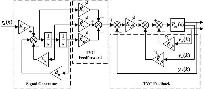
The TVC controller consisting of TVC feedback and feedforward components is adopted to stabilize the EHST system and to enhance the tracking accuracy. It can be easily found in Fig. 2 that the TVC feedback component requires the system’s displacement, velocity, and acceleration information, and the displacement and acceleration signal can be directly obtained with sensors. As for the velocity information, it is synthesized by the collected displacement and acceleration signal passing through a low-pass filter and a high-pass filter respectively. The principle of TVC feedback controller is to replace the system’s dynamics with the designer’s expectation, and therefore the TVC feedback coefficients can be calculated as:
where is the desired acceleration bandwidth, is defined as and .
The TVC feedforward component is exploited to extend the system’s bandwith and to improve the tracking performance by canceling out the poles of the system close to the image axis, and hence based on this principle, the TVC feedforward coefficients can be derived as follows:
and then the transfer function of the EHST system controlled by the TVC controller from the reference acceleration input to the actual acceleration output is obtained as:
3.2. System identification and inverse controller design
Due to the fact that determination of the modeling parameters of the EHST system is a tough task, especially for the hydraulic parameters, and therefore the system identification method is adopted for obtaining the parametric transfer function of EHST system controlled by TVC controller so as to conduct the proposed model based control scheme. The reference excitation signal and the actual output of the TVC controlled EHST system are collected firstly, and then the frequency response data sequence (FRDS) of the system can be calculated using the H1 estimation method described as follows:
where is the cross power spectral density of reference and output acceleration signals, is the power spectral density of the reference signals.
The time invariant discrete system model denoted by ratio of two frequency-dependent polynomials is exploited to represent the EHST system in the form of:
Employing the complex curve fitting technology [22] to Eq. (9-10), the coefficients of the numerator and denominator of Eq. (10) can be readily solved and hence the identified parametric system model is obtain.
However, due to the sampling holders and physically non-collocated sensors and actuators of the control system, the identified discrete model always contains NMP zeros and directly reversing the estimated numerator and denominator will result in an unstable inverse controller. To deal with the NMP zeros, the ZMETC technology can be utilized to form an approximate inverse controller by transforming the NMP zeros of the system into stable poles. The first step to design a stable inverse model with ZMETC technology is to partition the identified system model into NMP and MP polynomials as follows:
where is the identified numerator polynomial, is the identified denominator polynomial, is the polynomial containing all the MP zeros, is the polynomial including all the NMP zeros and can be written as:
and the stable inverse controller employing ZMETC technology can then be obtained as [23]:
where units of delay is added to ensure the casuality of the inverse controller, has poles inside the unit circle by inversing the coefficients of polynomial and can be described by:
3.3. Proposed controller design
The proposed feedforward inverse control scheme with disturbance observer is demonstrated in Fig. 3, from which it can be obviously found that a disturbance observer employing the above designed inverse system model is firstly applied to the TVC controlled EHST system for the suppression of disturbances, and then a feedforward inverse controller is cascaded to the disturbance observer to further enhance the tracking performance. Since the system modeling error always occurs during the identification process, the multiplicative uncertainty is adopted to represent the modeling errors and the relation between the estimated and actual EHST system can be expressed as:
where and are the actual and estimated system model respectively.
Fig. 3Proposed feedforward inverse controller with disturbance observer for EHST system
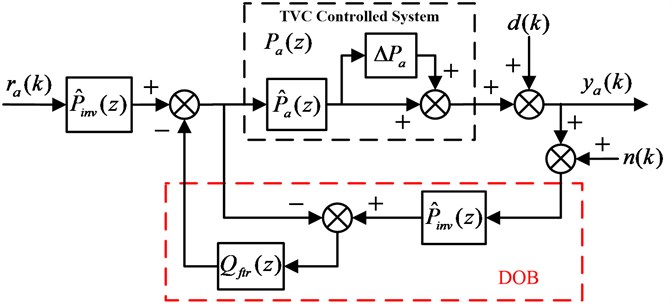
Simplifying the block diagram of Fig. 3, the following three transfer functions can be easily derived:
where is the transfer function from the reference acceleration input to the acceleration output signal , is the transfer function from the external disturbance to the acceleration output signal , is the transfer function from the sensor noise to the acceleration output signal .
As the design process of the inverse model for estimated EHST system is offline, the error of the designed inverse model with ZMETC technology is neglectable during the frequency of interest, and therefore the following equation can be obtained:
Combining Eq. (16-19) and simplifying yields:
Since the external disturbances usually exist in the low bandwidth range and the measured sensor noise in the high bandwidth range, if the filter satisfies the requirement:
then the following conclusions can be drawn:
which indicates that the disturbances are suppressed in the low frequency range and the measured sensor noises are restrained in the high frequency range.
Referring to Eq. (21), the filter exhibits a low-pass property, and hence usually a two-order low pass filter with bandwidth is chosen as follows:
and the robust stability of the proposed feedforward inverse controller with disturbance observer scheme is given as [24]:
where stands for the H-infinity norm.
4. Experiments and discussion
4.1. Experimental setup
The unidirectional EHST system for the evaluation of the proposed algorithms is exhibited in Fig. 4. As can be observed from Fig. 4, the adopted EHST system mainly consists of a platform, an actuating cylinder, a reaction base, a MOOG two-stage servo valve, a Germanjet magnetostrictive displacement sensor, a PCB accelerometer and a payload. The reaction base provides a workable solid anchor for all the other components, on which two Hiwin low-friction linear guideways with four sliders are bolted, and the platform is placed on top of the four sliders. The actuating cylinder has a 70 mm bore and 50 mm rod and is connected to the profile of the platform and the end of the reaction base through two spherical joints, respectively. The Moog two stage servo-valve with a 38 L/min flow capacity at 7 MPa supply pressure (Type: G761-3004b) is installed on the cylinder to control its movements. The displacement sensor is attached beneath the cylinder and the accelerometer is installed on the drive rod of the cylinder. The main parameters of EHST system are listed in Table 1.
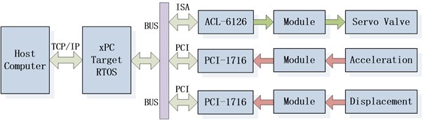
The scheme of the EHST hardware system architecture is briefly depicted in Fig. 5, where the xPC rapid prototype technology is employed for the control of the whole system. The xPC target technology consists of a host and a target computer. The target is an Advantech industrial computer installed with the xPC target real time operating system (RTOS) and the A/D and D/A cards. The host is a personal laptop with the MATLAB, Simulink, Microsoft Visual Studio software. The host and the target is communicated by the Ethernet through a cross twisted-pair cable. The acceleration and displacement signals are firstly converted and amplified by the conditioning module to –10 V~+10 V signals, and then is collected by the 16-bit Advantech A/D card PCI-1716 on the target computer. The servo valve control signal is sent by the target computer through the 12-bit Adlink D/A card ACL-6126 before it is transformed by the servo valve conditioning module to –40 mA~+40 mA. The control algorithms are firstly programmed by the MALAB/Simulink and compiled by Visual C on the host, and then is downloaded to the target for real time execution. The sampling rate of the whole control system is selected as 1000 Hz.
Fig. 4Experimental setup for the EHST system
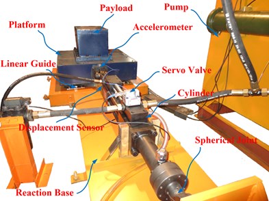
Table 1Main parameters of the unidirectional EHST system
Parameter | Value | Parameter | Value |
Platform size | 0.8 m×0.8 m | Platform weight | 380 kg |
Payload | 150 kg | Driving type | Electro-hydraulic |
Control type | Acceleration, position | Actuator stroke | ±100 mm |
Maximum velocity | 0.34 m/s | Acceleration range | ±2 g |
Fig. 5Hardware system architecture of the EHST system
4.2. Results and discussion
At the initial stage of the experiment, the unidirectional EHST system is tuned by the TVC controller to achieve a moderate acceleration tracking performance. Due to the fact that the TVC controller is the foundation for the subsequent controller design, the parameter tuning procedure of the TVC controller is described elaborately. The displacement feedback controller is firstly adopted to stabilize the whole system and the parameter is online tuned by gradually increasing its value from a relatively small starting value. During the tuning of the feedback parameter, a 60 Hz random signal with amplitude 5 mm is exploited to evaluate the performance of different and by comparing the position frequency response of the EHST system, it can be concluded that when a small is adopted , the magnitude property of the system is far below the 0 dB line and with the increase of , the magnitude comes closer to the 0 dB line, which indicates that a better position tracking accuracy is obtained. However, the increase of is limited owing to the low damping ratio of the hydraulic system and overlarge will result in unstable performance. Therefore, the rising rate of the displacement feedback parameter should exhibit a gradually decreasing trend. Based on these principles, the tuned displacement feedback parameter at this stage is and the corresponding position frequency response is presented in Fig. 6.
The blue solid line in Fig. 6 is the position frequency response of the EHST system with only displacement feedback control (), and there exists a peak at the frequency 32 Hz. This peak represents the system’s hydraulic resonance due to the system’s low damping ratio, and it affects the further increasement of the displacement feedback parameter . To cope with this problem, the acceleration feedback control is employed.
Fig. 6Position frequency response of the EHST system with and without acceleration feedback
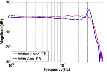
a) Magnitude property
b) Phase property
The tune of the acceleration feedback parameter also starts with a small initial value, and since the addition of acceleration feedback causes gain reduction of the whole system, the displacement feedback parameter should also be increased to compensate for the gain reduction. This process continues until any further increasement of these two parameters leads to an unstable system, and the final obtained parameters are and . As the velocity signal cannot be directly obtained, the velocity feedback is not adopted in the real system and this does not cause much performance degradation. The position frequency response with acceleration feedback is shown as the red dotted line in Fig. 6, from which it can be obviously found that the hydraulic resonance is eliminated and the system’s performance is improved.
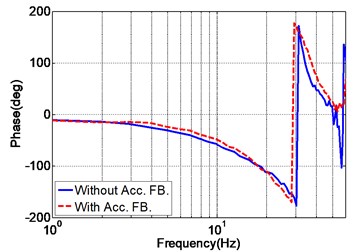
The purpose of TVC feedforward controller is to extend the system’s bandwidth and to enhance the acceleration tracking performance. During the tuning of feedforward parameters, the displacement feedforward parameter is always set as . As for the acceleration parameter , the increase of leads to the extension of system bandwith, however larger magnitude mismatch error will be generated. The velocity parameter is therefore combined to compensate for the magnitude mismatch in the cost of bandwidth. Hence, the acceleration and velocity feedforward parameters should be online tuned with the consideration of mutual effect, and the final obtained parameters are listed in Table 2. The acceleration frequency response of the EHST system with and without TVC feedforward is also depicted in Fig. 7, and as demonstrated in Fig. 7, the frequency response of the EHST system is greatly improved by the TVC feedforward controller.
Table 2Online well-tuned parameters of the TVC controller
Parameter | Value | Parameter | Value |
Disp. FB. () | 22.5 | Velo. FB. () | 0 |
Acc. FB. () | 0.025 | Disp. FF. () | 1 |
Velo. FF. () | 0.84 | Acc. FF. () | 0.00053 |
Fig. 7Acceleration frequency response of the EHST system with and without TVC feedforward
a) Magnitude property
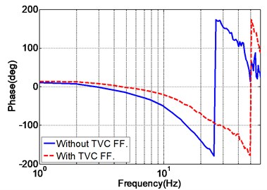
b) Phase property
After the EHST system is well-tuned by the TVC controller, a random acceleration signal with magnitude 0.5 g and frequency range 2-100 Hz is applied to the TVC controlled system, and the actual measured acceleration output signal is collected for system identification. With the above mentioned identification algorithm, the discrete transfer function of the TVC controlled system model can be expressed as:
To effectively evaluate the accuracy of the identified system model, the frequency response of the experimental and identified EHST system is depicted in Fig. 8. It can be obviously observed from the figure that the estimated system model well matches the experimental result calculated by H1 method with a Hanning window and 50 % overlap during the frequency of interest for both the magnitude and phase property. Therefore, the identified system can be further utilized for model based control strategy.
Fig. 8Frequency response of the experimental and identified EHST system model
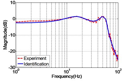
a) Magnitude property
b) Phase property
As the nominal model of EHST system is acquired by the identification algorithm, the next work is to design a stable inverse model so as to constitute the proposed controller. By carefully observing Eq. (25), it is found that the estimated system model contains three NMP zeros outside the unit circle, i.e. and , and the ZMETC technology whose basic idea is to transforming the NMP zeros inside the unit circle is exploited and finally the stable inverse controller can be derived as follows:
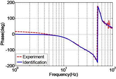
The frequency response of the identified EHST system and the designed inverse model is presented in Fig. 9 so as to analyze the effectiveness of the designed inverse controller. As can be inferred from Fig. 9, the magnitude response of the design inverse model is consistent with the ideal inverse model, while the phase response error increases with the augment of the frequency. Despite of the phase error occurred for the designed inverse model, it still can well compensate for the system dynamics for both magnitude and phase responses during the frequency of interest.
Fig. 9Frequency response of the identified EHST system and designed inverse model
a) Magnitude property
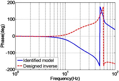
b) Phase property
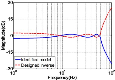
Fig. 10 presents the experimental frequency responses of the unidirectional EHST system controlled by TVC controller, feedforward inverse controller and the proposed controller, respectively. It can be observed from Fig. 10(a), for the magnitude property, the TVC controller has the worst performance with system bandwidth approximately 60 Hz, and with the inverse controller the system’s bandwidth is greatly extended to some extent, and the best magnitude performance is obtained by the proposed controller. As for the phase property, Fig. 10(b) demonstrates that the phase delay phenomenon is effectively reduced with the inverse controller and the proposed controller. Therefore, it can be deduced from the frequency characteristics that the proposed controller has the ability of improving the acceleration tracking performance.
Fig. 10Frequency response of the experimental EHST system with different controllers
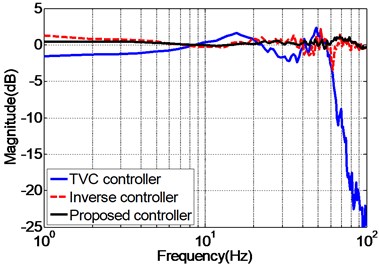
a) Magnitude property
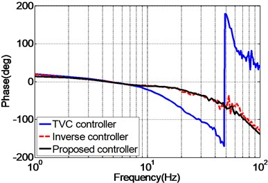
b) Phase property
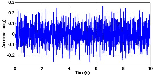
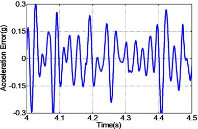
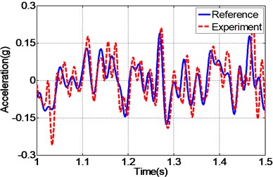
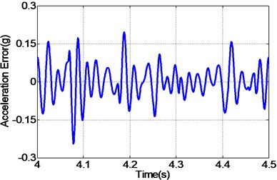
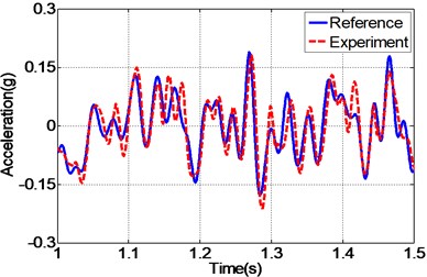
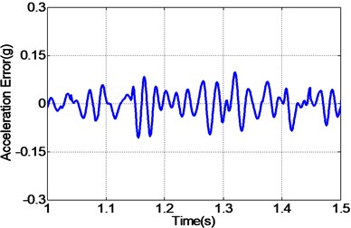
To clearly analyze the effectiveness of the proposed controller compared with other controllers, the same random reference acceleration signal with amplitude 0.5 g and frequency range 2-45 Hz is applied to the unidirectional EHST system controlled by different controllers. The time history of the reference acceleration signal lasting for 10 s is shown in Fig. 11, and the partially enlarged view of reference and the experimental results from 1s to 1.5 s together with the corresponding acceleration tracking errors are depicted in Fig. 12.
Fig. 11Random reference acceleration input signal
By carefully examing Fig. 12(a, c, e), it can be concluded that the EHST system controlled by TVC controller has the worst tracking accuracy caused by the large magnitude mismatch and the big phase delay, and this defect is then overcomed with the implementation of feedforward inverse controller to some extent, especially for the phase delay problem. Finally employing the proposed controller, the magnitude mismatch problem is further compensated and the best tracking accuracy is achieved. This fact is in high accordance with the case described by the acceleration error of different controllers in Fig. 12(b, d, f), from which we can find that the maximum acceleration error is obtained with the TVC controller and the minimum acceleration error is acquired with the proposed controller.
In order to quantitively compare the performance of different controllers for EHST system, the relative root mean square (RMS) index of the acceleration error between the reference and experimental result in time domain is adopted, and the computing formulation is expressed as:
Employing Eq. (27), the RMS index for the TVC controller, inverse controller and the proposed controller is calculated as 144.92 %, 90.87 % and 72.12 % respectively. Hence, the computed RMS index further indicates that the proposed controller has the advantage of a higher tracking accuracy than the other two methods with random input signals.
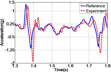
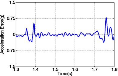
In addition to random acceleration input signal, to evaluate the correctness of the proposed controller, the real recorded earthquake happened in Baja California in 1987 is also employed to the unidirectional EHST system. Due to the physical limitation of the whole hydraulic system, the recorded earthquake wave is compressed by half in the duration time and the final scaled acceleration signal is exhibited in Fig. 13. After the earthquake wave is applied to the EHST system, the time history of the close up view of the reference earthquake acceleration and the experimental results are plotted in Fig. 14, where the acceleration error is also presented to intuitionally compare the tracking performance of different controllers.
As can be easily concluded from Fig. 14, when the input signal is the real recorded earthquake wave, the acceleration tracking performance is also limited for the TVC controller, and then with the inverse controller the amplitude mismatch and phase delay phenomenon is alleviated, and the best replication performance is obtained by the proposed controller. Employing Eq. (27), the computed RMS index for TVC controller is 100.37 %, and that is reduced to 59.24 % with the inverse controller, and finally the RMS index is improved to 40.82 % by the proposed controller, which also reveals that the highest acceleration tracking accuracy is achieved with the proposed controller.
Fig. 12Frequency response of the experimental EHST system with different controllers
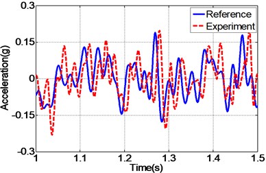
a) Time history by TVC controller
b) Error by TVC controller
c) Time history by inverse controller
d) Error by inverse controller
e) Time history by proposed controller
f) Error by proposed controller
Fig. 13Time compressed Baja California earthquake acceleration signal
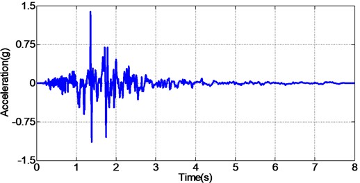
Fig. 14Frequency response of the experimental EHST system with different controllers
a) Time history by TVC controller
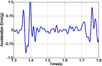
b) Error by TVC controller
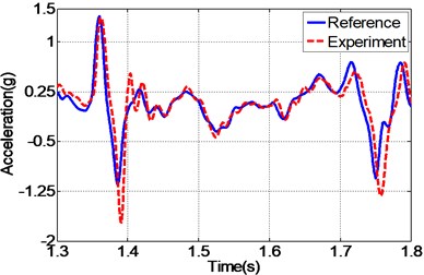
c) Time history by inverse controller
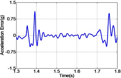
d) Error by inverse controller
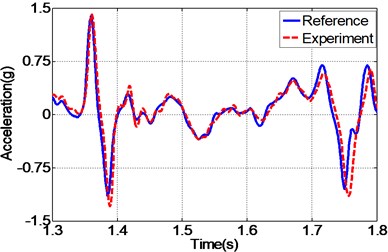
e) Time history by proposed controller
f) Error by proposed controller
5. Conclusions
This paper presents a novel feedforward inverse control with disturbance observer strategy for the acceleration tracking of EHST systems, and a series of experiments are conducted. The TVC controlled EHST system model is estimated by the H1 method and complex curving fitting technology, and the experimental results reveal that the identified model is in high accordance with the actual system. Then, with the ZMETC technology, the stable and casual inverse controller is achieved with high precision in contrast to the ideal one during the frequencies of interest. Finally, the proposed controller is established by combing the feedforward inverse controller and the inverse model based disturbance observer so as to cope with the uncertainties and disturbances, and the experiments indicates that the proposed controller has a better acceleration tracking performance than the other conventional controllers. It is also worth noting that the proposed algorithm can also be extended to servo control systems where high accuracy tracking is needed.
References
-
Severn R. The development of shaking tables – a historical note. Earthquake Engineering & Structural Dynamics, Vol. 40, Issue 2, 2011, p. 195-213.
-
Nakata N., Stehman M. Substructure shake table test method using a controlled mass: formulation and numerical simulation. Earthquake Engineering & Structural Dynamics, Vol. 41, Issue 14, 2012, p. 1977-1988.
-
Koch U., Wiedemann D., Ulbrich H. Model-based MIMO state-space control of a car vibration test rig with four electromagnetic actuators for the tracking of road measurements. IEEE Transactions on Industrial Electronics, Vol. 58, Issue 12, 2011, p. 5319-5323.
-
Plummer A. Control techniques for structural testing: a review. Proceedings of the Institution of Mechanical Engineers Part I-Journal of Systems and Control Engineering, Vol. 221, Issue 2, 2007, p. 139-169.
-
Yao J., Di D., Jiang G., et al. Acceleration amplitude-phase regulation for electro-hydraulic servo shaking table based on LMS adaptive filtering algorithm. International Journal of Control, Vol. 85, Issue 10, 2012, p. 1581-1592.
-
Kuehn J., Epp D., Patten W. High-fidelity control of a seismic shake table. Earthquake Engineering & Structural Dynamics, Vol. 28, Issue 11, 1999, p. 1235-1254.
-
Nakata N. Acceleration trajectory tracking control for earthquake simulators. Engineering Structures, Vol. 32, Issue 8, 2010, p. 2229-2236.
-
Tagawa Y., Kajiwara K. Controller development for the E-Defense shaking table. Proceedings of the Institution of Mechanical Engineers Part I-Journal of Systems and Control Engineering, Vol. 221, Issue 2, 2007, p. 171-181.
-
Xu Y., Hua H., Han J. Modeling and controller design of a shaking table in an active structural control system. Mechanical Systems and Signal Processing, Vol. 22, Issue 8, 2008, p. 1917-1923.
-
Twitchell B. S., Symans M. D. Analytical modeling, system identification, and tracking performance of uniaxial seismic simulators. Journal of engineering mechanics, Vol. 129, Issue 12, 2003, p. 1485-1488.
-
Cuyper J. D., Verhaegen M., Swevers J. Off-line feed-forward and H∞ feedback control on a vibration rig. Control Engineering Practice, Vol. 11, Issue 2, 2003, p. 129-140.
-
Cherng J. G., Goktan A., French M., et al. Improving drive files for vehicle road simulations. Mechanical Systems and Signal Processing, Vol. 15, Issue 5, 2001, p. 1007-1022.
-
Stoten D., Benchoubane H. Empirical studies of an MRAC algorithm with minimal controller synthesis. International Journal of Control, Vol. 51, Issue 4, 1990, p. 823-849.
-
Stoten D., Shimizu N. The feedforward minimal control synthesis algorithm and its application to the control of shaking-tables. Proceedings of the Institution of Mechanical Engineers Part I-Journal of Systems and Control Engineering, Vol. 221, Issue 3, 2007, p. 423-444.
-
Stoten D. P., Gómez E. G. Adaptive control of shaking tables using the minimal control synthesis algorithm. Philosophical Transactions of the Royal Society of London Series A-Mathematical Physical and Engineering Sciences, Vol. 359, Issue 1786, 2001, p. 1697-1723.
-
Gizatullin A., Edge K. Adaptive control for a multi-axis hydraulic test rig. Proceedings of the Institution of Mechanical Engineers Part I-Journal of Systems and Control Engineering, Vol. 221, Issue 2, 2007, p. 183-198.
-
Yao J., Di D., Han J. Adaptive notch filter applied to acceleration harmonic cancellation of electro-hydraulic servo system. Journal of Vibration and Control, Vol. 18, Issue 5, 2011, p. 641-650.
-
Karshenas M., Dunnigan M. W., Williams B. W. Adaptive inverse control algorithm for shock testing. IEE Proceedings, Control Theory and Applications, Vol. 147, Issue 3, 2000, p. 267-276.
-
Gang S., Zheng S. T., Ye Z. M., et al. Adaptive inverse control of time waveform replication for electrohydraulic shaking table. Journal of Vibration and Control, Vol. 17, Issue 11, 2010, p. 1611-1633.
-
Shen G., Zhu Z., Tang Y., et al. Combined control strategy using internal model control and adaptive inverse control for electro-hydraulic shaking table. Proceedings of the Institution of Mechanical Engineers Part C-Journal of Mechanical Engineering Science, Vol. 227, Issue 10, 2012, p. 2348-2360.
-
Merritt H. E. Hydraulic Control Systems. John Wiley & Sons Inc., New York, 1967.
-
Al Mamun A., Lee T., Low T. Frequency domain identification of transfer function model of a disk drive actuator. Mechatronics, Vol. 12, Issue 4, 2002, p. 563-574.
-
Butterworth J. A., Pao L. Y., Abramovitch D. Y. Analysis and comparison of three discrete-time feedforward model-inverse control techniques for nonminimum-phase systems. Mechatronics, Vol. 22, Issue 5, 2012, p. 577-587.
-
Zhao J., Shen G., Yang C., et al. Feel force control incorporating velocity feedforward and inverse model observer for control loading system of flight simulator. Proceedings of the Institution of Mechanical Engineers, Part I: Journal of Systems and Control Engineering, Vol. 227, Issue 2, 2013, p. 161-175.
About this article

This research was supported by the National Natural Science Foundation of China (Grant No. 51205392), Jiangsu Provincial Natural Science Foundation of China (Grant No. BK2012132), Program for Changjiang Scholars and Innovative Research Team in University (Grant No. IRT1292) and the Priority Academic Program Development of Jiangsu Higher Education Institutions. The authors would like to thank the editors, associate editors, and anonymous reviewers for their constructive comments.
