Abstract
The sorting arm structure is under the inertia impact of high frequency reciprocating motion. The vibration characteristics are related to the operation process so that the precision of the chip sorting is uncertain. Thus, the accuracy of chips and efficiency of LED sorting machine are reduced. In the paper, the relationship between the vibration of the sorting arm and the positioning error of the chip has been studied. Besides, the correlation between the sorting arm structure’s vibration and the working precision of the separator are pointed out. The operation control is optimized based on the dynamics of the sorting arm and the operation parameters are optimized based on time sequence setting, in order to shorten the vibration attenuation time of the sorting arm for suppress vibration and provide efficiency. The incentives, which are introduced by variable structure and by the operation, can be effectively controlled. The array accuracy of chips and working efficiency of chip sorting machine are improved.
Highlights
- The correlation between the sorting arm structure’s vibration and the working precision of the separator were clarified.
- The operation control was optimized, based on the dynamics of the sorting arm. The operation parameters were optimized based on time sequence setting.
- The incentives were introduced by the variable structure and by the operation, which were effectively controlled.
- The chip array accuracy and the working efficiency of the chip sorting machine were improved.
1. Introduction
As the LED market continues to expand, the demand for LED chip sorting equipment continues to increase [1]. The performance of sorting equipment also requires higher. Efficiency of the sorting equipment and precision of chip arrangement are the most important performance indexes, and high precision positioning control is the core technology of LED sorting equipment [2]. In order to ensure the efficiency and the precision, the research on the control technology of chip arrangement error is of great significance.
The methods of vibration suppression are divided into active and passive methods. Active inhibition is mainly divided into the following methods: such as PD feedback control method [3], optimal control method [4], transfer function method [5], inverse dynamics method [6], nonlinear decoupling method [7] Adaptive control methods [8] and so on. According to the principle of active control, it requires a complete test system, control system and implementing agencies composed of three parts. T. T. Soong first studied the active suppression and applied it to the civil engineering seismic design [9].
Passive inhibition can be broadly divided into two types: energy splitting method and energy dissipation method [10, 11]. Literature studies show that the particulate matter has damping characteristics, which can be used as an effective damping material and means in the field of passive vibration control [12-14]. Miles [15] applied confinement damping technology to the damping and noise reduction of Boeing 747 aircraft. This method is to add a layer of damping material on the surface of the structure, which is suitable for plate and shell structure. R. D. Friend [16] studied the vibration damping of cantilever beams by particle damping and discussed the factors that affect the energy consumption of vibration. The damping values of systems consisting of particle damping and cantilever are 50 % higher than other materials. Bai [17] studied the influence of temperature on the vibration of damping particles, which widened the application fields of particle damping, and he applied particle damping to extreme temperatures. K. W. Chan [18] successfully applied particle damping to the cantilever, but only placed the particle damper at the front of the cantilever, but he did not optimize the damped position on the cantilever.
There are also some studies on the servo drive system. George Younkin established a mathematical model which id three-ring and semi-closed-loop servo drive system, in which the speed and current controllers are proportional integral (PI) regulator. It has played an anti-disturbance role on the voltage fluctuation. However, he did not consider the filter link and the mathematical model of the inverter, his model is not precise enough [19]. Ping Ma [20] established a mathematical model of feedforward control three-ring semi-closed-loop of AC servo drive system, which considering the current controller, current amplifier, inverter and speed feedforward, but without considering the filter link and inverter, the model is not precise enough.
The above methods of suppressing vibration are mostly used in low speed structures or large mechanisms. However, the characters of high frequency reciprocating equipment are quick start and stop, short range, high frequency and multi-freedom reciprocating motion. The inertia introduced by the high frequency reciprocating motion will cause a huge shock and vibration. The paper takes the rotating arm of LED chip sorting machine as the research platform, the current major performance of this equipment is as follows.
Japan’s garter Corporation developed LED chip sorting machine (NST-620), whose sorting efficiency reaches 85 ms/chip and accuracy of / direction within ±30 μm [21]. The sorting machine (MS100PLUS) developed by ASM Pacific Technology Hong Kong, the sorting efficiency exceeded 70 ms/chip, the chip arrangement accuracy of ±1 mil. The sorting machine (M76FP) developed by Taiwan Wang Silicon Technology company whose XY positioning accuracy up to ±1 mil and less than ±3°angle [22]. The sorting machine (DH-LS420) developed by Zhicheng Huake Optoelectronics R & D whose sorting speed of 200 ms/chip, the arrangement accuracy up to ±1.5 mil and the angle less than ±3°.
Some universities and institutes have done some research on the vibration suppression of LED chip sorting equipment. Professor Anmin Xi designed a new institution in the sorting transfer system, and demonstrated in detail the correctness of this program. But he did not carry out a detailed experimental test on the scheme, and did not mention the sorting process and efficiency, and the index of the accuracy of the arrangement [23, 24].
Tao Wu successfully set up the chip sorting system. The sorting process and sorting strategy were studied in detail, and the sorting efficiency of the prototype was 1s/chip [25-27]. Cai Libin designed for high-precision control of sorting arm mechanism and put forward the use of external high-precision encoder to form a fully closed loop control strategy [28]. But he did not give the final positioning test results. His strategy is not completely closed loop because the actual pick-up chip position is at the end of the sorting arm. Wang Yingjun analyzed the elastic dynamic response of the sorting arm and designed the sorting arm by use of the FEA method and topological optimization method to meet the requirements of lightweight [29]. However, the article does not deal with sorting arm control strategy. According to the servo drive and servo parameters used by the sorting arm movement system, Wang Chengkai used SIMULINK to build the model of servo drive system, and then he carried out the simulation analysis and optimized the servo parameters [30]. Chen Zhenxing reduces the vibration of the sorting arm by the method of particle vibration suppression [31]. However, the particles must be placed at the end of the sorting arm, which increases the rotational inertia of the sorting arm. The efficiency of sorting cannot be guaranteed, and the requirements of the sorting equipment cannot be satisfied. Ouyang Jie proposed a modeling and simulation method based on the Dymola to optimize the parameters [32]. However, the optimized parameters are limited to the position loop gain and speed loop gain. Luo Bing proposed an autonomous docking method based on visual error feedback [33]. The position and attitude of the target were adjusted according to the difference between the camera imaging position and the ideal position. Liu Wenchao proposed a kind of intelligent compensation method based on the photogrammetric image processing to solve the cloth deformation of computer sewing machine [34]. Jia Dongyong proposed visual feedback control algorithm [35]. The position difference between the end of the arm and the object is regarded as a control factor, which is classified into closed-loop processing to correct systematic errors and to increase the stability of the system. Hu Xuxiao discusses the compensation scheme under linear deformation and discusses the visual calibration scheme under nonlinear deformation [36]. The experimental results show that more than 90 % of the error can be compensated for non-linear deformation of silicon.
The above studies are used visual recognition function, tracking the target, and feedback control. However, it lacks the requirements of real-time and efficiency. The real-time requirements of high-speed LED chips sorting system, which is based on visual feedback are high, and real-time error compensation is difficult. The purpose of this article is to suppress the vibration of the sorting arm. Based the analysis of the dynamics of the sorting arm on the arrangement error of the chip, this paper proposes the operation control mode of sorting arm in combine with the dynamics of sorting arm and the precision of chip sorting. This paper also presents the timing sequence’s optimal design of the sorting machine to improve the accuracy and efficiency of the machine.
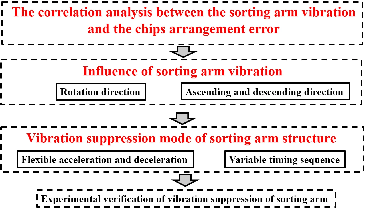
The paper is organized as follows. In Section 2, the correlation analysis between the sorting arm vibration form and the chip arrangement error is discussed. In Section 3, the vibration suppression mode of sorting arm structure in high-frequency reciprocating motion is studied. In Section 4, the experimental verification of vibration suppression of sorting arm is analyzed. In Section 5, a conclusion from the current research is presented.
2. The correlation analysis between the sorting arm vibration and the chips arrangement error
The various forms of sorting arm vibration in chip sorting process have different effects on chip arrangement accuracy and efficiency. On the basis of the array error analysis of the chip in the process of sorting arm picking and placement, the characteristics of the sorting arm structure vibration and the accuracy of the sorting chip are given in this section.
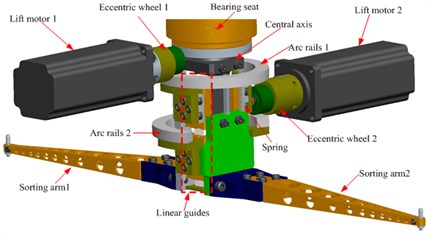
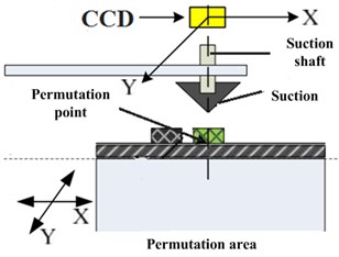
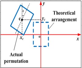
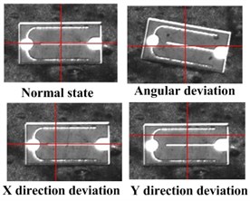
Fig. 1a) Sorting arm system model, b) chips arrangement structure, c) arrangement state, d) error schematic
a)
b)
c)
d)
In the experiment, the arrangement error of chip picking and placement was detected by image vision analysis method. The experimental device was high-speed camera (Model: GigaView). The shooting rate was set to 532 fps, and the resolution was 1280×1024. The experimental conditions are shown in Table 1.
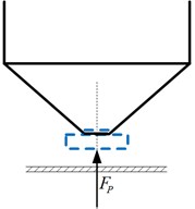
Fig. 1(a) presents the sorting arm, the main movement is 180° reciprocating rotation of the movement, which is driven by control motor. The move up and down movement is driven by two lifting motor through the eccentric wheel, the arc guide, the spring and the linear guide respectively. The arrangement of two chips can be completed within one revolution period. In the process of chip picking and placement, the positioning process of the chip is shown in Fig. 1(b), the end of sorting arm picks up the chip and rotates it over the top of the arrangement area, then drop the chip. The positioning accuracy of the chip is determined by the image identification of the CCD camera mounted at the top of the permutation area. Set the fixed CCD vision center as the target point. If there is no movement error and sorting arm structure’s vibration, the center point of the placement chip is overlapped with that target point. Therefore, the arrangement error model of placing chip by sorting arm can be established based on the fixed CCD visual coordinate system, as shown in Fig. 1(c). It is shown that the error that the deviation from center position to CCD visual center is arrangement error and the error is direction error and direction error respectively. In addition, considering the angle deflection of the chip body in placement process, the angle of deflection between the symmetric long axis and he direction is defined as the deviation of . Fig. 1(d) shows the placement error’s representation form of various chips based on fixed CCD visual coordinate system.
According to the definition of the placement error of the chip we can know that the -direction error, the -direction error and the -direction error of chips’ placement are related to the movement error of the sorting arm itself, the vibration of the sorting arm structure in all directions and the twisting vibration.
Table 1Experimental parameters
Project | Parameter |
High speed camera | SVSI GIGAVIEW 40173 |
Shooting rate | 1000 fps |
Shooting resolution | 720×480 |
Chip size | 12mil×28 mil |
Tip diameter | 75 μm |
Suction diameter | 200 μm |
2.1. Influence of sorting arm vibration in rotation direction on the arrangement error of the chip.
The sorting arm appears transverse vibration in the process of picking up and placing the chip, because of the twisting vibration of the sorting arm. The transverse vibration of the sorting arm can produce the fluctuation of sorting corner, and the fluctuation of the sorting arm will directly lead to the placement error of the chip. The sorting arm is used in the form of double sorting arm, which are symmetrical, so the two sorting arms’ angle fluctuations have the same effect on the analysis of chip arrangement errors. Therefore, one sorting arm is selected for analysis. Fig. 2 is the schematic of chip placement error which is caused by the transverse angle fluctuations of the sorting arm.
The arrangement area and the supply area are two independent fixed areas, so there will be a position deviation of the coordinate system that is set in the arrangement area and the supply area. In the actual operation process of the sorting arm, there is a certain angle between the two-sorting arms due to the manufacturing error. In Fig. 2, the sorting arm and are the angle of the -axis in the relative arrangement area and the supply area after the actual assembly of the double sorting arm. When the sorting arm is at the top of the -axis of the coordinate system in two areas, the direction is defined as the positive direction according to the motion characteristics. When the sorting arm is at the bottom of the -axis of the coordinate system in two areas, the direction is defined as the negative direction according to the motion characteristics. The angle size is determined by the three points shown in Fig. 2.
Fig. 2The schematic diagram of angle error of sorting arm
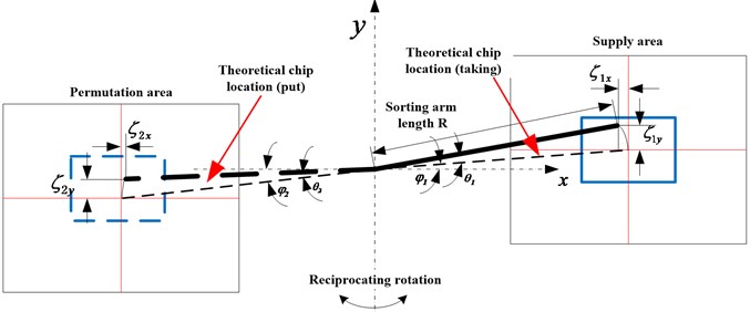
During the placement and picking of the chip, sorting arm movement will introduce the angle fluctuation. The actual sorting arm’s angle error is defined as , . There is a positive and negative direction on the transverse vibration of sorting arm, the positive direction of the angle error is set as the direction which the base position is consistent with the movement direction of the sorting arm and on the contrary is negative direction. In the coordinate system, the starting offset , , , are defined as the offset from the arrangement area and the supply area to the set dot (CCD camera center) respectively. is the effective arm length of the sorting arm. Based on the geometric relationship given in Fig. 2, the positioning error of the chip can be expressed as follows:
Setting , , as the chip placement error which is caused by the angle fluctuation of sorting arm. The -direction error, -direction error and chip angle deflection error introduced by this angle fluctuation can be expressed as follows:
It can be seen from the formula of placement error of the chip that is caused by the fluctuation of sorting arm angle. In the process of chip pickup and placement by sorting arm, the angle error of chip arrangement includes the angle error of the supply area and the angle error of the arrangement area, which is the sum of the two. Because the arrangement area and the supply area are two independent coordinate systems for chip picking and placement, so we can make the adjustments during component assembly. We can set 0. Since , are small, the two angles of deflection in Eq. (1) are satisfied: 0, then:
In the process of arm picking and placement, the sorting arm angle’s sorting arm error, and , caused by rotation direction vibration is generally smaller. So, we set them in a small range of fluctuations: , . The maximum value of chip arrangement error can be expressed as follows:
Therefore, the above error calculation formula can be used to analyze the influence of the transverse vibration of the sorting arm on the arrangement error of the chip. If the effective length of sorting arm is 197 mm, sorting arm vibration angle are: 10". In consideration of the relative small , , the linear error and angle error of chip arrangement error can be expressed as follows:
From the above calculation results, the linear error in the direction is not sensitive to the rotation angle of the sorting arm, which can be ignored. While the direction is sensitive to the rotation angle of the sorting arm, and according to the calculation, we select the angle fluctuation value. In the -direction, the linear error value is quite large, which is close to the sorting precision index of the chip array. Therefore, the Angle fluctuation of sorting arm rotation direction should be suppressed as far as possible in the process of arm picking and placement. Another factor affecting the linear positioning error of sorting arm -direction is the length of sorting arm. The amplification of linear positioning error in -direction is positively correlated with . Therefore, the short sorting arm length value should be selected in the precondition of keeping chip sorting function.
After adjustment of the assembly stage, the double sorting arms generally can be considered that the two sorting arms are fully fixed. Therefore, the above analysis shows that the error of between the two sorting arms picking and placing chip is negatively correlated. When the maximum error of chip placement by one arm appears, chip placement of the other arm has the minimal error.
2.2. Influence of sorting arm vibration in ascending and descending direction on the arrangement error of the chips.
In the process of arm picking and placement of chips, the sorting arm movement and thimble movement are not directly involved in the transmission of the error items. However, the vibration of the sorting arm structure will affect the picking chips’ effect of the nozzle at the end of the sorting arm. The vibration of the sorting arm during the operation of the arm will cause the end of the sorting arm to deviate from the normal working state. Then the power for drawing chip is too small, which causes the chips’ failure capture or offset. Therefore, when the chip picking state is unstable, it is easy to lose chips, or when placing the chip, the error of the array error is too large.
In the process of chip stripping, the adsorption capacity of the nozzle to the chip is generated by vacuum. The adsorption force can be determined by vacuum negative pressure () and the actual contact area () of the nozzle and the chip. It can be expressed as .
There are two main factors that affect the process of chip picking chip:
(i) The chip adsorption power of nozzle is too small, which is caused by the gas path factor of the system itself, for example, the pipeline’s vacuum negative pressure does not meet the requirements. The operation structure vibration’s of sorting arm has no influence on this factor. The reason is that the vacuum pump in the working process cannot provide enough pressure, or windpipe is broken, nozzle is broken etc.
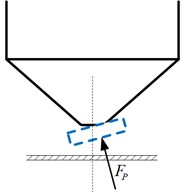
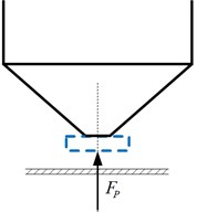
(ii) The actual contact area between the nozzle and chip is too small. The influence factors are related to the sorting arm structure’s running vibration in the process of chip’s pickup and placement. There are three situations in which the sorting arm vibration affects the adsorption chip: In the process of chip picking and placement, if the deviation between nozzle, at the end of the sorting arm, and center is too large, as shown in Fig. 3(a). The deviation of suction’s rise and fall is too large, as shown in Fig. 3(b). The vibration frequency of the nozzle is too large, as shown in Fig. 3(c).
Fig. 3Schematic diagram of small contact area between nozzle and chip: a) the deviation between nozzle and center is too large, b) the deviation of suction’s rise and fall is too large, c) the high-frequency vibration of the nozzle is too large
a)
b)
c)
3. Vibration suppression mode of sorting arm structure in high-frequency reciprocating motion
3.1. Vibration suppression mode based on the method of flexible acceleration and deceleration
In the process of arm picking and placement of chips, there is a great difference in the dynamics of the sorting arm between operation and the static situation. The response characteristic of sorting arm vibration is determined by the sorting arm’s working characteristic. In the process of sorting arm high frequency reciprocating operation, the start-stop impact of sorting arm is significantly related to the response value of its high frequency and low frequency band. And the peak of the low frequency response spectrum of the sorting arm is linearly increasing with the working frequency. Therefore, the impact control of sorting arm operation is an important part to suppress the vibration of sorting arm.
For the high frequency reciprocating operation of sorting arm, the quick positioning requirement will introduce a large inertial impact in the picking and placement stages. The inertia impact of the operation has significant influence on the high and low frequency response. This section adopts the method of flexible acceleration and deceleration design of motion instruction to reduce the inertia impact which introduced by the high frequency operation.
The mechanical part of the sorting arm is composed of the coupling, bearing and the sorting arm. In the sorting arm, the block diagram of resonant system is shown in Fig. 4 [37]. The rotor inertia of the motor is defined as , the inertia of the coupling is , the whole load elastic coefficient is , the torque of the connector is , the system’s transfer coefficient is , and set the load torque as 0.
From system block diagram, we can know the angular velocity transfer function of current input to motor output shaft is:
Fig. 4The resonant system of sorting arm
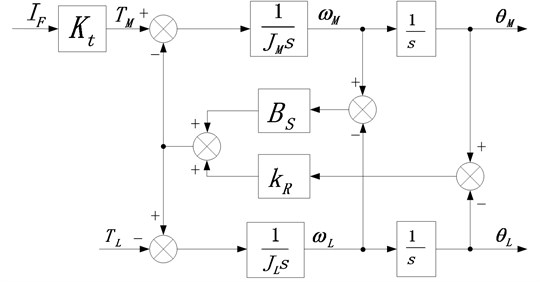
In Eq. (7), , and are the resonant angular frequency, the anti-resonant angular frequency and system angular frequency, respectively. is the torque coefficient. Setting the inertia ratio as /, then getting Eq. (8):
It can be seen that the smaller inertia ratio or the greater stiffness, the greater resonance angle frequency and anti-resonance angle frequency, and the less mechanical resonance. As shown in Fig. 5, the inertia ratio is shown in the Bode plot.
Fig. 5The Bode plot with different inertia ratios
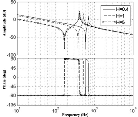
It can be seen that the larger inertia ratio, the lower resonance frequency, the easier mechanical vibration. In order to achieve high-bandwidth control of the servo loop, the inertia ratio is not too large. In addition, increasing the elastic coefficient can increase the resonance frequency, so it is also necessary to ensure the stiffness of the load. Therefore, in order to control the sorting arm at high-speed and high-precision, it is necessary to carry out a lightweight design and increase the stiffness of the load.
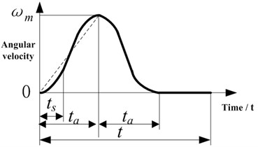
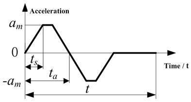
Because the high and low frequency’s vibration of the sorting arm structure is related to the high-frequency reciprocating impact of sorting arm, the high acceleration and deceleration of the rotating reciprocating motion which introduce the inertia impact of the part will cause the vibration of the multi-mode high and low frequency of the sorting arm structure. In order to reduce the inertia impact excitation introduced by reciprocating operation, the operation speed instruction adopts s-type acceleration and deceleration design scheme so that can reduce the inertia impact of reciprocating operation process of sorting arm structure. The s-type curve function is shown in Eq. (9), and the acceleration of each stage () is shown in Eq. (10):
According to the S-type acceleration and deceleration mode in Fig. 6, the sorting arm speed’s contour curve is designed. So, the acceleration can be sustained throughout the movement and there is no shock caused by acceleration mutations, besides, the acceleration changes slowly in starting and stopping segments. Reduce the acceleration of stop and improve the positioning accuracy.
Fig. 6The S-type velocity profile curve: a) angular velocity, b) acceleration
a)
b)
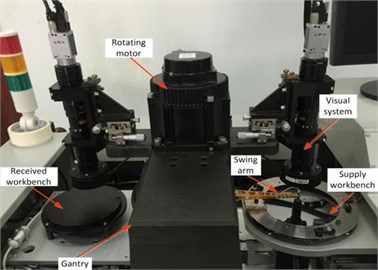
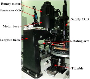
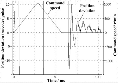
Fig. 7 is the experimental platform system of sorting arm high-speed motion control. The system completes the setting of movement control card, and controls servo motor to drive sorting arm mechanism’s reciprocating operation, at the same time, the control displacement and velocity are extracted. The rated power of the motor is 1.3 kw, its rated speed is 1500 r/min, the rotor's inertia moment is 19.9×10⁻⁴kg·m2, the resistance is 0.26 , the inductance is 4.01 mH, the resolution of shaft encoder is 20. The motion sequence of sorting arm is set to 55 ms (including stop 45 ms), 180° reciprocating motion.
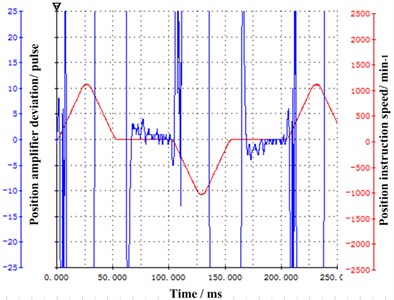
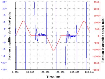
During the control of sorting arm reciprocating motion, in order to realize high system response speed and enhance system anti-interference ability, the speed loop gain parameters and position loop gain parameters are improved in servo control, at the same time, we reduce the time constant of speed ring integration. In the experimental analysis of speed loop control mode, the speed loop PI mode and IP mode are selected respectively. According to the set requirements of positioning error, the test results are shown in Fig. 8. From the figure, the speed ring IP control mode can be realized without overshoot, the impact of corresponding introduction is small and the influence on system’s time stability is small, the difference in the two ways is only one millisecond. In the error fluctuation of sorting arm, the speed loop IP control mode’s error fluctuation is approximately 2 pulses longer than the PI mode. The above experiments show that in the adjustment process, the operation process of the sorting arm is easy to become unstable and vibrate because of mechanical resonance and system delay.
Fig. 7a) LED chip sorting machine, b) high-speed positioning experiment platform
a)
b)
Fig. 8The final accuracy curve of speed loop control: a) PI control, b) IP control
a)
b)
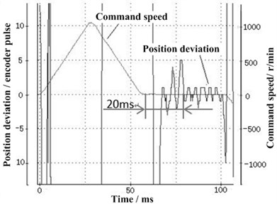
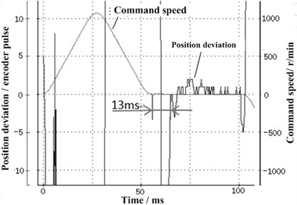
Fig. 9The positioning effect between S-type and non-S-type velocity contour curves: a) non-S-type curve, b) S-type curve
a)
b)
Under the setting of S-type velocity curve, the component running shock experiment gives the S-type velocity instruction curve and under the running of non-S-type speed instruction curve, gives the sorting arm vibration response. Fig. 9 is the results of experimental analysis. It can be seen from the figure that the setting time of sorting arm operation process with the non-S-type velocity contour curve is 20 ms. The setting time of the sorting arm operation process with S-speed contour curve is significantly reduced, just is 13 ms. Obviously, the S-type design of the sorting arm control process can effectively suppress the vibration of sorting arm during the operation of the sorting arm, and also improve the positioning speed of the sorting arm.
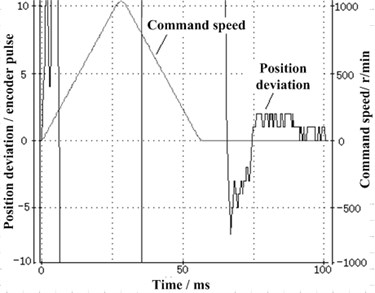
Considering the influence of high frequency components introduced by sorting arm operation control on the vibration of sorting arm structure, the low pass filter is used to suppress high frequency input. The positioning accuracy of the motor under different filtering time constant is shown in Fig. 10. As shown in the figure, when a smaller filter time parameter is set, the filter time is changed from 0.16 ms to 0.66 ms, the overshoot of sorting arm is significantly reduced and the corresponding sorting arm running vibration will be effectively suppressed. The positioning accuracy of sorting arm also improves, and the stabilization time is shortened.
Fig. 10The time constant of different low-passed filter: a) the filter time constant is 0.16 ms, b) the filter time constant is 0.66ms
a)
b)
3.2. Vibration suppression mode based on the method of variable timing sequence
The vibration, which is caused by the variable structure, is determined by the timing sequence in the operation process. The variable structure impact is introduced because of the sequential segments. Therefore, the sorting arm vibration introduced in the form of structure can be adjusted by the timing sequence of the moving parts. A certain stable period of time is reserved in the control of the time sequence, then the vibration response in the upper and the rotation direction can be suppressed.
In the process of sorting arm high frequency reciprocating operation, the inertia impact of the sorting arm is introduced to the sorting arm structure’s vibration, the descending stroke is related to the sorting arm vibration response. The technological parameters are closely related to the accuracy rate of chip sorting and influence the efficiency of chip sorting. In order to ensure the success rate of chip sorting, it is necessary to find out the most suitable technological parameters and improve the accuracy of chip sorting as far as possible, so as to reduce the influence of sorting arm structure’s vibration.
In the setting index of sorting arm mechanism, the movement time 58 ms and the sorting arm lifting time 20 ms, based on them, the acceleration curve of the motor is designed and the experiment of chip sorting is performed. The chip size of the experiment is 12 mil×24 mil, the diameter of nozzle hole is 200 μm.
Table 2 is the experimental results of the height of the nozzle extruding chip. Under the condition of not changing the other parameters, the different pressure height is adjusted and the result of different chip is obtained. It can be seen from the table that when the 50 μm, the loss rate is higher, when the 50 μm, the loss rate is lower. The height above 50μm can be used as the height parameter of nozzle. However, the larger the suction pressure, the greater the vibration response of the sorting arm. Therefore, we should to take the smaller value as far as possible in the premise of ensuring the sorting of loss rate, so we choose 50 μm.
Table 2Optimization of the height of the nozzle pressing chip
Groups | [μm] | [μm] | [μm] | [ms] | [ms] | [ms] | Sorting number | Sorting speed [ms/ pieces] | Missed number | Lost rate [%] |
1 | 0 | 480 | 250 | 0 | 2 | 0 | 384 | 104 | 5 | 1.30 |
2 | 30 | 480 | 250 | 0 | 2 | 0 | 403 | 104 | 4 | 0.99 |
3 | 50 | 480 | 250 | 0 | 2 | 0 | 642 | 104 | 0 | 0 |
4 | 80 | 480 | 250 | 0 | 2 | 0 | 745 | 104 | 0 | 0 |
5 | 100 | 480 | 250 | 0 | 2 | 0 | 638 | 104 | 0 | 0 |
The height of the suction lifts higher, and then the vibration of the sorting arm in the process is more difficult for picking up the chip. According to the results of Table 3, 250 μm is chosen.
Table 3Optimization of the lifting height of the nozzle
Groups | [μm] | [μm] | [μm] | [ms] | [ms] | [ms] | Sorting number | Sorting speed [ms/ pieces] | Missed number | Lost rate [%] |
1 | 50 | 480 | 200 | 0 | 2 | 0 | 511 | 104 | 0 | 0 |
2 | 50 | 480 | 250 | 0 | 2 | 0 | 642 | 104 | 0 | 0 |
3 | 50 | 480 | 300 | 0 | 2 | 0 | 515 | 104 | 2 | 0.39 |
4 | 50 | 480 | 350 | 0 | 2 | 0 | 548 | 104 | 2 | 0.36 |
5 | 50 | 480 | 400 | 0 | 2 | 0 | 522 | 104 | 5 | 0.96 |
The stability time is the time when the sorting arm reaches the specified position. The longer the time, the higher the positioning accuracy, but the lower the separation efficiency. From Table 4, that lengthening the stop time has no obvious effect on the lost rate of chip sorting. This is because the sorting arm reaches the specified position and begins to go down, the drop time is 20 ms. During the 20 ms, the vibration of the sorting arm’s rotation direction will attenuate significantly. Therefore, the stop time has no obvious effect on the attenuation of the sorting arm vibration, then 0 ms is chosen.
Table 4Optimization of stability time when the sorting arm reaches the specified position
Groups | [μm] | [μm] | [μm] | [ms] | [ms] | [ms] | Sorting number | Sorting speed [ms/ pieces] | Missed number | Lost rate [%] |
1 | 50 | 480 | 250 | 0 | 2 | 0 | 642 | 104 | 0 | 0 |
2 | 50 | 480 | 250 | 2 | 2 | 0 | 480 | 105 | 0 | 0 |
3 | 50 | 480 | 250 | 4 | 2 | 0 | 542 | 108 | 3 | 0.55 |
4 | 50 | 480 | 250 | 6 | 2 | 0 | 501 | 112 | 0 | 0 |
The dwell time of picking up chip is the time of the nozzle to press down the chip, the longer the time, the better the vibration attenuation of the arm lifting direction, but also reduces the efficiency of chip sorting. From Table 5, the selection of 2 ms can meet the requirements.
Table 5Optimization of the stabilization time of the nozzle caught chip
Groups | [ms] | [ms] | [ms] | [ms] | [ms] | [ms] | Sorting number | Sorting speed [ms/ pieces] | Missed number | Lost rate [%] |
1 | 50 | 480 | 250 | 0 | 0 | 0 | 422 | 100 | 4 | 0.95 |
2 | 50 | 480 | 250 | 0 | 2 | 0 | 642 | 104 | 0 | 0 |
3 | 50 | 480 | 250 | 0 | 4 | 0 | 482 | 107 | 1 | 0.21 |
4 | 50 | 480 | 250 | 0 | 6 | 0 | 512 | 112 | 0 | 0 |
4. The experimental verification of vibration suppression of sorting arm
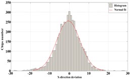
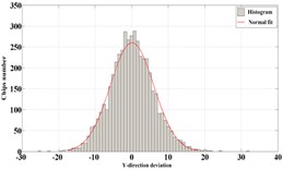
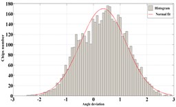
This section carries out experiments to verify the method of vibration suppression which is proposed in the section 3. By the picking and placement of chips. Analysis of chip arrangement error to verify the effectiveness of the vibration suppression method. The number of chips used in the experiment was about 5,000. Three results of the tests were shown below:
Test 1: The statistical results are shown in Table 6. The distribution curve of arrangement error is shown in Fig. 11(a), 11(b), 11(c).
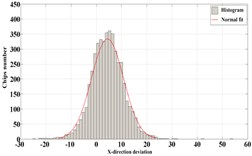
Test 2: The statistical results are shown in Table 6. The distribution curve of arrangement error is shown in Fig. 11(d), 11(e), 11(f).
Test 3: The statistical results are shown in Table 6. The distribution curve of arrangement error is shown in Fig. 11(g), 11(h), 11(i).
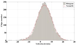
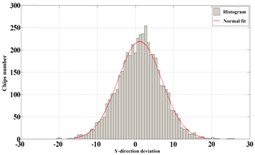
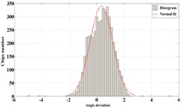
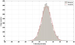
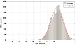
Fig. 11Distribution of error in each direction: a) X-direction error of Test 1, b) Y-direction error of Test 1, c) angle error of Test 1, d) X-direction error of Test 2, e) Y-direction error of Test 2, f) angle error of Test 2, g) X-direction error of Test 3, h) Y-direction error of Test 3, i) angle error of Test 3
a)
b)
c)
d)
e)
f)
g)
h)
i)
From the above three groups of tests, the following conclusion is obtained:
(i) The linear error of the -direction, the -direction and the angle-direction are all typical normal distribution, the angle error of the chip arrangement shows the furcation before vibration suppression. After the vibration suppression, the angle error of chip arrangement did not appear furcation. The experimental results show that the precision of the sorting arm can be improved obviously after the vibration suppression.
(ii) After the vibration suppression, the maximum single sorting speed of the sorting system is about 104 ms, closes to the design requirement of 100 ms and the qualified rate of sorting is above 99.3 %, which meet the market demand basically.
Table 6The statistical results of tests
Items | Test 1 | Test 2 | Test 3 |
Number of sorted chips | 4708 | 4697 | 4693 |
The maximum sorting speed | 104 ms/piece | 104 ms/piece | 104 ms/piece |
The average sorting speed | 140 ms/ piece | 140 ms/ piece | 140 ms/ piece |
The rate of sorting | 99.70 % | 99.73 % | 99.36 % |
-direction error’s standard deviation | 6.48 | 6.00 | 6.26 |
-direction error’s standard deviation | 5.73 | 5.95 | 7.34 |
Angle-direction error’s standard deviation | 0.81 | 0.85 | 0.85 |
5. Conclusions
The paper takes the sorting arm of LED chip sorting machine as the studied object. The relationship between the vibration of the sorting arm and the positioning error of the chip are obtained. And the correlation between the sorting arm structure’s vibration and the working precision of the separator are pointed out. The operation control of sorting arm is optimized based on the dynamics of the sorting arm. The operation parameters are optimized from the time sequence setting, so that to shorten the vibration attenuation time of the sorting arm for suppress vibration and provide efficiency. The incentives, which are introduced by variable structure and by the operation, can be effectively controlled. The array accuracy of chips and working efficiency of chip sorting machine are improved.
References
-
Pelka D. G., Patel K. An overview of LED applications for general illumination. Design of Efficient Illumination Systems, Vol. 5186, 2003, p. 15-27.
-
Shiang W J. Application of simulation to the scheduling problem for a LED sorting system. International Conference on Machine Learning and Cybernetics, Vol. 5, 2009, p. 2875-2879.
-
Oakley C. M., Cannon R. H. End-point control of a two-link manipulator with a very flexible forearm: issues and experiments. American Control Conference, 1989, p. 1381-1388.
-
Cannon R. H., Schmitz E. Initial experiments on the end-point control of a flexible one-link robot. The International Journal of Robotics Research, Vol. 3, Issue 3, 1984, p. 62-75.
-
Wang D., Vidyasagar M. Transfer functions for a single flexible link. IEEE International Conference on Robotics and Automation, 1989, p. 1042-1043.
-
Asada H., Z. D. M., Tokumaru H. Inverse dynamics of flexible robot arms: Modeling and computation for trajectory control. Journal of Dynamic Systems, Measurement and Control, Vol. 112, 1990, p. 177-185.
-
Chedmail P., Aoustin Y. Modeling and control of flexible robot. International Journal Numerical Methods Engineering, Vol. 32, 1991, p. 1595-1619.
-
Rovner D. M., Cannon R. H. Experiment toward on-line identification and control of a very flexible one-link manipulator. International Journal Robot Research, Vol. 6, Issue 4, 1987, p. 3-19.
-
Song T. T. Active Structural Control: Theory and Practice. Longman Scientific and Technical, 1990.
-
Ferri A. A. Friction damping and isolation systems. Journal of Dynamics Systems, Measurement and Control, Vol. 117, Issue 2, 1995, p. 196-206.
-
Ferri A. A., Heck B. S. analytical investigation of damping enhancement using active and passive structural joints. Journal of Guidance, Control, and Dynamics, Vol. 15, Issue 5, 1992, p. 1258-1264.
-
Simonian S. S. Particle damping applications. 45th AIAA/ASME/ASCE/AHS/ ASC Structures, Structural Dynamics and Materials Conference, California, 2004, p. 19-22.
-
Saluena C., Poschel T., Sergei E., Esipov S. E. Dissipative properties of vibrated granular materials. Physical Review Letters, Vol. 59, Issue 4, 1999, p. 4422-4425.
-
Taguchi Y. New origin of a convective motion: elastically induced convection in granular materials. Physical Review Letters, Vol. 69, Issue 9, 1992, p. 1367-1370.
-
Miles R. N. Beam dampers for skin vibration and noise reduction in the 747. Vibration Damping Workshop Proceedings, 1984, p. 1-18.
-
Friend R. D., King V. K. Particle Impact Damping Journal. Journal of Sound and Vibration, Vol. 223, Issue 1, 2000, p. 93-118.
-
Bai X., Keer L., Wang Q. Investigation of particle damping mechanism via particle dynamics simulations. Granular Matter, Vol. 11, Issue 6, 2009, p. 417-429.
-
Chan K. W., Liao W. H., Wang M. Y. Experimental studies for particle damping on a bond arm. Journal of Vibration and Control, Vol. 12, 2006, p. 297-312.
-
Younkin George Modeling machine tool feed servo drives using simulation techniques to predict performance. Conference Record of the IEEE Industry Applications Society Annual Meeting, 1989, p. 1699-1706.
-
Ma Ping, Liao Chengxiang, Chen Zhenhui, Chen Aimin Dynamic response of the linear motor feed drives with magneto- rheological fluid damper. International Conference on Mechanic Automation and Control Engineering, 2010, p. 3072-3077.
-
Lu Yanhao Grain Picking Equipment. China, 201020237411, 2011.
-
Wang Si Technology Co., Ltd. Fully Automated Sorter-MP76A Manual. Simplified Chinese Version V2.0, 2011.
-
Yi Wenjun GaN LED Chip Automatic Sorter Research and Development. Master’s Thesis, Beijing University of Science and Technology, 2007.
-
Zhu Xin Yu LED Chip Sorting Key Technology Research. Ph.D. Thesis, Beijing University of Technology, 2007.
-
Wu Tao, Li Bin, Wang Longwen, et al. Analysis on mechanisms and performance of on-line angle correction in LED die sorting. Proceedings of the International Conference. on Mathematics and Its Applications, 210, p. 282-287.
-
Wu Tao, Li Bin, Wang Longwen Study on auto-path planning according to grade priority for sorting dies. International Conference on Machine Learning and Computing, 2010, p. 1590-1595.
-
Ao Wu, Bin Li, Longwen Wang, et al. Study on Parallel Schedling of LED Dies Measurement and Grading. International Conference on Electronic Packaging Technology and High Density Packaging, 2010, p. 1426-1430.
-
Cai Libin LED Chip Sorter High-Speed Moving Parts Design and Implementation. Master’s Thesis, Huazhong University of Science and Technology, 2009.
-
Wang Yingjun LED Chip Sorting Institutions Elastic Dynamic Response Suppression. Master’s Thesis, Huazhong University of Science and Technology, 2009.
-
Wang Chengkai LED Chip High-Speed Sorting Machine Sorting Arm Electromechanical Simulation and Experimental Verification. Master’s Thesis, Huazhong University of Science and Technology, 2011.
-
Chen Zhenxing High-Speed LED Chip Sorting Arm Vibration Suppression Technology Research. Master’s Thesis, Huazhong University of Science and Technology, 2012.
-
Jie Ouyang LED Chip High-Speed Sorting System Control Technology and Sorting Process. Master’s Thesis, Huazhong University of Science and Technology, 2013.
-
Luo Bing, Zhang Zhenzi Autonomous docking based on visual error feedback research. Heilongjiang Automation Technology and Application, Vol. 4, 1997, p. 35-38.
-
Liu Wenchao Computer Quilting Machine Motion Control System. Master’s Degree Thesis, Qingdao University of Science and Technology, 2006.
-
Jia Dongyong Fetching operation of humanoid robot based on visual feed-forward and visual feedback. Journal of Beijing Institute of Technology, Vol. 29, Issue 11, 2009, p. 983-987.
-
Hu Xuxiao, Tai Xianqing, Yang Keji Synchronization control of stepping scanning lithography and wafer deformation error compensation technology. China Mechanical Engineering, Vol. 15, Issue 3, 2004, p. 192-195.
-
George Ellis, Gao Zhiqiang Cures for low-frequency mechanical resonance in industrial servo system. IEEE Industry Applications Society Annual Meeting, Vol. 1, 2001, p. 252-257.
About this article

The research is supported by the National Natural Science Foundation of China under Grant No. 51775212 and 51505084. The authors are grateful to other participants of the project for their cooperation.
