Abstract
Robotic arms are frequently utilized in contemporary industrial production since they offer great qualities like high precision and low mass. How to minimize robotic arm tremors in order to maximize their control effect has emerged as one of the most critical issues to be resolved with the continued development of industrial intelligence. The study uses a combination of PID control and an artificial fish swarm technique to optimize the parameters and confirm the simulation control effect based on the kinematic analysis of a six-degree-of-freedom (Six-DOF) modular robotic arm. The findings demonstrated that the suggested fusion approach converges to zero in 80 iterations and has a recall of 0.893 and 0.785 at an accuracy of 0.8 and 0.9, respectively. The robotic arm control system’s average control effect is 42.96 %, which is a respectable control performance. In the second and third studies, the fusion approach stabilized actuator end tremor suppression after 0.01 s and 0.0001 s, respectively. It shows that the technique can effectively suppress robotic arm bearing tremor and has high flexibility for robotic arm tremor suppression, which offers trustworthy technological support for improving the motion control system of industrial robots.
1. Introduction
Intelligent robots are gradually being promoted and used in many industries, such as automatic assembly and precision machining, as a result of the ongoing acceleration of the industrial innovation process and the quick expansion of high-tech industries. Robotic arms are a crucial part of intelligent robots that are widely utilized in industrial production. They have had a significant impact on the advancement of human history as a whole. Modern new robotic arms are significantly more complicated than older styles of industrial robotic arms, and they also have a greater level of precision in their motion control systems [1-2]. As the core equipment of modern intelligent manufacturing systems, the control system of the six-degree-of-freedom (Six-DOF) robotic arm will directly affect production efficiency and production cost, which is the key direction of attention in this field. In the control system of the Six-DOF robotic arm, bearing chatter suppression is a real problem that cannot be avoided. There are currently two types of vibration suppression: passive control and active control. Passive control responds to the vibration problem through the change of structural vibration characteristics and the increase in vibration energy consumption of the peripheral structure without external energy intervention, with poor control effect and limited control capability [3-4]. Compared to passive control, active control combines external actuators with sensors to meet more demanding vibration requirements and is more widely used in modern robot control. Active control systems need to first analyse the dynamics and vibration characteristics of the object and then implement vibration control through sensors and control algorithms that can cope with a wide range of excitation vibration situations. However, given the current performance requirements of robotic arms, active control methods still face many shortcomings, such as low accuracy and low efficiency [5]. In hopes of further improving the vibration suppression effect, the study addresses the bearing vibration suppression problem of a Six-DOFmodular robotic arm and proposes a control method that combines an artificial fish swarming algorithm (AFSA) (i.e., a machine vision algorithm) with an optimized PID.
2. Related works
Robots with high accuracy and extended lifespans are essential for the growth of the manufacturing sector; hence, it’s essential to reduce robot arm vibrations. There has been a lot of study done to address this problem, and the findings are promising. Focusing on a dynamic model for the external vibration of a hydraulic track excavator, Hoang Q. D. et al. suggested a new controller design technique combining feedback linearisation with sliding film control. During experimentation, it was discovered that the operational link has more precise tracking performance. And the control system used in this way can effectively reduce the system’s vibration when supported by elastic [6]. A phase-based video measurement technique was developed by Peng C. et al. and used to measure the active vibration suppression system of a magnetically levitated rotor system. Using a high-speed camera to record the rotor system's vibration and a phase-based vibration extraction algorithm to extract the vibration characteristics and displacements, the procedure modelled the synchronous vibration and system dynamics brought on by rotor mass imbalance. The findings demonstrate that the suggested approach is efficient and workable while successfully controlling rotor system vibration [7]. The two-sided hybrid excitation ECD (ECD) was the solution that Sang N’s team suggested for the occurrence of vibration conditions in linear motor systems during high-speed operation. Throughout the procedure, an analytical model of the ECD was built, and the model was validated using finite element analysis. The findings demonstrated that the peak amplitude and stability duration of the revised system’s vibration position error were successfully decreased by 68.88 % and 33.33 %, respectively [8]. For the magnetic levitation control force matrix rotor system’s vibration suppression effect, Li J. et al. suggested an improved adaptive frequency estimation (IAFE) method. The method uses sensing signal characteristics to perform adaptive control of the rotor speed, efficiently regulating the current generated by the system while altering the phase shift angle at various frequencies to ensure system stability. The outcomes demonstrate the method's great viability and potential for vibration suppression [9].
Lin C. J. et al. suggested a support vector machine based on the artificial fish swarm technique for identifying ball bearing problems. In hopes of creating a set of identification models for failure prediction using a signal processing technique, the tests were conducted on a fault diagnosis simulation platform for four different types of ball bearings. The outcomes demonstrated that the classifier parameters acquired using this methodology were ideal and had a high level of fault classification accuracy [10]. To increase the operational effectiveness of software testing, Xing Y. et al. proposed employing an AFSA to solve the technical challenge of test case prioritisation (TCP). The artificial fish swarm coding technique was created in conjunction with the interactions between the test cases during the studies. The findings demonstrate that the AFSA performs better than competing methods for both single- and multi-objective test set challenges while also greatly increasing software testing effectiveness [11]. To address the warp knitting fabric crossbar problem of a multi-speed electronic warp feeding system, Ren W. et al. suggest a design solution for a fully digital intelligent multi-speed electronic system. The process uses a fuzzy PID control technique to modify the hardware structure and software in accordance with the features of the system in order to achieve stable multi-speed electronic warp feeding. Finally, the efficiency of the approach is confirmed by simulation [12]. The redundant movement of the robot end-effector during the positioning task is addressed by Krishnan and Sankar sliding's mode controller (SMC). The robot motion is tracked and image features are retrieved, and the success of the approach is determined by feature trajectory testing. The findings demonstrated the method's high stability, ability to track the robot controller's vibration in real-time, and viability [13]. A PID-PSS method based on control constraints was created by Lakshmi et al. And colleagues to modify the operational stability of the power system stabiliser (PSS). The method was tested using a single machine infinite bus (OMIB) power system on a variety of test cases, and the results revealed that the proposed approach could suppress both static and dynamic mechanical vibrations and that the improved controller’s control effect was noticeably superior to that of the conventional controller [14].
The AFSA is currently utilised extensively across various industries as a result of the study mentioned above by domestic and foreign academics. While a few studies have merged AFSAs with PID active control techniques to solve the robot arm tremor suppression problem, the majority of these works concentrate on the analysis of rotor systems or other mechanical vibration suppression. As a result, a Six-DOF robotic arm tremor suppression system is suggested based on a combination of machine vision and PID technology. This system is projected to successfully suppress vibrations during robotic arm tasks and increase the effectiveness and lifespan of the robotic arm.
3. Design of a bearing vibration suppression method for a six-DOF robotic arm
3.1. Kinematic analysis of a six-DOF modular robotic arm
The study focuses on a modular robotic arm with six-DOF that has varied lengths of motion in each of its rotating joints. Different-sized modular joints are assigned in accordance with the function of power and load factors, taking into account the arm's range of motion. The first and fifth joint axes of the Six-DOFrobot arm used in the study are in the vertical direction, while the second, third, fourth, and sixth joint axes are in the horizontal direction. An axis-vertical linkage, an axis-parallel linkage, and six rotatable joints typically make up a Six-DOFrobot arm. These jointed bars are each joined to a maximum of two other jointed bars [15-16]. There are equivalent D-H representations for the various rotating joint coordinate systems due to the various properties of the particular axial joints. Table 1 lists the relevant D-H parameters.
Table 1Standard D-H parameters of 6 HF manipulator
Connecting rod serial number | Joint angle range | Scope | |||
1 | 90° | 0 | (90°) | 511 | –180°~180° |
2 | 0° | 350 | (90°) | 521 | 0°~180° |
3 | 0° | 290 | (0°) | 17 | –90°~180° |
4 | 90° | 0 | (90°) | 0 | 0°~180° |
5 | -90° | 0 | (0°) | 344 | –180°~180° |
6 | 0° | 0 | (0°) | 0 | –180°~180° |
As shown in Table 1, each rod can be represented by a scale representation where represents the angle between the two axis joint links and indicates the length of the rod, which is the shortest distance between the two joint axes (i.e. the torsion angle of the rod). By measuring the distance and the angle between the two rods, the study establishes the link between their positions. After adopting the normal D-H coordinate system’s parameters, the six-DOF robotic arm’s coordinate system is established. Equation must be satisfied by the built-in D-H parametric technique Eq. (1):
and in Eq. (1) stand for the rotation matrix around the axial joint and the translation matrix along the axial motion, respectively. The distance along the axis between and is indicated by the symbol . indicates the rotation from to the corner between around the axis. stands for the separation between and along the axis. The angle of rotation from to is represented by , which denotes the orientation around the -axis. Eq. (2) is then used to calculate the rotation and translation matrices’ expressions:
stands for the position transformation matrix in Eq. (2). By adding the D-H data to the equation, the transformation matrix between the individual axis joints is obtained. The transformation connection between the end of the robot arm and the base of the robot arm is the product of the transformation matrix between each neighbouring link, as shown in Eq. (3):
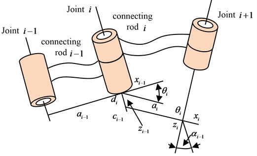
The transformation matrix between the coordinate system of the base of the robot arm and the matrix created by the combination of , , in Eq. (3) can be calculated by multiplying the matrices. The end-effector of the robot arm's end-effector is represented by the three-dimensional coordinates . The equations for the robotic arm’s forward motion can be determined using the D-H parametric technique, and if the rotation angle of the axis joint is known, it is possible to determine the position of the robotic arm end-effector with respect to the position of the coordinate system [17-18]. A kinematic model of the Six-DOFrobotic arm joint using the standard D-H parametric method is shown in Fig. 1.
Fig. 1D-H parameters modeling the joint movement of the robotic arm
The inverse kinematics of the robot arm is generated and explained using the coordinates and velocity of the robot hand after deriving the forward kinematics of the robot arm and acquiring all the joint angles. Eq. (4) can be created by multiplying the left side of Eq. (3) by a factor of and the right side by a factor of , using robot arm joint 1 as an example:
The inverse kinematic position transformation matrix is obtained by substituting the D-H parameters into equation; it is abbreviated and is displayed in Eq. (5):
The final expression for the corner of joint 1 is given in equation after Eq. (5)'s combination is solved for Eq. (6):
The expression for all joint angles can be produced in the same manner by applying the aforementioned equation, as demonstrated in Eq. (7):
where, . The positive and negative kinematic equations for a Six-DOF robot arm can be calculated more precisely with all of the aforementioned equations. Moreover, the motion trajectory of each joint may be readily determined when the trajectory of the robot arm’s end effector is known. To operate the arm quickly, the robot arm control system is given efficient kinematic settings.
3.2. Design of a six-DOF robotic arm oscillation control method based on visual measurement and optimized PID
The end of a Six-DOFrobotic arm is subject to severe jitter during operation, so the research is based on a kinematic analysis of the Six-DOFrobotic arm, with displacement measurements of the vibrations at the end of the arm and thus active control of the changes. The study uses real-time tremor displacement signals obtained from visual measurements as control inputs [19-20]. The control algorithm is used to output a control voltage to achieve tremor suppression in the robotic arm. To complete the experiment, the study first selects the PID control algorithm in active control, incorporating intelligent optimisation strategies for parameter optimisation and selection. In accordance to the definition of the control algorithm, the corresponding controller is composed of three parts, namely Proportional, Integral and Differential. The relationship between the output and the input of the system is shown in Eq. (8):
where, represents the input to the system and represents the output of the system. represents the proportional parameter, represents the integral time parameter and represents the differential time parameter. , and are all variables that can be regulated in the system. The transfer function of the system is shown in Eq. (9):
stands for the system transfer function in Eq. (9). Fig. 2 displays a schematic diagram of the PID control method.
Fig. 2PID control and application principle
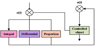
a) The PID control principle
b) The application of PID control to manipulator
Fig. 2(a) is the PID control principle; Fig. 2(b) is the Application of PID Control to Manipulator. Due to the increased usage of control technology, research can be focused on the choice of objects in various systems. To obtain control of the system, control experiments can be performed by choosing just one or two of the three components: proportional, integral, and differential (i.e., P, PI, PD control), or by altering the settings of the various control connections. The selection of parameters affects the efficacy of the control, and depending on that selection, the researcher can choose the sort of approach. The control system is classified into two categories: online adaptive and ideal parameter determination [21]. The offline approach, also known as the rectification method, typically relies on artificial empirical equations to determine the parameters (usually using the Ziegler-Nichol response curve method). The step response of the controlled item can be used to determine the system model. Eq. (10) contains the model’s parameters and expression:
stands for the system model in Eq. (10), , , and stand for the control parameters that were created by merging empirical equations. stands for the pure lag time, for the time constant, and for the model scale factor. The selection of the robotic arm end tremor data is then optimised using an intelligent optimization technique for visual measurement. The AFSA, an intelligent optimization technique based on a school of fish’s behaviour, is preferred. Fig. 3 depicts the algorithm’s implementation procedure.
The process begins by simulating the tremor at the end of the robotic arm as an artificial fish swimming. Assuming that the state at this point is and the corresponding sensing range is , if a new position state is observed within the sensing range at a certain moment, the state of the position is discriminated to observe whether it is better than the current moment state. If it is better than the current state, it will continue to swim in the direction of the observation and get a distance of . If it is not better than the current state, it will continue to search for another position until it satisfies the requirement to end the iteration. The expression of the above process is given in Eq. (11):
stands for a function with values between [0, 1] in Eq. (11) while stands for a movement step. Different states are denoted by , which stands for and , respectively. The work integrates the artificial fish swarm method with the PID control algorithm to produce the best PID controller for the six-DOF modular robotic arm tremor control system. In the artificial fish swarm experiment, the PID parameters are utilised as simulation parameters, and the simulation control effect is employed as the nutrient concentration, i.e., the degree of adaptation. After numerous iterations of optimization, the ideal state results are obtained. Fig. 4 depicts the particular optimisation procedure and the functioning of the simulation control system.
Fig. 3Implementation process of the artificial fish algorithm
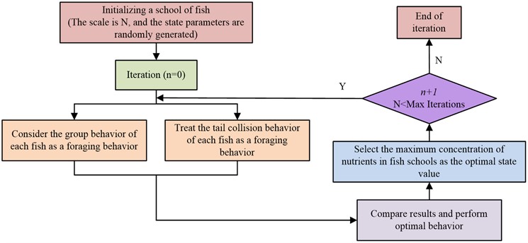
Fig. 4Control flow chart of fused artificial fish-PID technology
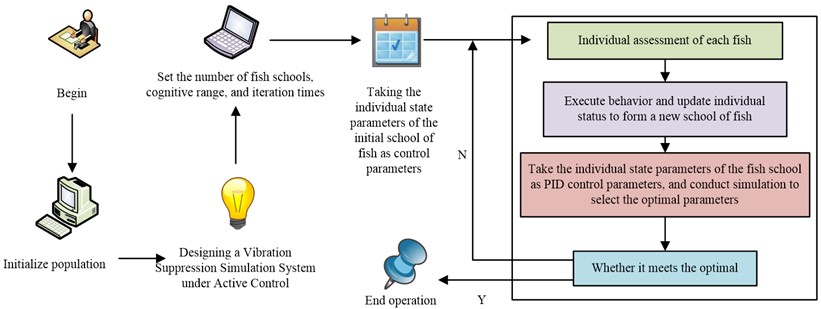
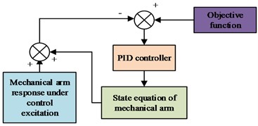
As shown in Fig. 4, the system typically includes a simulation model for a robotic arm, a PID controller, an objective function, and related parts. The general procedure is as follows: to induce a tremor response, the controlled item is exposed to the controller’s output. Where the controller receives feedback from the control error, which is the difference between the response function and the objective function, to create a closed loop. The Six-DOFrobot arm can be viewed as a cantilever in accordance with the structural model, which corresponds to the cantilever beam spatial state expression in Eq. (12):
In Eq. (12), represents the vibration displacement matrix, represents the input matrix, , , represents the modal stiffness, modal mass and modal damping of the mechanical arm cantilever beam and represents the force factor. Since the vibration control mode is the first stage mode, the stiffness, mass and damping of the first-order mode are assumed to be , , , and the expressions of the relevant parameters need to satisfy Eq. (13):
where, denotes the damping ratio and denotes the intrinsic frequency. And it can be noted that the equation of state of the robotic arm can be solved by using the structural damping ratio and the inherent frequency. The damping ratio and natural frequency can be extracted and solved using the frequency response method. The damping ratio solution is given in Eq. (14):
where, represents the frequency and this value has an effect on the magnitude of the output ratio. The final synthesis of the above gives the spatial equation of state of the robotic arm. The simulation test system is shown in Fig. 5.
Fig. 5Simulation system framework diagram
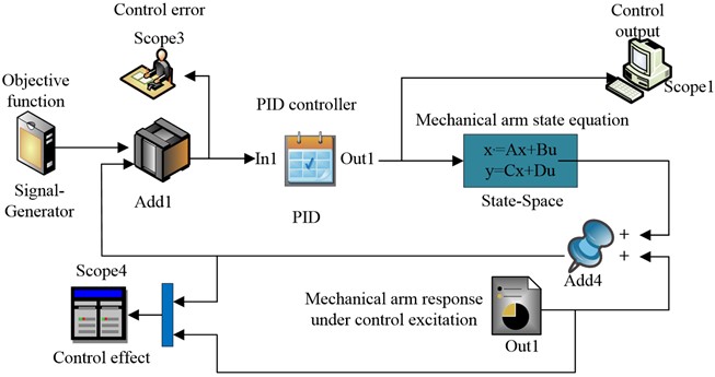
The spatial equation of state of the robotic arm in the simulation system of Fig. 6 has to be filled in according to the model equation, with taking the value range and being substituted in as a zero matrix. In addition, as the control objective of the study is to suppress the tremor of the robotic arm, the objective function is set to 0. The simulation system platform is constructed according to the study control scheme.
4. Performance analysis and application of six-DOF robotic arm bearing chatter suppression system based on artificial fish swarm optimized PID
4.1. Performance analysis of a Six-DOF robotic arm bearing chatter suppression system
In an effort to verify the effectiveness of the artificial fish swarm-PID control technique in a robotic arm-bearing tremor suppression system, the study began by testing the performance of the constructed system. The basic hardware environment setup for the experiments is presented in Table 1.
Table 2The experimental basic environmental parameters
Parameter variables | Parameter selection |
The overall implementation platform of the system | Simulink |
operating system | Windows10 |
Operating environment | MATLAB |
System PC side memory | 12G |
CPU dominant frequency | 2.62Hz |
GPU | RTX-2070 |
Central Processing Unit | i7-8700 |
data storage | MySQL data bank |
Data regression analysis platform | SPSS26.0 |
Firstly, Improved Ant Colony Algorithm (IACA) and Improved Convolutional Neural Networks (ICNN), which have the same experimental experience, were selected for performance comparison with the research algorithm. The number of iterations of each algorithm was set to 100 to ensure that the experiments were conducted in a fair and reasonable manner. The Cornell dataset and the Jacquard dataset were then selected to examine the performance metrics of the models, where the convergence variation of the algorithms is shown in Fig. 6.
Fig. 6Comparison of convergence changes for different algorithms
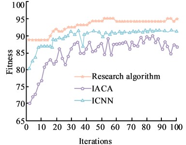
a) Cornell dataset
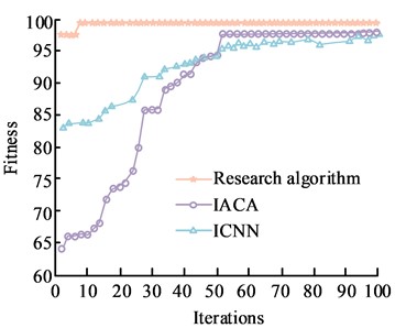
b) Jacquard data set
As can be noticed from Fig. 6, the values of the degree of adaptation under all three algorithm runs show a certain increase as the number of iterations increases. Fig. 6(a) shows the quiz of convergence on the Cornell dataset. With the iterations, the values of the degrees of adaptation of the two algorithms, IACA and ICNC, show a fluctuating trend of zigzag changes and do not have stable values. In contrast, the study algorithm has a maximum fitness value of 94 when the number of iterations is 60, which indicates a more stable convergence of the study algorithm. Fig. 6(b) shows the test of convergence on the Jacquard dataset, where the increase in the number of iterations causes the fitness values of the algorithms to change rapidly. When the number of iterations reaches about 9, the adaptation degree of the research algorithm reaches 99 and converges to 99. When the number of iterations reaches 52, IACA and ICNN have balanced adaptation degrees, but both are smaller than the research algorithm. The above results show that the research constructed algorithm has a better adaptation effect and a faster convergence rate. The Jacquard dataset was then used as the main dataset to test the extended performance. The accuracy and recall of the three algorithms were compared, and the PR curves are shown in Fig. 7.
Fig. 7PR curves of the cornell data set
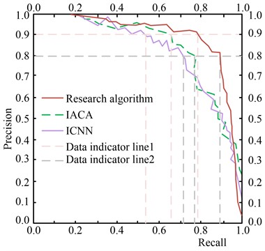
The PR curves in Fig. 7 show that when the precision rate of the algorithm is 0.8 and 0.9, the corresponding recall rates are 0.893 and 0.785, respectively. The above results indicate that the precision and recall values of ICNN and IACA are smaller for the same experimental conditions. This suggests that the proposed algorithm offers a more thorough service for the robotic arm vibration suppression system and has a higher accuracy rate in the optimisation selection of the system. The higher recall rate also improves the overall usage of the Six-DOFrobotic arm in the market. With this in mind, the study compares the mean absolute percentage error (MAPE) under different data sets tested, as shown in Fig. 8.
Fig. 8Mean absolute percent error contrasts across different data sets
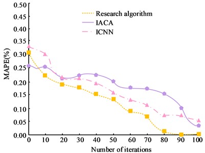
a) Cornell dataset
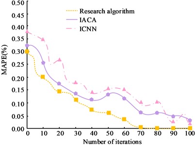
b) Jacquard data set
Fig. 8(a) is the test of MAPE on the Cornell dataset; Fig. 8(b) is the test of MAPE on the Jacquard dataset. From Fig. 8, it can be observed that as the number of iterations increases, the total MAPE values of all three algorithms on different data sets show a significant decreasing trend. Among them, the research algorithm has a lower MAPE value compared to the other three algorithms. In Fig. 8(a), the research algorithm has the smallest MAPE value when the number of iterations reaches 80, which is close to 0. The MAPE values of IACA and ICNN are 0.452 and 0.501 respectively, which are significantly larger than the research algorithm. In Fig. 8(b), when the MAPE value of the research algorithm is 0, the corresponding number of iterations is 70. The significant difference between the MAPE values of the research algorithm and the other algorithms can be seen on the basis of the significance results. This indicates that the algorithm proposed in the study has less error and better performance in the measurement of robotic arm tremor suppression.
4.2. Analysis of the practical application effect of the six degrees of freedom manipulator bearing chatter suppression strategy
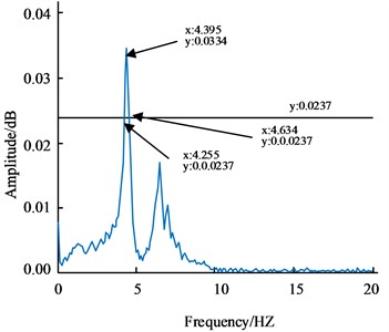
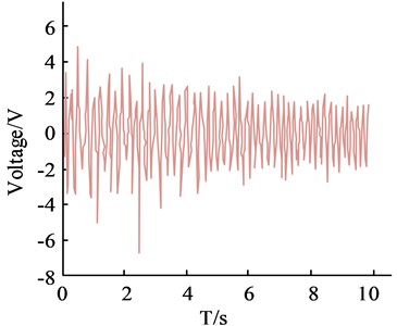
The Six-DOF robotic arm tremor control system designed in the study is a control system under a PID controller. As the control implementation is piezoelectric sheet control, the output of the controller is the voltage acting on the piezoelectric sheet and the flexible arm model can be chosen as the spatial equation of state. The research design model shows that the intrinsic frequency, which can be determined using the frequency response method, and the structural damping ratio can both be used to solve the equation of state for the flexible mechanical arm rod. A swept output signal of 0.1 to 10 Hz is set in the signal generator for 10 s, and a sampling frequency of 90 Hz is selected for the vision measurement system. The data measurement is swept ahead of time to excite for a specific amount of time, while the acquired signal is analysed by digital signal processing. The results of the swept frequency excitation response and response spectrum are presented in Fig. 9 to verify that data is not lost.
Fig. 9Sweep excitation response and response spectrum results
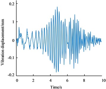
a) The frequency sweep excitation response
b) The response spectrum result
Fig. 9(a) is the frequency sweep excitation response; Fig. 9(b) is the response spectrum result. The data measurement is swept ahead of time to excite for a specific amount of time, while the acquired signal is analysed by digital signal processing. The results of the swept frequency excitation response and response spectrum are presented in Fig. 9 to verify that data is not lost. In Fig. 9(b), it can be seen that the peak frequency is 4.395 HZ, so the inherent frequency is 27.615 HZ. On the spectrum curve, make a straight line parallel to the -axis with a height of of the peak, i.e. 0.0237. The intersection of the straight line and the spectrum curve is the half-power point, i.e. (4.255, 0.0237) and (4.634, 0.0237), corresponding to frequencies of 4.255 HZ and 4.634 HZ. The damping ratio is estimated to be 0.0431 according to the half power bandwidth method. in of the equation of state is the force factor, which affects the output ratio. To obtain its value and verify the accuracy of the equation of state, the simulated equation of state response and the actual experimental response under the same excitation are compared and calculated to determine the output ratio. Using the above excitation experimental setup, the signal generator outputs a sinusoidal signal with a frequency of 4.395 Hz, which is amplified by the signal amplifier to a peak value of 40 V. The results are compared with a sinusoidal signal with a frequency of 4.395 Hz and a peak value of 40 in Simulink as input to obtain the equation of state response and adjust the spatial equation of state parameters. When is 0.27, the equation response is the same as the measured result. The final corresponding spatial equation of state is obtained as . In addition to this, the study selected the Z-N method for determining the parameters of the PID control technique and applied it together with the research algorithm to the Six-DOFrobotic arm control system, the results of which are shown in Fig. 10 for comparison.
Fig. 10Comparison of the control results under the different algorithms
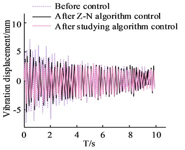
a) Comparison results of vibration displacement before and after control
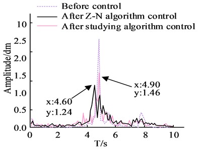
b) Spectrum comparison results before and after control
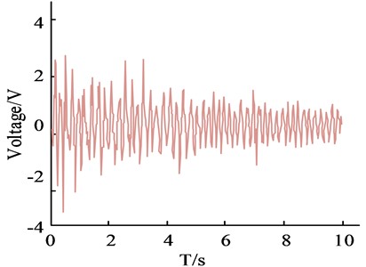
c) PID control output under Z-N method parameters
d) Study PID control output under algorithm parameters
Fig. 10(a) is the comparison results of vibration displacement before and after control; Fig. 10(b) is Spectrum comparison results before and after control; Fig. 10(c) is the PID control output under Z-N method parameters; Fig. 10(d) is the Study PID control output under algorithm parameters. Examination of the results in Fig. 10 demonstrates that the settings produced by both algorithms may govern the suppression of tremor in the robot arm. The two algorithms offer a superior tremor suppression effect on the tremor during the robotic arm's commencing operation phase and have a more substantial control effect in the first few seconds, according to the control time domain. The average control effects of the Z-N technique and the fish swarm method were calculated using the results of the spectrum analysis as the average control effect, and were found to be 51.56 % and 42.96 %, respectively. It is evident that the controller operating under the artificial fish swarm optimised parameter methodology has a greater control output signal when compared to the controller operating under the parameters of the Z-N technique. The study's proposed algorithm has better control performance, which effectively verifies the algorithm's superiority and better chatter suppression impact, according to the spectrum results. The specific effect is depicted in Fig. 11 and is the result of testing and recording the six-DOF robotic arm end-genuine effector's tremor suppression effect.
Fig. 11Tremor inhibition effect at the end of the manipulator actuator
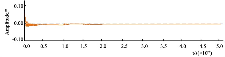
a) First experiment
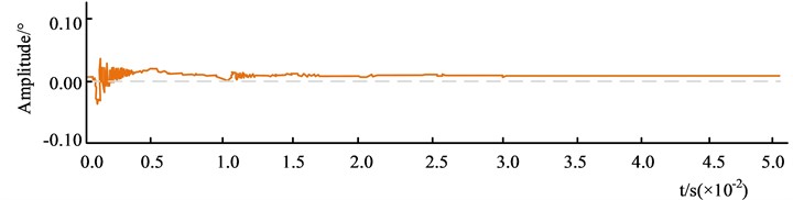
b) Second experiment
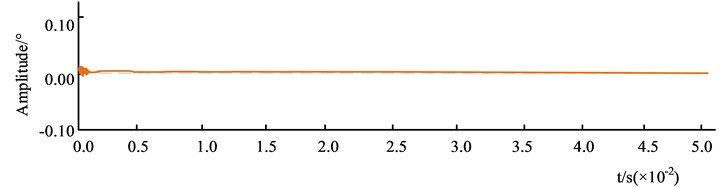
c) The third experiment
Fig. 11 shows the effect of tremor suppression on the robotic arm. The overall experiment was conducted three times, with the system running for 0.05 s. The "+" and "-" indicate the occurrence of rightward and leftward tremor movements of the robotic arm, respectively. Fig. 11(a) shows the first experiment. At the beginning of the experiment, the tremor amplitude of the arm decreased from 0.05° to 0.0001 s, and then trembled to the left, after which the tremor amplitude was more stable but always less than 0.00°. Fig. 11(b) shows the second experiment. At the beginning of the experiment, the amplitude of the arm tremor started to tremble rapidly from the right to the left and stabilized after 0.01 s, but the amplitude was always greater than 0.00°. Fig. 11(c) shows the third experiment. The robot arm tremor amplitude changes rapidly at the start of the experiment, tends to 0 at 0.0001 s, and remains stable thereafter. The data shows that the research algorithm has a high adaptability to robotic arm tremor suppression, and the amplitude gradually decreases with the number of experiments. The algorithm is able to converge to 0 quickly and can be applied to robotic arm tremor suppression.
5. Conclusions
The effective suppression of bearing tremors in robotic arms is an important guarantee of their service life and safety performance. The study takes a Six-DOF modular robotic arm and uses the parameters of the standard D-H coordinate system to establish the corresponding coordinate system, from which the forward and inverse kinematic equations are obtained. Subsequently, based on the measurement of its end vibration displacements, the real-time tremor displacement signals measured visually were used as control inputs and combined with an AFSA for parameter optimisation. The results showed that the artificial fish swarm-PID control technique had a maximum fitness value of 94 at 60 iterations in the Cornell dataset. In the Jacquard dataset, the method reached a fitness of 99 at the 9th iteration. in a comparison of PR curves for the Cornell dataset instances, the method had a recall of 0.893 at a precision of 0.8. In the Jacquard dataset, the mean absolute percentage error results for the method corresponded to 70 iterations at a MAPE value of 0, when the MAPE values for IACA and ICNN were 0.387 and 0.241 respectively. In tremor suppression at the end of the robotic arm actuator, the first experiment of the method trembled to the left at 0.0001 s, after which the tremor amplitude was more. The amplitude of the tremor was then more stable, but remained less than 0.00°. In the second experiment, the amplitude of the arm tremor quickly started to tremble from the right to the left and stabilized after 0.01 s, but the amplitude was always greater than 0.00°. In the third experiment, it converged to 0 at 0.0001 s and remained stable thereafter. This indicates that the proposed method is highly adaptable and can achieve effective suppression of bearing vibrations. The study, however, employs machine vision to assess vibration without taking into account low frequency vibration’s actual situation and is unable to measure high frequency vibration, which needs to be optimised by expanding the measurement range.
References
-
L. Ma, J. Wang, and C. Li, “Vibration suppression of a rotor system with a nonlinear MR damper,” Archive of Applied Mechanics, Vol. 91, No. 9, pp. 4053–4068, Sep. 2021, https://doi.org/10.1007/s00419-021-01993-3
-
M.-X. Guo, J. Liu, L.-M. Pan, C.-J. Wu, X.-H. Jiang, and W.-C. Guo, “An integrated machine-process-controller model to predict milling surface topography considering vibration suppression,” Advances in Manufacturing, Vol. 10, No. 3, pp. 443–458, Sep. 2022, https://doi.org/10.1007/s40436-021-00386-7
-
F.-C. Wang, C.-H. Lee, and R.-Q. Zheng, “Benefits of the inerter in vibration suppression of a milling machine,” Journal of the Franklin Institute, Vol. 356, No. 14, pp. 7689–7703, Sep. 2019, https://doi.org/10.1016/j.jfranklin.2019.02.002
-
G. Borque Gallego, L. Rossini, T. Achtnich, D. M. Araujo, and Y. Perriard, “Novel generalized notch filter for harmonic vibration suppression in magnetic bearing systems,” IEEE Transactions on Industry Applications, Vol. 57, No. 6, pp. 6977–6987, Nov. 2021, https://doi.org/10.1109/tia.2021.3062587
-
Y. Yoshiura, Y. Asai, and Y. Kaku, “Anti-resonance vibration suppression control in full-closed control system,” IEEJ Journal of Industry Applications, Vol. 9, No. 3, pp. 311–317, May 2020, https://doi.org/10.1541/ieejjia.9.311
-
Q.-D. Hoang, J. Park, and S.-G. Lee, “Combined feedback linearization and sliding mode control for vibration suppression of a robotic excavator on an elastic foundation,” Journal of Vibration and Control, Vol. 27, No. 3-4, pp. 251–263, Feb. 2021, https://doi.org/10.1177/1077546320926898
-
C. Peng, M. Zhu, Y. Wang, and J. Jiang, “Phase-based video measurement for active vibration suppression performance of the magnetically suspended rotor system,” IEEE Transactions on Industrial Electronics, Vol. 68, No. 2, pp. 1497–1505, Feb. 2021, https://doi.org/10.1109/tie.2020.2967725
-
N. Sang et al., “A dual-sided hybrid excitation eddy current damper for vibration suppression in low damping linear motor system,” IEEE Transactions on Industrial Electronics, Vol. 68, No. 10, pp. 9897–9907, Oct. 2021, https://doi.org/10.1109/tie.2020.3026266
-
J. Li, G. Liu, P. Cui, S. Zheng, and Q. Chen, “Synchronous vibration suppression of magnetically suspended rotor system using improved adaptive frequency estimation,” IEEE Sensors Journal, Vol. 20, No. 19, pp. 11212–11220, Oct. 2020, https://doi.org/10.1109/jsen.2020.2997046
-
C. J. Lin, W. L. Chu, C. C. Wang, C. K. Chen, and I. T. Chen, “Diagnosis of ball-bearing faults using support vector machine based on the artificial fish-swarm algorithm,” Journal of Low Frequency Noise, Vibration and Active Control, Vol. 39, No. 4, pp. 954–967, Jul. 2020, https://doi.org/10.1177/146134841986182
-
Y. Xing, X. Wang, and Q. Shen, “Test case prioritization based on artificial fish school algorithm,” Computer Communications, Vol. 180, No. 12, pp. 295–302, Dec. 2021, https://doi.org/10.1016/j.comcom.2021.09.014
-
W. Ren, X. Wen, and S. Lai, “Digital real-time rotating speed measuring and fuzzy PID control algorithm design for the multi-speed electronic let-off system,” Fibres and Textiles in Eastern Europe, Vol. 29, No. 4(148), pp. 48–55, Aug. 2021, https://doi.org/10.5604/01.3001.0014.8231
-
M. G. Krishnan and A. Sankar, “Image space trajectory tracking of 6-DOF robot manipulator in assisting visual servoing,” Automatika, Vol. 63, No. 2, pp. 199–215, Apr. 2022, https://doi.org/10.1080/00051144.2021.2022889
-
V. Lakshmi, S. K. Mangipudi, and R. R. Manyala, “Control constraint-based optimal PID-PSS design for a widespread operating power system using SAR algorithm,” International Transactions on Electrical Energy Systems, Vol. 31, No. 12, pp. 13146–13147, Dec. 2021, https://doi.org/10.1002/2050-7038.13146
-
X. Lv, Z. Tan, K. Chen, and Z. Yang, “Improved recurrent neural networks for online solution of Moore‐Penrose inverse applied to redundant manipulator kinematic control,” Asian Journal of Control, Vol. 22, No. 3, pp. 1188–1196, May 2020, https://doi.org/10.1002/asjc.1988
-
T. Liu, W. Xu, T. Yang, and Y. Li, “A hybrid active and passive cable-driven segmented redundant manipulator: design, kinematics, and planning,” IEEE/ASME Transactions on Mechatronics, Vol. 26, No. 2, pp. 930–942, Apr. 2021, https://doi.org/10.1109/tmech.2020.3013658
-
Y. Chen, W. Li, and Y. Gong, “Static modeling and analysis of soft manipulator considering environment contact based on segmented constant curvature method,” Industrial Robot: the international journal of robotics research and application, Vol. 48, No. 2, pp. 233–246, Jul. 2021, https://doi.org/10.1108/ir-07-2020-0131
-
J. Zhao, B. Xiu, J. Wang, and X. Zhang, “Adaptive task‐space cooperative tracking control for manipulators with a desired trajectory estimator and a velocity observer,” International Journal of Robust and Nonlinear Control, Vol. 32, No. 7, pp. 4214–4235, May 2022, https://doi.org/10.1002/rnc.6017
-
L. Guanming, Q. Haibo, and G. Sheng, “Sensitivity analysis of a planar parallel manipulator with kinematic redundancy,” Journal of Mechanical Engineering, Vol. 56, No. 23, p. 45, 2020, https://doi.org/10.3901/jme.2020.23.045
-
T. Zheng, F. Zheng, X. Rui, L. Yan, K. Niu, and F. Zhang, “Analysis of a three-extensible-rod tracker based on 3-RPS parallel manipulator for space large deployable paraboloid structure with power and communication integration,” Acta Astronautica, Vol. 169, No. 4, pp. 1–22, Apr. 2020, https://doi.org/10.1016/j.actaastro.2019.12.021
-
Selvi, “Kinematic analysis of overconstrained manipulators with partial subspaces using decomposition method,” Robotica, Vol. 40, No. 6, pp. 1783–1798, Jun. 2022, https://doi.org/10.1017/s0263574721001351
About this article

The authors have not disclosed any funding.
The datasets generated during and/or analyzed during the current study are available from the corresponding author on reasonable request.
Man Zheng designed and proceeded the experiment, and wrote the draft. Jun Jin is responsible for the processing data and translation, and revised the draft. All authors have reviewed the article.
The authors declare that they have no conflict of interest.
