Abstract
An automobile active accelerator pedal (AAP) warns the driver about an emergency. A tubular electromagnetic linear actuator is the key component to create an impact or vibration, but it has a large cogging force due to a steel core that causes instabilities. Accordingly, we propose an AAP with a coreless tubular electromagnetic linear actuator, and verify its performance using dynamic experiments.
1. Introduction
A car accident is caused by factors such as the driver’s negligence, inadequate vehicle distance, and sleepiness [1-3]. To reduce accidents, various warning systems based on visual, auditory, and tactile senses have been researched [4, 5]. Among the five human senses, the tactile sense produces the fastest response. An automobile active accelerator pedal, which transfers vibration to the driver’s foot in an emergency, is an advanced system that make the drive aware of an emergency in a quick and reliable way. [6] The organization of the AAP system is based on the concept of active safety in order to reduce vehicle speed before a car accident. Fig. 1 shows a diagram of an active accelerator pedal system. The AAP system is comprised of a sensor, accelerator control unit, actuator, pedal module, and the driver.
Fig. 1Diagram of active accelerator pedal system

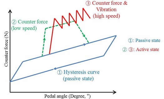
The AAP system operates in different modes depending on the driving speed. At a low driving speed, the AAP system provides a counter-force at a specific depth to prevent the driver from depressing the accelerate pedal any farther. At high driving speed, it provides vibration in addition to counter-force to give an emergency warning to the driver. The AAP system should produce the same amount of force as the driver or more. Drivers normally press the accelerator pedal with approximately 30 to 40 N of force. Otherwise, the driver cannot feel any warning [8]. As shown in Fig. 2, the only spring and friction in the pedal system be produced hysteresis in order to return the original position of the accelerator pedal as shown by ①. The counter-force and vibration location can be created anywhere on the graph within the range of a full rotation of the accelerator pedal.
② represents the active state at low speed driving, which is a generated continuous counter-force so that the driver does not continue to press the pedal. Thus, the driver cannot press the accelerator pedal further in a passive manner. Also, the AAP system produces hysteresis during high speed driving as shown by ③. Therefore, the tubular electromagnetic actuator creates a counter-force, and vibration is the key component of an AAP [7]. However, this actuator with core has large cogging force that causes instabilities in the AAP and produces an uncomfortable feeling in the user’s foot. Thus, we considered an AAP with a coreless tubular linear actuator. A prototype was manufactured, experiments were performed, and the counter-force and vibration were measured.
Fig. 2Active and passive counter-force curve
2. Active accelerator pedal system with a coreless tubular electromagnetic linear actuator
Fig. 3 shows a schematic diagram of the proposed AAP system. It consists of an accelerator pedal, mechanical spring, AAP frame, and coreless tubular electromagnetic linear actuator.
Fig. 3Design of AAP system with tubular linear actuator
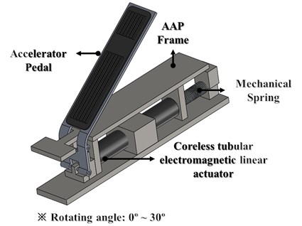
It has a simple structure and a 30° full stroke. Also, the AAP system has been applied as a mechanical coil spring to create hysteresis. This AAP system with a coreless linear actuator has a significant safety advantage because it can be used at both low and high speed. Also, it has the advantage of stability and accuracy. The actuator has twelve electromagnetic coils which are marked with the two-phase A and B as shown in Fig. 4.
Table 1Specification of the coreless tubular linear actuator
Components | Unit | Figures |
Magnet axial length | mm | 22 |
Magnet radial length | mm | 9.7 |
Airgap | mm | 1.1 |
Coil part thickness | mm | 5.2 |
Fig. 4Section view of the tubular linear actuator
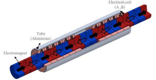
When electric current flows in the electromagnetic coil of a two-phase A and B, the moving part vibrates due to the Lorentz force. This Lorentz force is described as follows [12]:
where – number of electric coil turns, – magnetic force, – input electric current, – effective coil length.
3. Experiments
3.1. Prototype of experiments
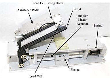
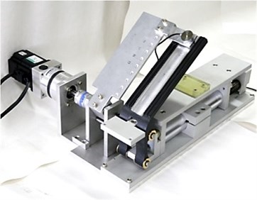
The AAP system must generate about 1.7 to 3.5 kgf of basic counter-force (passive force) and 0.7 to 1.5 kgf of counter-force (hysteresis range). The rotation angle of the accelerator pedal is slightly different for each car company, so about 30° of the maximum rotation was used arbitrarily in this research. Ed. highlight-is this what you mean? When a driver presses on the accelerator pedal, the moving part is moved in a horizontal direction in the passive state. Thus, a compressive force is transmitted to the accelerator pedal by a spring [13]. Also, when a danger signal is captured through various sensors in the vehicle, a control unit passes the signal to the tubular electromagnetic linear actuator in order to generate a counter-force. Fig. 5 shows the experimental equipment and prototype of the proposed AAP system with coreless actuator for dynamic verification. The equipment consists of a load cell, an accelerator pedal, an accelerator assistant pedal (for testing), a coreless tubular electromagnetic linear actuator, and a mechanical spring.
The specifications of the load cell and the mechanical part are shown in Table 2.
Fig. 5Accelerator performance test setup equipment with developed AAP system
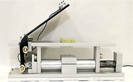
Fig. 6(a) shows the name of each part in the AAP system. The assistance pedal was designed to measure the direct counter-force from the accelerator pedal. The load cell is attached to the assistance pedal, as shown in Fig. 6(b). Also, we made holes in the assistance pedal for the measurement of the counter-force variation in accordance with the load cell position.
Fig. 7 shows the overall system configuration for the experiment [14].
Table 2Specifications of mechanism and load cell
Mechanism | Load cell specifications | ||
Weight (kg) | 7.5 | Model | CMM2-K10 |
Length (mm) | 450 | Weight (kg) | 0.3 |
Height (mm) | 105 | Rated output (mV/V) | 0.7 to 1.2 |
Depth (mm) | 80 | Input resistance (Ω) | 350 |
Pedal rotation angle (°) | 30 | Output resistance (Ω) | 350 |
Stroke (mm) | 30 | Rated load (kgf) | 10 |
Fig. 6AAP test system and load cell
a) Parts of the AAP test system
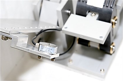
b) Force sensor (100 N capacity)
Fig. 7Data acquisition process flow
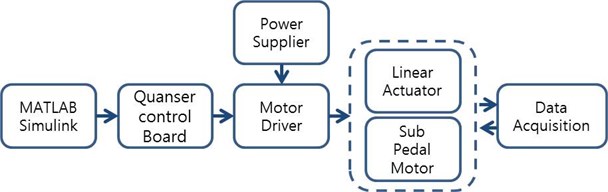
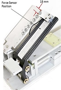
Fig. 8Force sensor positions on the pedal: ① = P1, ② = P2, ③ = P3, ④ = P4, ⑤ = P5, ⑥ = P6, and ⑦ = P7
3.2. Passive state experiment
Fig. 8 shows the position of the load cell for the AAP system experiment. Experiments were conducted at seven positions.
Fig. 9 shows that the counter-force, which is generated during the moving part of free motion by rotation of an accelerator pedal, is transmitted to the pedal in the passive state. The figure shows a progressive increase in the counter-force along the position of the load cell from ① (=P1) to ⑦ (=P7). Thus, we note that as the load cell is moved to the center of rotation, the torque increases.
Also, Fig. 9 shows the counterforce measurement according to the position of load cell at a) time area and b) pedal rotation angle area in the passive state. Here we can see the approximate hysteresis and the change of hysteresis from about 25 to 10 N.
Fig. 9Counterforce measurement according to the position of the load cell in a passive state: a) time area, and b) pedal rotation angle area
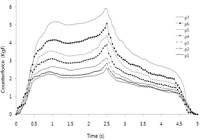
a)
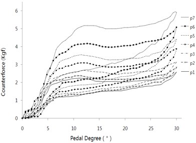
b)
3.3. Active state experiment
The active state experiment is the compulsory counter-force measurement in an emergency situation and during careless driving. This counter-force is a key component in reducing the vehicle speed in emergency situations.
Fig. 10 shows the AAP system with a coreless actuator, which has an assistance pedal and a connected motor with a link, for the experiment involving the active state by driving the motor at a constant speed.
Fig. 10Active actuator test experimental system
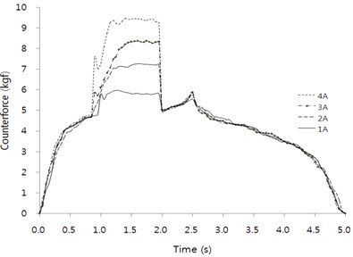
The load cell is attached to ① (=P1), and electric curren was applied to the actuator from 1 to 5 A in five intervals. The operating condition was a full stroke set to 5 s of recurrence time with respect to the initial position. Also, electric curren was applied in order to operate the tubular electromagnetic linear actuator between 1 and 2 s of operating time.
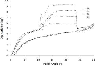
Fig. 11Actuator performance test according to electric current on position P1 on active condition: a) time area, and b) pedal rotation angle area
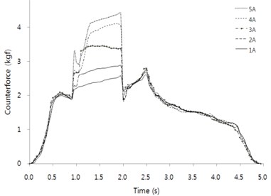
a)
b)
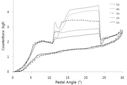
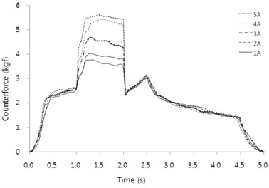
Fig. 11(a) and (b) show the counter-force on position ① (=P1) in the active condition time area and the pedal rotation angle area as hysteresis characteristics. Figs. 12-16 show the experimental results of the odd number positions (P1, P3, P5, and P7) instead of all positions.
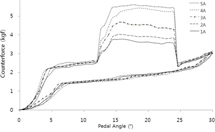
Fig. 12(a) and (b) show the results of the measured counter-force of time and rotation angle of the pedal at position 3.
Fig. 12Actuator performance test according to electric current on position P3 on active condition: a) time area, and b) pedal rotation angle area
a)
b)
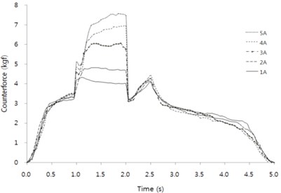
Fig. 13(a) and (b) show the results of the measured counter-force of time and rotation angle of the pedal at position 5.
Fig. 14(a) and (b) shows the results of the measured counter-force of time and rotation angle of the pedal on position 7.
When the vehicle is driving at high speed, transferred vibration to driver is a more efficient method than interruption of the acceleration pedal's movement. The following experiments show the results of the counter-force and vibration according to the time and angle of acceleration in an emergency situation at high speed. Figs. 17 and 18 show the results of an experiment at input frequencies of 15 and 17 Hz at position 1 of the load cell. The active state experiment during high speed driving was limited to load cell position P1, because the counter-force most accurately transmits to the driver during high speed driving. Also, in the previous experiment of the active state during low speed driving, we confirmed that the counter-force curves are proportional.
Fig. 13Actuator performance test according to electric current at position P5 for active condition: a) time area, and b) pedal rotation angle area
a)
b)
Fig. 14Actuator performance test according to electric current at position P7 for active condition: a) time area, and b) pedal rotation angle area
a)
b)
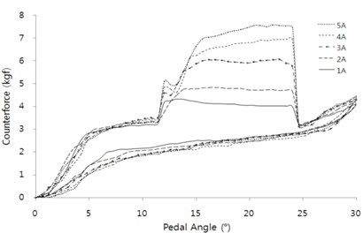
Fig. 15Actuator performance test with 15 Hz vibration according to electric current at position P1 in the active condition: a) time area and b) pedal rotation angle area
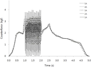
a)
b)
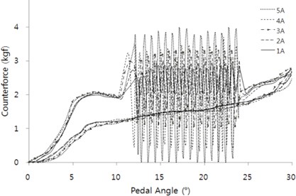
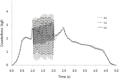
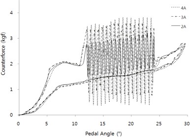
Fig. 15 shows counter-force and vibration in accordance with the electric current at 15 Hz of mechanical input frequency. The counter-force and vibration is small at 1 A, and a large amplitude of counter-force and vibration was generated at 5 A. So, the 1 and 5 A electric currents were excluded from the experiment because the difference in the force is large. Thus, 2, 3, and 4 A electric currents were applied to the AAP system at a 17 Hz mechanical input frequency, as shown Fig. 16. When compared at 15 Hz and 17 Hz, the counter-force and vibration amplitude at a high frequency tended to decrease.
Fig. 16Actuator performance test with 17 Hz vibration according to electric current at position P1 on active condition: a) time area, and b) pedal rotation angle area
a)
b)
4. Conclusions
We performed an experiment with an AAP system with a coreless tubular electromagnetic linear actuator for the improvement of efficiency and sense of difference. In the experiments, this AAP system exactly transferred the counter-force and vibration to the driver at the P1 pedal position. And we found a variety of the counter-force amplitude by applying from 1 to 5 A of electric current. We confirmed that the proposed AAP system is suitable for 3 A of electric current, because the amplitude difference of the counter-force is large at over 4 A of electric current.
In addition, a driver can respond faster to the warning because the amplitude of the counter-force and vibration was shown to be larger. Hence, this AAP system with a coreless linear actuator has sufficient applicability. Further study to examine the weight, size, and price of the device should be undertaken.
References
-
Scott J. J., Robert Gray A comparison of tactile, visual, and auditory warnings for rear-end collision prevention in simulated driving. The Journal of the Human Factors and Ergonomics Society, Vol. 50, Issue 2, 2008, p. 267-275.
-
Continental Co. http://www.conti-online.com.
-
Road Traffic Authority. http://www.rota.or.kr.
-
Hibino Katsuhiko, Takao Nishimura, Noriaki Shirai Obstacle warning system for a vehicle. U.S. Patent No. 5,751,211, 1998.
-
Suzuki Keisuke, Hakan Jansson An analysis of driver’s steering behaviour during auditory or haptic warnings for the designing of lane departure warning system. JSAE review 24.1, 2003, p. 65-70.
-
Hjälmdahl Magnus, András Várhelyi Speed regulation by in-car active accelerator pedal: Effects on driver behavior. Transportation Research Part F: Traffic Psychology and Behaviour 7.2, 2004, p. 77-94.
-
Lee J. Y., Kim J. H., Lee J. W. Design and analysis of electromagnetic tubular linear actuator for higher performance of active accelerate pedal. Journal of Magnetics, Vol. 14, Issue 4, 2009, p. 175-180.
-
Jae-Yong Lee, Jin-Ho Kim, Sang-Min Woo, Jeh-Won Lee A novel design of active accelerator pedal using linear electromagnetic actuator. Journal of Mechanical Science and Technology, Vol. 24 Issue 1, 2010, p. 207-210.
-
Zhu Z. Q., et al. Reduction of cogging force in slotless linear permanent magnet motors. IEE Proceedings on Electric Power Applications, Vol. 144, Issue 4, 1997.
-
Ishiyama M., Makoto I., Kitaoka T., Matsumoto Y., Yagoto M. Linear Motor. Patent #5,955,798, 1999.
-
SeMyung Park The Research on the Generation System Embedded in Cellular Phone for Nonutility Generation. Yeungnam University, M.S. Theses, 2012.
-
Zhu Z. Q., Hor P. J., Howe D., Rees-JonesJ. Novel linear tubular brushless permanent magnet motor. 8th International Conference on Electrical Machines and Drives, Vol. 444, 1997, p. 91-95.
-
Hongfeng Li, Changlian Xia Halbach array magnet and its application to pm spherical motor. ICEMS International Conference on Electrical Machines and Systems, 2008, p. 3064-3069.
-
MurphyB. C. Design and Construction of a Precision Tubular Linear Motor and Controller. M.S. Thesis, Deptment of Mechanical Engineering, Texas A&M University, 2003.
About this article

This research was supported by Yeungnam University research grant in 2015.
