Abstract
The nonlinear dynamic characteristics of plane cracked beam subjected to a harmonic load at the tip are researched. A crack opens and closes during vibration that is simulated as a frictionless plane contact problem, and a finite element contact model for a cantilever cracked beam is established. The quarter-point element is used to describe the crack tip singularity. Based on the proposed finite element contact model, the influence of excitation frequency, crack depth and crack position on nonlinear dynamic characteristics are discussed in detail. Relative amplitude of frequency spectrum with respect to different factors is analyzed to realize sub-harmonics or super-harmonics of cracked beam. The research results demonstrate that there is obvious nonlinear dynamic behavior for plane beam with a fatigue crack, and the different feature of frequency spectrum can be used to identify the beam damage in structure. Meanwhile, the strategy of experimental validation to the FEM results is discussed.
1. Introduction
The emergence and propagation of the crack in structural components arise from long-term fatigue, which influence on the safety and reliability of structure at some extent. Therefore, vibration analysis and crack identification for a cracked structure have been received extensive attention, including theoretical study, numerical simulation and experimental test [1-2]. There are two types of crack model, full open crack model and breathing crack model, are assumed that apply for vibration analysis and crack identification. For simplicity, most scholars usually used a full open crack model to study the dynamic response of cracked structure ignoring nonlinear effects of fatigue crack. However, a fatigue crack is not generally opening state. Actually, it is a cyclical opened-closed state with a strong nonlinear process. Gudmundson [3] compared the natural frequencies of cracked structure by experimental test to calculation by the full open crack model, the results indicated that the open crack model will lead to lower assess the extent of damage to the structure.
The breathing crack model is in accord with an actual fatigue crack by considering nonlinear dynamic characteristics during the crack opens-closes process [4-10]. Shen and Chu [4] conducted comparative researches for depicting dynamic response due to crack by virtue of a breathing crack model and a bilinear spring-mass oscillator. Sundermeye and Weave [5] also used a bilinear spring-mass oscillator system to study the weak nonlinear vibration characteristics of cracked beam, and identified the crack location, crack depth and crack opening load based on corresponding vibration characteristics. Ruotolo etc. [6] used the finite element analysis to study the dynamic behavior of cantilever crack under harmonic loads, where fatigue crack was simulated by transient breathing crack model, and higher order frequency response function was applied for the analyzing nonlinear characteristics. Pugno etc. [7] presented a nonlinear systems of algebraic equations to study on the dynamic response based on crack breathing phenomenon, analyzed nonlinear dynamic response behavior of a multiple breathing cracked beam under harmonic loads. Loutridis etc. [8] applied Hilbert-Huang Transform (HHT) to obtain the instantaneous frequency of cracked beam, and analyzed instantaneous frequency characteristics under harmonic excitation load. Giannini etc. [9] studied the dynamic characteristics of beam with multiple breathing cracks, and developed an approach for evaluation of natural frequencies and mode shapes. Vigneshwaran and Behera [10] developed an identification method by considering several modes with different modal curvature, and evaluated the relationship between the harmonic component amplitude and damage characteristics.
In this paper, an elaborate two-dimensional finite element contact model is established to study the nonlinear dynamic characteristics. Fatigue crack tip effect is simulated by singular element, and fatigue crack breathing property is simulated by frictionless contact element. Based on proposed finite element model, nonlinear dynamic characteristics of a cantilever breathing crack beam, under harmonic load excitation, has been conducted. According to sub-harmonic, ultra-harmonic vibration characteristics, the influence of the excitation frequency, crack location and crack depth on nonlinear dynamic behavior are discussed.
2. A finite element model of a breathing crack beam
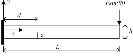
A cantilever beam with a fatigue crack is studied in this paper. The sketch of a cantilever beam is shown in Fig. 1, where length is , height is , width is , crack depth is . The free end of the cantilever beam is subjected to harmonic load . A finite element model of cracked beam, based on plane stress condition, is established according to the load characteristics. Here, the dimensionless parameters, and are defined to represent the relative crack depth, the relative crack location respectively.
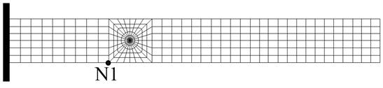
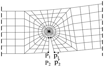
Fig. 1a) The sketch of a cantilever cracked beam, b) Overall finite element meshing, c) Local meshing of crack area
a)
b)
c)
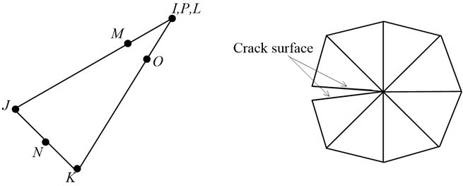
Due to the presence of the crack, there is singularity feature in the stress field at the crack tip. Therefore, the crack tip meshing is of great important to obtain the accurate calculation results in finite element analysis. In general, there are two ways to deal with the meshing of crack tip: (i) enforce the mesh density around the crack tip; (ii) use singularity elements to describe the crack tip. In this paper, alternatively, the singularity elements of 2-D plane are used to depict the singularity behavior of stress field at crack tip. A 8-node element adjacent to the quarter-point element along the crack face is utilized. The overall finite element mesh of a cracked beam is displayed in Fig. 1(b), and more detailed meshing of crack tip area is shown in Fig. 1(c). The detailed contents about quarter-point elements can refer to literature [11].
Fig. 2Sketch of singularity element for crack tip
3. Contact model for a cantilever beam with a fatigue crack
When two or more bodies come into contact, the contact region may increase or decrease due to different external load. Changing boundary conditions introduce a strong nonlinear contact problem which can be solved by finite element method. In this paper, the breathing crack is modeled as face-to-face frictionless contact problem. The crack interface can be regarded as contact pairs. In principle, the contactor surface is attached to elastic body and target surface on the rigid body. The crack surface on the left is as contactor surface and target surface on the right side. A difference between the contactor surface and the target surface is that the target surface can insert contactor body, but the contactor surface cannot insert the target body.
There are three contact conditions of crack interface:
1) The crack interface fully opens and no contact between the contactor surface and the target surface.
2) The crack interface fully closes and overall contact between the contactor surface and the target surface. If the initial crack interface closes, the displacements of the contactor pairs can be expressed as:
where, is node displacement, subscript expresses horizontal direction, superscript , are the left and the right crack interface respectively.
3) The crack interface opens-closes partly, the pressure of contact surface may be release or accumulation, which is so-called breathing crack.
Compared with other algorithms, the extended Lagrangian algorithm is unlikely to cause ill, calculated contact stiffness is more reasonable. Therefore, the extended Lagrangian algorithm is adopted in this paper to solve dynamic contact problem. The affects of crack surface frication on the nonlinear response can be ignored. The virtual work equation is obtained based on the virtual principle:
where is the total potential energy; , are the tangent and normal traction components respectively; , are the insignificant overlaps, which is greater than zero; , are the tangent and normal gap between the contactor nodes and the target nodes, can be expressed as follows:
The normal contact conditions can be expressed as the following equations by virtue of Bathe’s definition [12]:
When , no contact and crack fully opens. When , overall contact and crack closes. If when the crack opens, While the crack closes, , .
Newton- Raphson equation of the finite element contact model is expressed as:
where, is asymmetric initial stress matrix introduced by a curved surface for contact, is external node force vector, is stress matrix.
The finite element software ANSYS is utilized to establish numerical model. CONTA172 is selected as contact element and TARGE169 is selected as target element.
4. Nonlinear dynamic response analysis for a breathing cracked beam
Nonlinear dynamic characteristic of cantilever beam with a fatigue crack under harmonic load excitation mainly discussed [11] with respect to the fixed crack parameters ( 0.27, 0.5). However, the influence of crack parameters on the nonlinear behavior is not discussed. The thorough understanding of the dynamic characteristics is the basis for structural damage identification, especially for time-varying nonlinear system. Therefore, the study of nonlinear dynamic characteristics of cracked beam with different crack depth or different crack location should be focused. The physical parameters of cracked beam are listed in Table 1.
Table 1Physical parameters of cracked beam
Geometry properties | Values | Physical properties | Values |
Beam length (mm) | 300 | Elastic modulus (GPa) | 2.068 |
Beam width (mm) | 20 | Poisson’s ratio | 0.3 |
Beam height (mm) | 20 | Density of beam (Kg/m3) | 7850 |
In this paper, three main aspects of nonlinear dynamic characteristics of breathing cracked beam are studied:
1) The influence of excitation frequency on the nonlinear dynamic characteristics.
2) The influence of crack depth on the nonlinear dynamic characteristics.
3) The influence of crack location on the nonlinear dynamic characteristics.
For free vibration of the breathing cracked beam, the bilinear frequency is approximated as:
where, is so-called bilinear frequency of cracked beam, is the first natural frequency of the cracked beam with full opened crack, is the first natural frequency of the cracked beam with full closed crack, equivalent to the undamaged beam.
4.1. The validation of proposed finite element model for a breathing cracked beam
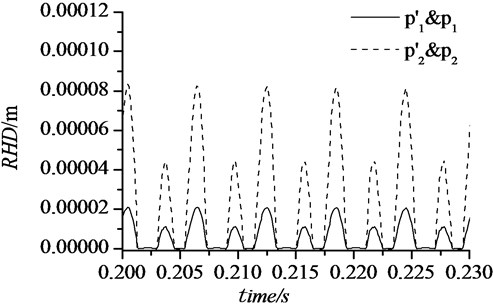
The feasibility of the proposed finite element model is validated by assessing the relative horizontal displacements of the contactor pairs & and &, shown in Fig. 1(c).
Fig. 3 shows the relative horizontal displacements (RHD) of the nodes & and & under the sinusoidal force. The location of the contactor pairs & and & are intervenient between the crack tip line and the beam surface. It is illustrated that RHD of the nodes & and & are varying circularly during the beam vibration. When the value of RHD equals to 0, or insignificantly less than 0, the crack is closed. Sometimes, crack interface may overlap each other in the numerical resolution. The crack interface gradually opens with the increase of RHD until the fully detachment. These phenomenon shows good agreement with the practical dynamic response of the cracked beam and demonstrates the proposed the finite element model is competent for non-linear analysis for a breathing crack beam.
Fig. 3Relative horizontal displacement of contactor pairs
4.2. The influence of external excitation frequency
The super-harmonic and sub-harmonic resonances of the breathing beam with four frequency excitations are investigated. The amplitude of excitation load 10 KN is adopted for the sinusoidal load. The ratio of excitation frequency to bilinear frequency of breathing crack () is represented by , and are respectively taken 1/4, 1/3, 1/2 and 2 in this paper. Where, crack location is 0.3, crack depth is 0.5, and calculation time step is taken as 1(60).
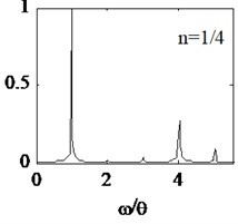
Based on the proposed beam parameters listed by Table 1, the 161.2 Hz and 183.5 Hz are calculated, and first frequency of breathing crack beam 171.6 Hz is obtained by the Eq. (7). The dynamic displacements of node N1 are extracted. Discrete Fast Fourier Transform (FFT) of the displacements is shown in Fig. 4. In Fig. 4, the ordinate is the normalized amplitude and the abscissa is the ratio of system frequency to excitation frequency.
When equals to 1/4, super-harmonic resonance occurs, corresponding frequency spectrum curve is shown in Fig. 4(a). It is illustrated that there are some harmonic components, relative to the 2, 3, 4, 5 times excitation frequency. Normalized amplitudes of every harmonic component are significantly different. Except for the harmonic component related to excitation frequency, the 4th harmonic component () appears maximum amplitude. Then, the frequency of 4th harmonic component is equivalent to frequency of the cracked beam. In addition, the normalized amplitudes of 3th or 5th harmonic component are significantly higher than 2th.
Fig. 4Amplitude spectrum under different excitation frequencies
a)
b)
d)
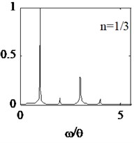
When equals to 1/3, super-harmonic spectrum curve is shown in Fig. 4(b). Similarly, the normalized amplitude of the 3th harmonic component is larger than the 2th or 4th. In addition, the normalized amplitude of the 5th harmonic component is smaller than 3th or 4th.
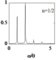
When equals to 1/2, the 1th frequency of cracked beam is sufficiently motivated and frequency spectrum curve is shown in Fig. 4(c). It is illustrated that the normalized amplitude of the 2th harmonic component significantly larger than the 1th, 3th, 4th and 5th. In addition, the normalized amplitude of 3th, 4th and 5th harmonic component gradually decrease.
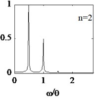
When equals to 2, the sub-harmonic resonance behavior occurs. The normalized amplitude of the 1/2 times of excitation frequency appears maximum value. The normalized amplitude of 1.5 and 2 times harmonic components gradually decrease, shown in Fig. 4(d).
It is illustrated that the facts are as follows: (1) When an external excitation frequency of the cracked beam is equivalent to integer times ( 2) or one-th ( 1/2, 1/3, 1/4), the harmonic components of the breathing cracked beam structure can be adequately motivated. Normalized amplitude of the first frequency of cracked beam becomes more significantly, relative to other harmonic components. (2) When the breathing cracked beam occur super harmonic or sub-harmonic resonance, normalized amplitude of the harmonic components adjacent to the 1th natural frequency is greater than those away from. (3) For super-harmonic ( 1/2) and sub-harmonic ( 2) resonance, the normalized amplitude of the 1th frequency is much greater than those excited by other system frequency.
4.3. The influence of crack depth
With the growth of service period, the crack will gradually propagate because of the fatigue cumulative. When the crack propagates to a certain extent, sudden collapse or destruction will happen in structure. Therefore, it is important to identify the crack depth. Understanding the nonlinear dynamic characteristics of cracked beam is the successful implementation for crack identification.
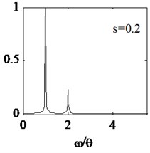
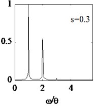
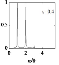
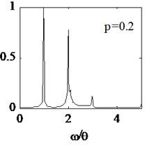
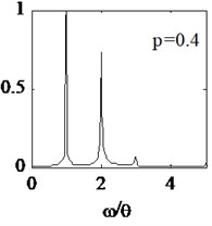
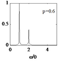
Here, crack location is 0.3 and crack depth is taken as 0.2, 0.3, 0.4 and 0.5 four cases. Cracked beam dynamic characteristic with four different crack depths are analyzed. In order to effectively study the nonlinear dynamic characteristics, external force frequency is defined 1/2 times , the calculation time step is still selected as 1(60). The steady-state displacements response of node N1 are extracted and respective spectral curves are shown in Fig. 5(a)-5(c) and Fig. 4(c).
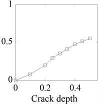
It is illustrated from the Fig. 5, for different crack depths, the normalized amplitude of 1th and 2th harmonic components are larger than other harmonics. With the increase of crack depth, the normalized amplitude of the first natural frequency increases. In order to describe the dynamic characteristics changes due to different crack depth, relative amplitude is defined as the ratio of amplitude of the 2th harmonic component to the total amplitude of all harmonic components. When the crack depth is 0.2, 0.3, 0.4, 0.5 respectively, the relative amplitude is 19 %, 35.5 %, 47.2 %, 55.5 %, as shown in Fig. 5(d). It is illustrated that the relative amplitude increases monotonically with the crack depth increases. Therefore, the relative amplitude of the system frequency can be used as a damage-sensitive feature to characterize the damage degree of cracked beam.
Fig. 5Amplitude spectrum with different crack depth
a)
b)
c)
d)
4.4. The influence of crack location
Conventional crack identification method, by virtue of modal parameters (natural frequency, mode shape, etc.) or derivative damage sensitive features, can identify the crack location in linear system. Nevertheless, for the nonlinear dynamic system, such as proposed breathing cracked beam, crack location changes will inevitably lead to differences from the response characteristics. Therefore, the analysis of nonlinear dynamic characteristics of breathing cracked beam with respect to different crack location is conducted in this paper, which has an effective meaning for identifying the crack location.
Where crack depth is 0.4, four different crack locations are selected and crack parameters are shown in Table 2. Excitation frequency is still defined 1/2 times , the calculation time step is still selected as 1(60). The displacements of node N1 are still extracted and respective spectral curves are shown in Fig. 6.
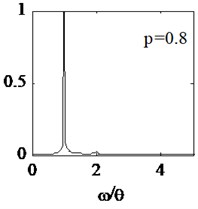
Fig. 6Amplitude spectrum with respect to different crack location
a)
b)
c)
d)
It is illustrated from the Fig. 6, harmonic components change with the crack location farther away from the fixed end of the cantilever beam. The positional parameter increases from 0.2 to 0.8, and the normalized amplitude of the 2th and 3th harmonic components gradually decreases. When 0.6, the normalized amplitude of 3th harmonic component almost disappear, and similar phenomena happen in terms of 2th harmonic component when 0.8. External force spectrum amplitude almost account for all the total amplitude, then nonlinearity dynamic characteristics of the breathing cracked beam is extremely weak. The and change rate of frequency () are listed in Table 3. It is illustrated that system stiffness is variable in terms of different crack location in spite of same crack depth. When the crack is close to fixed end of beam, the change of the structural stiffness is large, and nonlinear dynamic response is more obvious.
Table 2Crack location and depth parameters
Parameters | Values | |||
0.2 | 0.4 | 0.6 | 0.8 | |
0.4 | ||||
Table 3Frequency change of different crack locations
Parameters | Values | |||
0.2 | 0.4 | 0.6 | 0.8 | |
(Hz) | 164.3 | 175.4 | 181.3 | 183.2 |
5.5 % | 2.3 % | 0.59 % | 0.06 % | |
5. Strategy of experimental validation
It is well known that the experimental test is vital to validate the proposed theory and method. Meanwhile, it is very complicated to validate the nonlinear vibration problem of cracked beam by experiment, especially for making ideal breathing crack in beam. The authors are ready to carry out the physical model test to validate the FEM numerical results in the future. The strategy of experimental validation is summarized as follows:
1) Fatigue crack fabrication. It is extremely important to fabricate fatigue crack in the beam specimens. The physical and geometrical parameters of the beam specimen are arising from the data shown in Table 1. It is need at least eight ideal fatigue crack beam specimens to satisfy the experiment objective, the corresponding parameters are shown in Table 4. For each beam specimen, at first we will make tiny V-shaped groove in the beam based on the values in Table 4, and then, universal testing machine made in US MTS company is used to fabricate the fatigue crack by three-point bending test.
Table 4Crack parameters for each beam specimen
Specimen no. | Crack parameter values | |||
1-4 | 0.3, 0.2 | 0.3, 0.3 | 0.3, 0.4 | 0.3, 0.5 |
5-8 | 0.2, 0.4 | 0.4, 0.4 | 0.6, 0.4 | 0.8, 0.4 |
The purpose of fatigue test is to make fatigue crack, does not involve the study of the mechanism of fatigue fracture, therefore, the test loading condition can be relaxed. The constant amplitude sinusoidal cyclic loading will be used in the future experiment. Meanwhile, the maximum alternating stress intensity factor at the crack tip shall not exceed 0.6 to 0.7 times the critical stress intensity factor.
Based on fracture mechanics, the beam specimen fatigue crack propagate can divide into three phase, that is infancy phase, stable phase and rapid expansion phase. According to the S-N curve and the Paris equation, the fatigue test cycles can be preliminary estimated. In order to obtain the available beam specimens, we will stop test in a certain time interval to read crack development by microscope observation until obtaining the ideal fatigue crack beam specimen.
2) Harmonic vibration testing. After obtaining the ideal beam specimen with a fatigue crack, the harmonic vibration test will be conducted. The test system that including Bruel & Kjaer accelerometer, signal acquisition system, test control system and excitation setup, etc, will be established in the future. At first, the natural frequency of cantilever fatigue crack beam can be obtained to calculate the bilinear excitation frequency based on modal test. And then, for each beam specimens, the harmonic vibration response can be studied under the sinusoidal cyclic loading at the free end of the beam.
6. Conclusions
A two-dimensional finite element model of breathing cracked beam is established in this paper. Crack breathing behavior is simulated by frictionless contact element and four-node singular element. Based on the proposed finite element model, nonlinear dynamic characteristics of a breathing cantilever cracked beam are studied. The main conclusions are as follows:
The influence of the excitation load frequency on the nonlinear characteristics of the breathing cracked beam is significantly obvious. When 1/2, harmonic components of super harmonic resonance are most abundant, and non-linear dynamic characteristics are most obvious. In many harmonic components, the amplitude of harmonic components adjacent to system frequency is greater than those away from the system frequency.
Amplitude ratio of individual harmonic component is altered with respect to variable crack depth. With the increase of crack depth, the relative amplitude increases monotonically. The relative amplitude of the system frequency can be used as a damage-sensitive feature to characterize the damage degree of cracked beam.
For a breathing cantilever crack, change in the crack location causes a significant difference of variable structural stiffness. When the crack is close to fixed end of beam, the change of the structural stiffness is large, and nonlinear dynamic response is more obvious.
The results of experimental test will be presented by other paper in the future, which mainly discuss the experimental theme and results.
References
-
Dimarogonas A. D. Vibration of cracked structure: a state of the art review. Engineering Fracture Mechanics, Vol. 55, Issue 5, 1996, p. 831-857.
-
Hu J. S., Feng X., Li X., et al. State-of-the-art of the vibration analysis and crack identification of cracked beams. Journal of Vibration and Shock, Vol. 26, Issue 11, 2007, p. 146-152.
-
Gudmundson P. The dynamic behavior of slender structures with cross-sectional cracks. Journal of Mechanics Physics Solids, Vol. 31, Issue 4, 1983, p. 329-345.
-
Shen M. H. H., Chu Y. C. Vibrations of beams with a fatigue crack. Computers and Structures, Vol. 45, Issue 1, 1992, p. 79-93.
-
Sundermeyer J. N., Weaver R. L. On crack identification and characterization in a beam by non-linear vibration analysis. Journal of Sound and Vibration, Vol. 183, Issue 5, 1995, p. 857-871.
-
Ruotolo R., Surace C., Crespo P., et al. Harmonic analysis of the vibrations of a cantilevered beam with a closing crack. Computers and Structures, Vol. 66, Issue 6, 1996, p. 1057-1074.
-
Pugno N., Surace C., Ruotolo R. Evaluation of the non-linear dynamic response to harmonic excitation of a beam with several breathing cracks. Journal of Sound and Vibration, Vol. 235, Issue 5, 2000, p. 749-762.
-
Loutridis S., Douka E., Hadjileontiadis L. J. Forced vibration behavior and crack detection of cracked beams using instantaneous frequency. NDT&E International, Vol. 38, Issue 5, 2005, p. 411-419.
-
Giannini O., Casini P., Vestroni F. Nonlinear harmonic identification of breathing cracks in beams. Computers and Structures, Vol. 129, 2013, p. 166-177.
-
Vigneshwaran K., Behera R. K. Vibration analysis of a simply supported beam with multiple breathing cracks. Procedia Engineering, Vol. 86, 2014, p. 835-842.
-
Bathe K. J. Finite Element Procedure. Prentice-Hall, Upper Saddle River, NJ, 1996.
-
Andreaus U., Casini P., Vestroni F. Non-linear dynamics of a cracked cantilever beam under harmonic excitation. International Journal of Non-linear Mechanics, Vol. 42, Issue 3, 2007, p. 566-575.
About this article

