Abstract
Face gear drives are one of researching focuses of gear drives due to the insensitive characteristics of manufacture and alignment errors versus spiral bevel gear drives. However, dynamic behaviors and the best implementation of face gear drives with high contact ratios are not to be analyzed and constructed, and yet to be addressed by scholars. Thus, in this study, a face gear tooth modeling solution is constructed according to analysis of its tooth geometry, and implementations of three versions of face gear drives with high contact ratios is proposed as well as tooth geometries of standard version and three versions are simulated. In addition, a four DOF dynamic model of face gear drives is established, and dynamic behaviors of three versions of face gear drives with high contact ratios are extracted. Finally, strength of face gear drives based on ISO 6336 standard associated with the suggested equivalent face gear tooth is calculated to help determine which is the best implementation among three versions. These contributions would be helpful to improve engineering applications of face gear drives.
1. Introduction
Face gear drive is an intersection gear drive with cylindrical gears. Its insensitive characteristics of manufacture and alignment errors are significant versus spiral bevel gear drives. Thus, face gear drives always are one of focuses of non-traditional gear drives. There are a vast of issues discussing face gear drives in the past few years. A team as a core of Litvin investigated geometry, tooth contact analysis (TCA), stresses of face gear drives with a spur gear or a helical gear, and discussed applications of face gear drives in helicopter main gear boxes [1-6]. Barone, Borgianni and Forte evaluated the effect of misalignment and profile modification on face gear drives [7]. Guingand, De Vaujany and Jacquin experimented bending stresses of face gear drives under quasi-static torques [8]. Zanzi and Pedrero inspected modified geometry of face gear drives [9]. Frąckowiak constructed two manufcature solutions of face gear drives by CNC machines [10, 11]. Jin, Zhu and Bao established a non linear dynamic modeling of face gear drives with a spur gear [12]. Peng, DeSmidt, Saribay and Smith checked parametric instability of face gear drives [13]. Saribay, Bill, Smith and Rao studied elastohydrodynamic lubrications of Face Gear Pairs [14]. Hu, Tang, Chen and Lei assessed the effect of mesh stiffness on dynamic responses of face gear drives [15]. Wu probed elastohydrodynamic lubrication of orthogonal face gear drives [16]. However, dynamic behaviors, strength, and design suggestions of face gear drives with high contact ratios are not to be addressed by researchers according to limited published issues. Therefore, in this study, a face gear tooth modeling solution is constructed by analyzing tooth geometric characteristics, and three versions of face gear drives with high contact ratios, namely increasing addendum coefficient, decreasing pressure angle of reference circles, and combination with the first methods, are proposed and simulated in example cases. Moreover, a four DOF dynamic model is established, and dynamic behaviors of the example cases of face gear drives with high contact ratios are discussed. The analytic results indicate the effect of three versions on dynamic behaviors is obvious, but which is the best among three versions is difficult to determine only by dynamic analysis. Thus, a strength calculation solution of face gear drives, which is based on ISO 6336 standard associated with the proposed equivalent face gear teeth, is constructed, and strength of the example cases are calculated. Finally, a design suggestion of face gear drives with high contact ratios, which is based on comprehensive analysis of the dynamic behaviors and the strength in this issue, is obtained. These contributions would be benefit to improve engineering applications of face gear drives.
2. Constructed analysis solutions
2.1. Tooth modeling solution
A face gear tooth can be considered as a sequence in which modified involute gears are superimposed along its face width, and at the extreme outer radius, the tooth is pointing, namely positive modifications, as well as at the extreme inner radius, the tooth is undercut, mean to negative modifications. Therefore, a face gear tooth can be divided into two parts: one is a positive modification area, the other is a negative modification area. Thus, a non-modified position along face widths, that is a pitch, must be existed, and it can be expressed as:
Meanwhile, extreme inner and outer radiuses can be derived in a piecewise form as:
and modified coefficients of the extreme radiuses can be deduced in a piecewise form as:
where is a shaft angle, is a module, and are dedendum and base radiuses of generative gear respectively, is a pressure angle of reference circles, is an addendum pressure angle, is the number of generative gear teeth, is the number of face gear teeth, is an addendum coefficient, is a clearance coefficient and a drive ratio for generation can be written in:
2.2. Dynamic analysis solution
In this study, a three dimensional structure of face gear drives and its four DOF lumped parameter dynamic model, which are given in Fig. 1, are established for analyzing dynamic behaviors of standard version of face gear drives and three versions of face gear drives with high contact ratios.
Fig. 1A full structure of face gear drives and its four DOF lumped parameter dynamic model
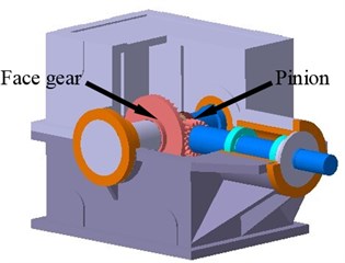
a) A three dimensional structure of face gear drives
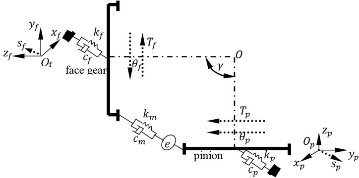
b) A four DOF dynamic model
As shown in Fig. 1, is a torsion degree of freedom, is a bending degree of freedom, is a torsion, is a bending stiffness, is a bending damping, subscript and express a face gear and a pinion respectively. In addition, is mesh stiffness, is mesh damping, and is a comprehensive meshing error.
Mathematic formulas of the four DOF dynamic model can be derived by:
where is a quality, is a moment of inertia, is a radius of base circles, is first derivative, is second derivative, and mesh force can be deduced as:
2.3. Strength analysis solution
Strength analysis solution of face gear drives is constructed by ISO 6336 standard associated with an equivalent face gear tooth, which is based on the proposed tooth modeling.
Typically, the tooth number of pinion, which meshes with a face gear, is less one to three teeth than a generative gear, which is employed to generate face gears, in order to avoid offset load phenomenon. Thus, the contact position of face gear drives can not be the pitch, but on the negative modification area due to the reason of fewer teeth. A modified coefficient of the contact position can be extracted as:
where is the number of pinion teeth.
The spacing between the pitch and the contact position along face widths can be derived by:
where is a pitch radius on face gears. Therefore, the contact radius on face gears can be given as:
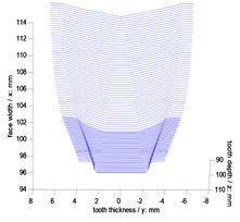
According to Eq. (7) to Eq. (9), a contact position and its cross section on face gears are shown in Fig. 2.
Fig. 2A contact position and its cross section on face gears
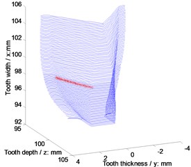
a) A contact position on face gears
b) Contact cross section on face gears
In Fig. 2, face gear tooth profiles on contact cross sections are modified involute profiles. Thus, based on contact viewpoints, face gear drives can be equivalent to involute gear drives. An equivalent face width of face gear teeth can be considered as the minimum diameter among long axles of contact ellipses of face gear drives. According to Hertz formulas [17], an equivalent face width of face gear teeth can be deduced as:
where is a loaded force, is Poisson ratio, is the elastic modulus, is a contact radius, and are elliptic integral factors.
2.4. Contact ratios of face gear drives
According to the proposed equivalent face gear drives as illustrated in Fig. 2, and the reference [18], contact ratios of face gear drives can be expressed as:
where is an addendum pressure angle, is a pitch pressure angle. According to the reference [18], addendum and pitch pressure angles can be written in:
where and are theoretical and operating center distances respectively. Thus, under the same conditions of drive ratios and installation distances, high contact ratio solutions of face gear drives can be constructed by three versions, namely increasing addendum coefficients, decreasing pressure angles of reference circles, and combination with the first methods, based on Eq. (11) to Eq. (13).
3. Simulation and analysis
3.1. Tooth geometry simulation
Geometric parameters of example cases of face gear drives are listed in Table 1. In addition, simulative face gear teeth are obtained, as shown in Fig. 3, and contact ratios of the example cases are calculated as listed in Table 2.
Table 1Geometric parameters of face gear drives
Symbol name | Values | Unit |
Number of pinion teeth | 24 | – |
Number of generative gear teeth | 25 | – |
Number of face gear teeth | 50 | – |
Module | 4 | mm |
Shaft angle | 90 | ° |
Addendum and Clearance coefficient and Pressure angle of standard version (without high contact ratio) | 1 / 0.25 / 20 | – / – / ° |
Addendum and Clearance coefficient and Pressure angle of first version | 1.2 / 0.25 / 20 | – / – / ° |
Addendum and Clearance coefficient and Pressure angle of second version | 1 / 0.25 / 16 | – / – / ° |
Addendum and Clearance coefficient and Pressure angle of third version | 1.1 / 0.25 / 18 | – / – / ° |
Table 2Contact ratios of the example cases of face gear drives
Types of face gear drives | Contact ratios |
Standard version | 1.78 |
First version | 2.08 |
Second version | 2.08 |
Third version | 2.07 |
According to the analysis of contact ratios in Table 2, standard version is a face gear drive with a normal contact ratio, and other three versions, namely first version, second version and third version, are face gear drives with high contact ratios, which are greater than two.
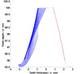
Fig. 3Simulations of face gear teeth
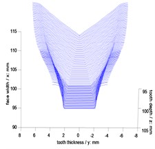
a) Standard version
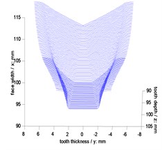
b) First version
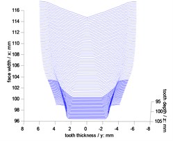
c) Second version
d) Third version
3.2. Dynamic behavior analysis
For the analysis of dynamic behaviors of these example cases, operating conditions and material characteristics of gears are listed in Table 3.
Table 3Operating conditions and material characteristics of gears
Symbols | Value | Unit | |
Operating conditions | Power | 7 | kW |
Input speed | 600 | r/min | |
Working temperature of oil | 80 | °C | |
Material parameters of gears | Poisson ratio | 0.3 | – |
Modulus of elasticity | 210000 | MPa |
Fig. 4Time-varying mesh stiffness of the example cases
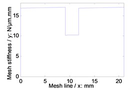
a) Standard version
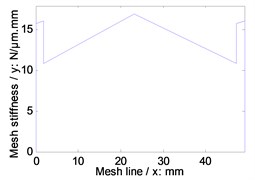
b) First version
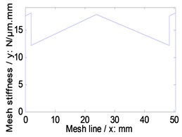
c) Second version
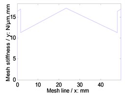
d) Third version
Simulations of time-varying and average mesh stiffness of face gear drives, which is based on the proposed tooth geometry modeling, are given in Fig. 4 and listed in Table 4, and static transmission errors under the operating conditions listed in Table 3, are calculated as shown in Fig. 5.
Table 4Average mesh stiffness of the example cases
Types of face gear drives | Average mesh stiffness | Unit |
Standard version | 15.4597 | N/μm.mm |
First version | 13.9722 | |
Second version | 15.2463 | |
Third version | 14.3884 |
Fig. 5Static transmission error of the example cases
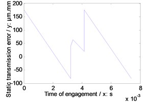
a) Standard version
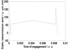
b) First version
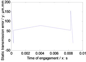
c) Second version
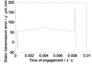
d) Third version
As illustrated in Fig. 4, Table 4 and Fig. 5, among three versions of face gear drives with high contact ratios, the best effect of decreasing average mesh stiffness is conducted by first version, and the best effect of decreasing maximum amplitude of static transmission errors is produced by second version.
Further, natural frequencies of each version are simulated in Fig. 6, gear dynamic responses and face gear dynamic mesh forces of each version are given in Fig. 7, and dynamic accelerations of bearings of each version are shown in Fig. 8.
In the case of Fig. 6 to Fig. 8, firstly, three versions of face gear drives with high contact ratios can improve vibrations of face gear drives effectively. Secondly, first version expresses a trend of increasing natural frequencies. Oppositely, second version shows that of decreasing natural frequencies, and the impact of second version on natural frequencies is greater than that by first version. Thirdly, mesh force of face gear drives would be reduced by three versions, and among three versions, the effect of second version on mesh force is best, and the impact of second version on mesh force is greater than that by first version. Furthermore, dynamic responses of bearings would be improved by three versions, specially in pinion bearings. However, the absolute difference among dynamic accelerations of bearings of three versions, which can be measured, is very small. Thus, although the effects of reducing vibrations of three versions of face gear drives with high contact ratios are excellent, which is the best among three versions is determined only by the analysis of dynamic behaviors is difficult.
Fig. 6Natural frequencies of the example cases
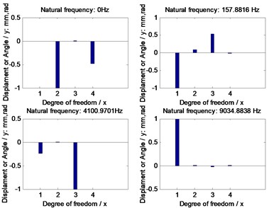
a) Standard version
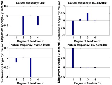
b) First version
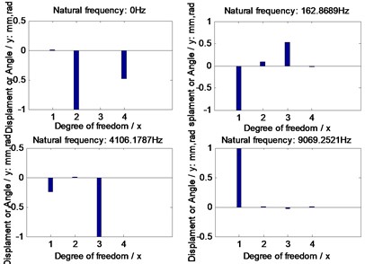
c) Second version
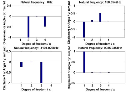
d) Third version
3.3. Strength analysis
Strength results of the example cases, which is based on ISO 6336 standard associated with the proposed equivalent face gear teeth, are calculated in Table 5.
Table 5Strength results of the example cases
Versions | Symbol name | Values | Unit |
Standard version | Bending stress of Pinion | 304.52 | MPa |
Bending stress of face gear | 295.75 | ||
Contact stress | 1176.3 | ||
Bulk temperature | 101.52 | °C | |
First version | Bending stress of Pinion | 283.61 | MPa |
Bending stress of face gear | 272.08 | ||
Contact stress | 1061.3 | ||
Bulk temperature | 111.19 | °C | |
Second version | Bending stress of Pinion | 344.40 | MPa |
Bending stress of face gear | 338.20 | ||
Contact stress | 1351.74 | ||
Bulk temperature | 134.67 | °C | |
Third version | Bending stress of Pinion | 324.37 | MPa |
Bending stress of face gear | 314.96 | ||
Contact stress | 1205.42 | ||
Bulk temperature | 119.35 | °C |
Fig. 7Dynamic behaviors
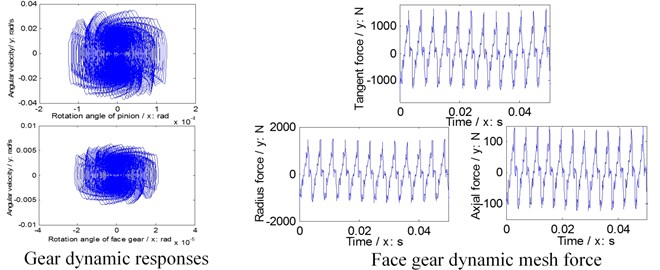
a) Standard version
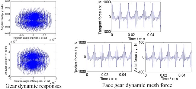
b) First version
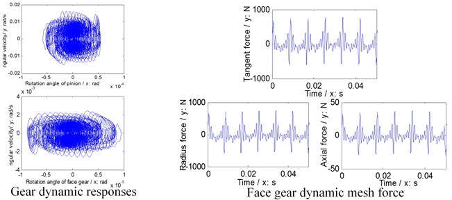
c) Second version
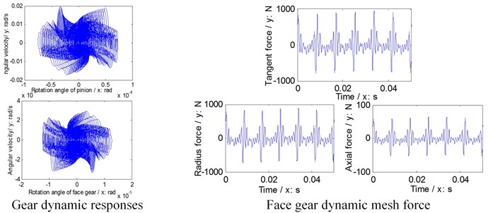
d) Third version
Fig. 8Dynamic accelerations of bearings
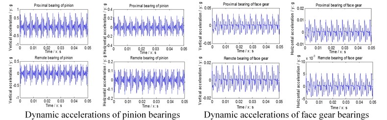
a) Standard version
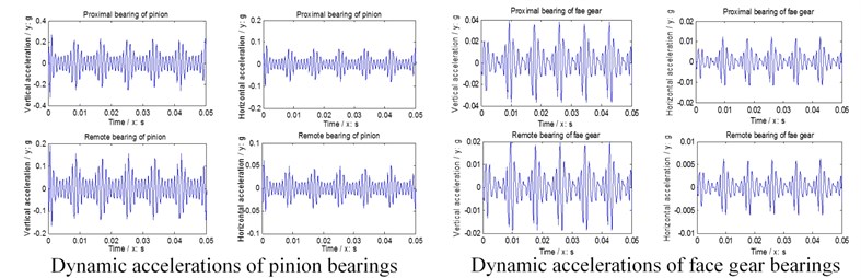
b) First version
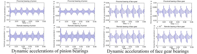
c) Second version
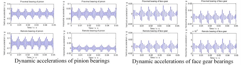
d) Third version
As illustrated in Table 5, first version would be benefit to decrease bending and contact stresses but not good for bulk temperatures. Second version would deteriorate strength of face gear drives. Third version indicates the impact of second version on strength is greater than that by first version.
According to comprehensive analysis of the dynamic behaviors and strength simulated in this issue, a result, which is three versions are effective for reducing dynamic responses of face gear drives, and the differences among three versions for dynamic behaviors of face gear drives are very small, but first version is better than other two versions for the strength of face gear drives, can be extracted. Thus, an optimization design solution of face gear drives with high contact ratios, which is the implementation of first version, namely increasing addendum coefficients of face gear drives, is recommended.
4. Conclusions
In the study, three important works can be extracted as follows:
1) Time-varying mesh stiffness and static transmission errors of face gear drives, which are based on the proposed face gear tooth modeling, are simulated, and dynamic behaviors of face gear drives with high contact ratios are discussed.
2) The strength of face gear drives with high contact ratios is investigated by ISO 6336 standard associated with the proposed equivalent face gear teeth.
3) An optimization design solution of face gear drives with high contact ratios is obtained by the comprehensive analysis of the dynamic behaviors and strength of the example cases simulated in this issue.
References
-
Litvin F., Bossler R., Chen Y.-J., Zhang Y., Wang J.-C. Design and geometry of face-gear drives. Journal of Mechanical Design, Vol. 114, Issue 4, 1992, p. 642-647.
-
Litvin F., Bossler R., Chen Y.-J., Lewicki D., Heath G., Wang J.-C. Application of face-gear drives in helicopter transmissions. Journal of Mechanical Design, Vol. 116, Issue 3, 1994, p. 672-676.
-
Litvin F. L., Egelja A., Tan J., Chen D., Heath G. Handbook on face gear drives with a spur involute pinion. DTIC Document, 2000.
-
Litvin F. L., Fuentes A., Howkins M. Design, generation and TCA of new type of asymmetric face-gear drive with modified geometry. Computer Methods in Applied Mechanics and Engineering, Vol. 190, Issue 43, 2001, p. 5837-5865.
-
Litvin F. L., Fuentes A., Zanzi C., Pontiggia M. Design, generation, and stress analysis of two versions of geometry of face-gear drives. Mechanism and Machine Theory, Vol. 37, Issue 10, 2002, p. 1179-1211.
-
Litvin F. L., Gonzalez-Perez I., Fuentes A., Vecchiato D., Hansen B. D., Binney D. Design, generation and stress analysis of face-gear drive with helical pinion. Computer Methods in Applied Mechanics and Engineering, Vol. 194, Issue 36, 2005, p. 3870-3901.
-
Barone S., Borgianni L., Forte P. Evaluation of the effect of misalignment and profile modification in face gear drive by a finite element meshing simulation. Journal of Mechanical Design, Vol. 126, Issue 5, 2004, p. 916-924.
-
Guingand M., De Vaujany J.-P., Jacquin C.-Y. Quasi-static analysis of a face gear under torque. Computer Methods in Applied Mechanics and Engineering, Vol. 194, Issue 39, 2005, p. 4301-4318.
-
Zanzi C., Pedrero J. I. Application of modified geometry of face gear drive. Computer Methods in Applied Mechanics and Engineering, Vol. 194, Issues 27-29, 2005, p. 3047-3066.
-
Frąckowiak P. Modelling and cutting a face-gear with straight line on CNC milling-machine. Manufacturing Engineering, Vol. 9, Issue 3, 2010, p. 19-21.
-
Frąckowiak P. Forming and geometrical dependences in the nom-homogeneous face-gear with involute line. Manufacturing Engineering, Vol. 9, Issue 4, 2010, p. 28-30.
-
Jin G., Zhu R., Bao H. Nonlinear dynamical characteristics of face gear transmission system. Journal of Central South University, Vol. 41, 2010, p. 1807-1813, (in Chinese).
-
Peng M., DeSmidt H., Saribay Z. B., Smith E. C. Parametric instability of face-gear drives with a spur pinion. Paper presented at the 2011 Annual Forum Proceedings – AHS International, 2011.
-
Saribay Z. B., Bill R. C., Smith E. C., Rao S. B. Elastohydrodynamic lubrication analysis of conjugate meshing face gear pairs. Journal of the American Helicopter Society, Vol. 57, Issue 3, 2012.
-
Hu Z. H., Tang J. Y., Chen S. Y., Lei D. C. Effect of mesh stiffness on the dynamic response of face gear transmission system. Journal of Mechanical Design, Vol. 135, Issue 7, 2013, p. 071005.
-
Wu C. H. Characteristic analysis on elastohydrodynamic lubrication of orthogonal face-gear. Advanced Materials Research, Vol. 912, 2014, p. 598-604.
-
Song L. M. Tooth Flank and Strength of Gear Drive. National Defence Industry Press, Beijing, 1987, (in Chinese).
-
Zhu X. Analysis of Load Capacity of Gears. Higher Education Press, Beijing, 1992, (in Chinese).
About this article

The authors are grateful for the financial support provided by the National Natural Science Foundation of China under No. 51105194 and No. 51375226, and the Fundamental Research Funds for the Central Universities, No. NS2015049.
Authors declare that there is no conflict of interests regarding the publication of this article.
