Abstract
A characteristic analytical method for the rubbing of aero-engine rotor blade-casing based on Hilbert Transform is proposed. The rotor experiment rig of aero-engine was used to simulate rubbing faults including single-point rub and local rub in the conditions of different casing thickness, different rubbing intensities, different rotational speeds and different rubbing positions. The casing acceleration signal was collected and subjected to the analysis by Hilbert envelope spectrum, and the result was compared with traditional spectrum analysis. The result indicates that the Hilbert envelope spectrum can effectively monitor the aero-engine running state in low frequency, and the method is more insensitive in sensor position, rotational speed, casing thickness and rubbing position. But the spectrum cannot efficiently monitor the aero-engine running state in low frequency.
1. Introduction
Tremendous economic loss and casualty were often caused by the rub faults of aero-engine. Now, a great many of scholars are studying on rubbing faults [1-9], and their research is mainly concentrated in rubbing characteristic analysis, rubbing experiment, rubbing fault diagnosis and rubbing positions identification. The study meets certain limitations owing to the complexity of rubbing fault, so it is difficult to be applied in practical aero-engine.
The accelerometer and speed sensor are often used to monitor practical aero-engineer vibrations state, and the monitoring frequency is not high. If we conduct direct spectrum analysis with the signal collected by sensors and the monitoring is only limited to low-frequency, we will often lose much effective information in high-frequency. Hilbert transform can obtain the complex envelope of signal which removes regular vibration component and only contains signal modulated information without the load frequency composition. According to the features that modulation frequency of signal is unavailable in normal operation of aero-engine; modulation frequency is complicated when local rubbing faults occur; modulation frequency is unique and understanding in single-point rub, a method of aero-engine rotor blade-casing rubbing characteristic analysis based on Hilbert transform is proposed. The experiment rig of aero-engine is used to simulate rub faults in condition of different casing thicknesses, different rubbing intensities, different rotational speeds and different rubbing positions. The casing acceleration signal is collected, analyzed and compared by Hilbert envelope spectrum and spectrum.
2. Hilbert transform [11, 12]
Suppose original signal is , then the Hilbert transform of is:
Structure analysis function :
Then obtain the amplitude function of , namely the Hilbert envelope spectrum:
3. Rubbing experiment
As traditional rubbing experiments do not fully consider the aero-engine rotor-disc-blade structure, they can be hardly applied to practical aero-engine [10]. In this paper, the aero-engine rotor experiment rig, designed by the Shenyang Aero-engine Design Institute, is used to simulate the single rubbing experiments and local rubbing experiments. The experiment rig core-engine is simplified to 0-2-0 support structure, and the compressor is simplified to single disk structure. In single-point rubbing, rubbing position was in turbine casing and different extents of single rubbing experiments could be embodied by adjusting rubbing screw against rubbing ring. By Adjusting local rubbing mechanism, we could embody different extents of local experiments at turbine and compressor ends. The rubbing intensity can be divided into two types: low and medium. Due to the limited space the rubbing intensity was selected randomly in different rubbing states, medium rubbing for single-point rubbing state, and low rubbing for local rubbing state. A thick wall turbine casing was processed in order to compare casing thickness to rubbing characteristic extract effect. The average thickness of thick wall turbine casing is 7 mm, but the average thickness of thin wall turbine casing is 4 mm. Fig. 1 is the experimental diagram before the installation of thick-wall casing and Fig. 2 is the experimental diagram after the installation of thick-wall casing. Installation positions of acceleration sensors for single-point rub and local rub include vertical upper, vertical lower, horizontal left and horizontal right. The rubbing positions are as follows: (1) single-point rub: (a) vertical upper, vertical lower, horizontal left and horizontal right when the turbine casing is thin wall, (b) upper right, lower right, upper left and lower left when the turbine casing is thick wall. (2) local rub: (a) the turbine casing local left or right, (b) the compressor casing local left or right. The experiments of single-point rubbing and local rubbing are show in Fig. 3-Fig. 8. The thin wall and thick wall casing rubbing experiments are show in Fig. 3 and Fig. 4.
Fig. 1Pro installed thick wall turbine casing
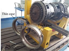
Fig. 2After installed thick wall turbine casing
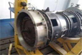
Fig. 3Thin wall turbine casing single-point rub experiment (1-rub spark 2-tighten bolt rub)
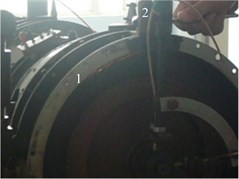
Fig. 4Thick wall turbine casing single-point rub experiment
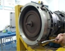
Fig. 5Thin wall casing local rub experiment
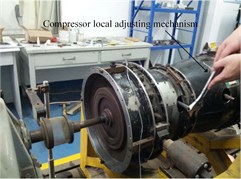
Fig. 6Thick wall casing local rub experiment
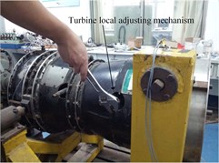
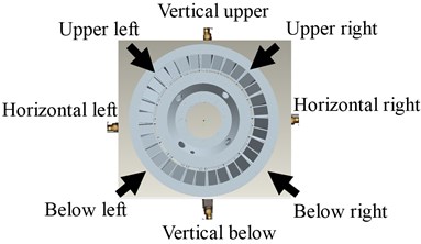
Fig. 5 and Fig. 6 are the experimental diagrams of local rubbing experiments for thin-wall and thick-wall casings. Rubbing position and accelerometer installed position on thin wall casing and thick wall casing are show in Fig. 7 and Fig. 8. All the rubbing experiments involved in the paper are basic on the acceleration signal collected by the acceleration sensors Model 4508 provided by Demark Brüel & Kjær.
Fig. 7Thin wall turbine casing single-point rub measuring and rub point
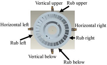
Fig. 8Thick wall turbine casing single-point rub measuring and rub point
4. Hilbert envelop spectrum analysis of casing measuring point
At present, the vibration state of actual aero-engine is usually monitored by accelerometer and speed sensor, and the monitored frequency is not high. As the frequency characteristics of acceleration sensors are completely the same in single-point rubbing and local rubbing, the amplitude is modulated by rotating frequency. There are modulated boundary frequencies in rubbing frequency and its frequency doubling. The rubbing frequency is equal with the blade numbers and the rotational speed product [10]. It is difficult to find in low frequency in state monitoring, because the boundary frequency usually is higher. The Hilbert transform can effectively extract the modulated frequency, thus the low frequency monitor can be implemented. The sensor installed position and the experiment rotational speed and the rubbing position are considered. The extract characteristics are compared between Hilbert envelope spectrum and spectrum.
4.1. Extracted characteristics comparison between spectrum and Hilbert envelope spectrum
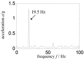
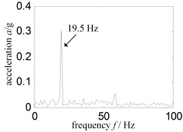
Firstly, taking the thin wall casing as example (the result is completely the same with thick wall casing), the extract characteristics are compared between spectrum and Hilbert envelope spectrum in low frequency. In this paper the low frequency range is 0 Hz-100 Hz. Randomly selected vertical upper of turbine casing as the impacting point of single-point rubbing and slightly inclined left of turbine casing as the impacting position of local rubbing, and then performed frequency spectrum and Hilbert envelope spectrum analysis basic on the signal collected by the sensors installed vertical upper turbine casing. Randomly selected the experimental data of April 29th, 2014, showing that rotational speed of aero-engine experiment rig is nearby 1170 r/min, the corresponding calculated rotational speed frequency is 19.55 Hz.
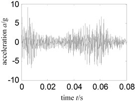
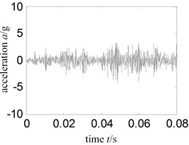
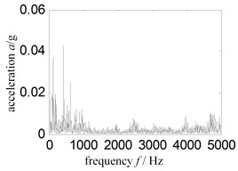
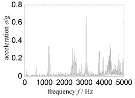
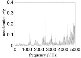
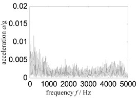
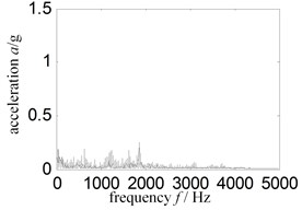
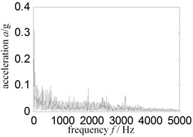
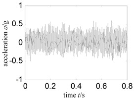
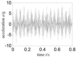
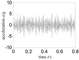
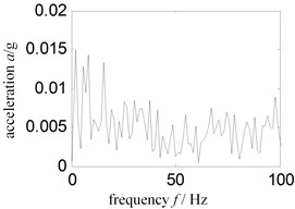
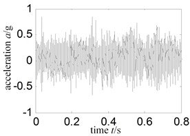
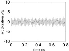
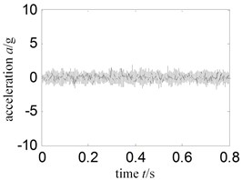
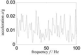
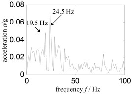
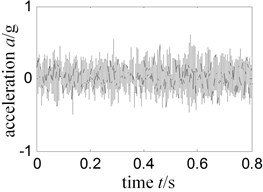
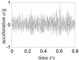
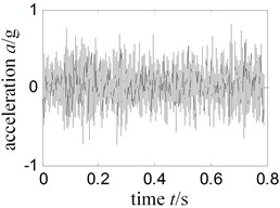
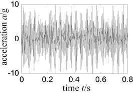
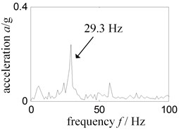
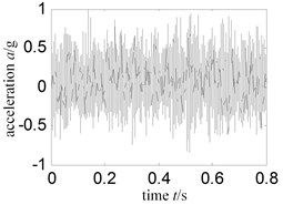
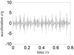
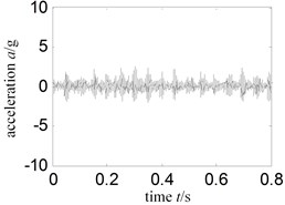
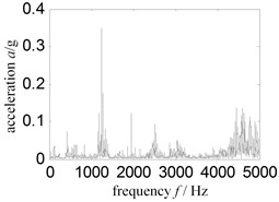
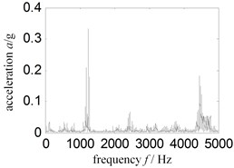
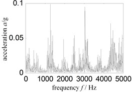
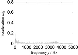
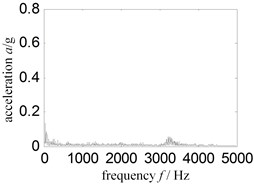
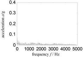
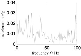
Fig. 9 and Fig. 10 shows the time-domain signal and amplified part of time-domain signal collected by the sensors installed above casing. Fig. 11 and Fig. 12 is the frequency domain signal and its amplification of Fig. 9. Fig. 9(a)-Fig. 12(a) shows the experimental status of experiment rig in normal status; Fig. 9(b)-Fig. 12(b) shows the experimental status of single-point rubbing; Fig. 9(c)-Fig. 12(c) shows the experimental status of local left.
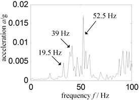
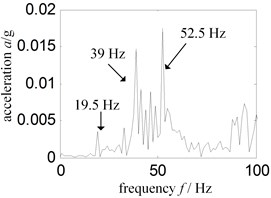
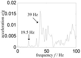
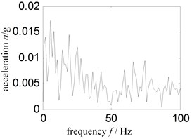
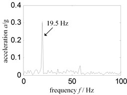
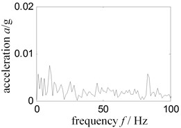
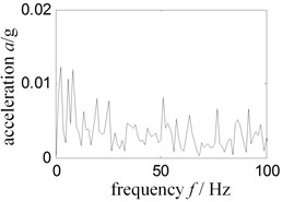
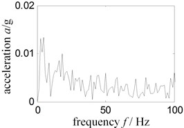
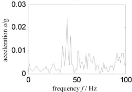
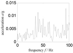
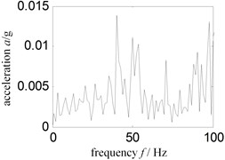
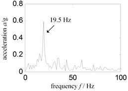
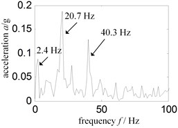
Comparison of Fig. 12(a)-(c) indicates that the characteristic frequency and spectrum amplitude of low-frequency in normal running, single-point rubbing and local rubbing is very close to each other. Therefore, the comparison result cannot effectively distinguish rubbing and its type. Analysis of above data with Hilbert envelope spectrum is shown below. Fig. 13 is the Hilbert envelope spectrum of Fig. 8; Fig. 14 is the local amplification of Fig. 13. Fig. 13(a)-Fig. 14(a) is the experimental status of experiment rig in normal running; Fig. 13(b)-Fig. 14(b) is the experimental status of single-point rubbing; Fig. 13(c)-Fig. 14(c) is the experimental status of local rubbing.
Fig. 9Time-domain signal-sensor installed turbine case vertical upper
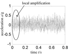
a) Normal
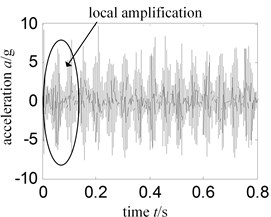
b) Single-point rub vertical upper
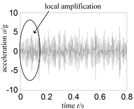
c) Local rub left
Fig. 10Time-domain signal local amplification – sensor installed turbine case vertical upper
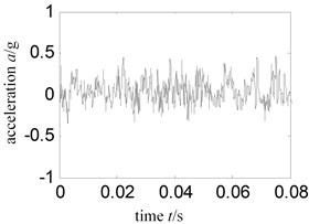
a) Normal
b) Single-point rub vertical upper
c) Local rub left
Fig. 11Spectrum-sensor installed turbine case vertical upper
a) Normal
b) Single-point rub vertical upper
c) Local rub left
Fig. 12Low frequency spectrum – sensor installed turbine casing vertical upper
a) Normal
b) Single-point rub vertical upper
c) Local rub left
From Fig. 14(a)-(c), we can draw conclusions as follows:
1) The Hilbert envelope spectrum is disorderly and the spectrum amplitude is small, when the experiment rig is in normal state.
2) Unique and outstanding modulated frequency exists in Hilbert envelope spectrum, when the experiment rig is running in single-point rub state. The modulated frequency is equal to the rotational speed frequency, and spectrum amplitude is about 75 times the value in normal state.
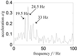
3) Complex and outstanding modulated frequency exists in Hilbert envelope spectrum when the experiment rig is running in local rub state. The rotational speed frequency exists but is not unique, which may be caused by non-single blade contacting with the rubbing ring, and modulated spectrum amplitude is about 20 times the value in normal state.
Thus, it can be seen that low frequency Hilbert envelope spectrum can effectively monitor the running state of the experiment rig.
Fig. 13Hilbert envelope spectrum – sensor installed turbine case vertical upper
a) Normal
b) Single-point rub vertical upper
c) Local rub left
Fig. 14Low frequency Hilbert envelope spectrum-sensor installed turbine case vertical upper
a) Normal
b) Single-point rub vertical upper

c) Local rub left
4.2. Effect of installation position of sensor on rubbing characteristics extract
Considering the influence of installation position of sensor on rubbing characteristics extract, we selected the experimental data collected in the same time with Section 4.1 for analysis, and conducted rubbing characteristic analysis on the signal collected by the acceleration sensors installed on the horizontal right of turbine casing and vertical upper of compressor casing, and then made a comparison with the signal collected by the acceleration sensor installed on the vertical upper of turbine casing. Fig. 15 shows the time-domain signal collected by the sensor of horizontal right and Fig. 16 is the Hilbert envelope spectrum of low frequency of Fig. 15. Fig. 17 is the time-domain signal collected by the sensor above compressor casing, and Fig. 18 is the Hilbert envelop spectrum of low frequency of Fig. 17. Fig. 15(a)-Fig. 18(a) is the experimental status in normal running. Fig. 15(b)-Fig. 18(b) is the experimental status of single-point rubbing while Fig. 15(c)-Fig. 18(c) shows the experimental status of partial rubbing.
From Fig. 16(a)-(c), and Fig. 18(a)-(c), we draw the following conclusions:
1) The Hilbert envelope spectrum is disorder in condition of the experiment rig is in normal running, which is consistent with Fig. 14(a).
2) When the experiment rig is running in single-point rubbing state, modulation frequency of Hilbert envelope spectrum has unique and outstanding components, being as rotational speed frequency; the amplitude of characteristic frequency is over 10 times the value in normal running, which is consistent with Fig. 14(b).
3) When the experiment rig is running in local left rubbing state, complex and outstanding modulated frequency can be observed in Hilbert envelope spectrum, which is consistent with Fig. 14(c).
4) The Hilbert envelope spectrum characteristics are consistent between the compressor casing and turbine casing, though the compressor casing is far away from the rubbing position.
Now, we can find that the Hilbert envelope spectrum can monitor the running state of experiment rig in low frequency, and it is insensitive for sensor installed positions.
Fig. 15Time signal-sensor installed turbine case horizontal right
a) Normal
b) Single-point rub vertical upper
c) Local rub left
Fig. 16Low frequency Hilbert envelope spectrum – sensor installed turbine case horizontal right
a) Normal
b) Single-point rub vertical upper
c) Local rub left
Fig. 17Time signal-sensor installed compressor case vertical upper
a) Normal
b) Single-point rub vertical upper
c) Local rub left
Fig. 18Low frequency Hilbert envelope spectrum-sensor installed compressor case vertical upper
a) Normal
b) Single-point rub vertical upper
c) Local rub left
4.3. Influence of rotational speed on rubbing characteristic extract
The practical aero-engineer operates on many speeds, so we need to consider the speed effect for rubbing characteristics extract. Select 3 types rotational speeds, 1000 r/min, 1500 r/min and 1700 r/min from 3 dates separately November 22th, 2011, May 4th, 2013 and July 27th, 2011. The rotational frequencies of these 3 speeds are 17.2 Hz, 25.4 Hz and 28.9 Hz separately. We conducted Hilbert envelope spectrum analysis on data collected by the acceleration sensors installed turbine casing vertical upper. Experiment state is single-point rub (taking rub position on horizontal right of turbine as an example) and normal running of experiment rig. Rubbing state, rubbing position and installation position of sensor was selected randomly.
Fig. 19Time signal – experiment rig normal running
a) Rotational speed 1021 r/min
b) Rotational speed 1512r /min
c) Rotational speed 1737 r/min
Fig. 20Low frequency Hilbert envelope spectrum-experiment rig normal running
a) Rotational speed 1021 r/min
b) Rotational speed 1512r /min
c) Rotational speed 1737 r/min
Fig. 21Time signal-experiment rig running single rub horizontal right
a) Rotational speed 1021 r/min
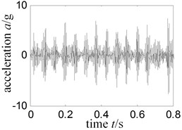
b) Rotational speed 1512r /min
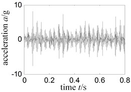
c) Rotational speed 1737 r/min
Fig. 22Low frequency Hilbert envelope spectrum-experiment rig running single rub horizontal right
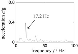
a) Rotational speed 1021 r/min
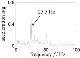
b) Rotational speed 1512r /min
c) Rotational speed 1737 r/min
Fig. 19 shows the time-domain signal in normal running state; Fig. 20 is the envelope spectrum related with Fig. 19; Fig. 21 represents single-point rubbing time signal, and the Fig. 22 represents Hilbert envelope spectrum related with Fig. 21. Speed being 1000 r/min in Fig. 19(a)-Fig. 22(a), speed 1500 r/min in Fig. 19(b)-Fig. 22(b), speed 1700 r/min in Fig. 19(c)-Fig. 22(c).
From Fig. 20 and Fig. 22, we can draw the following conclusions: under the three different rotational speeds, low-frequency Hilbert envelope spectrums have the same characteristics with the speed 1200 r/min, namely: the rotational speed has no effect on rubbing characteristics extracted.
4.4. Influence of casing thickness and rubbing position on rubbing characteristics extract
To analyze the influence of casing thickness and rubbing position on rubbing characteristics, we replaced the thin turbine casing with thick turbine casing whose thickness is 7 mm; single-point rubbing position with right upper, right lower, left upper and left lower of turbine casing. As limited by the length of paper, we took the right upper of casing for single-point rubbing and left inclined for local rubbing as example to analyze the signal collected by the acceleration sensors vertical upper of turbine casing. Fig. 23 indicates the time-domain signal collected by sensor above; Fig. 24 and Fig. 25 is the frequency spectrum and low-frequency spectrum corresponding to Fig. 23; Fig. 26 and Fig. 27 is the Hilbert envelope spectrum and low-frequency Hilbert envelope spectrum corresponding to Fig. 23.
Fig. 23Tickness turbine case time signal-sensor installed turbine case vertical upper
a) Normal
b) Single-point rub vertical upper
c) Local rub left
Fig. 24Thickness turbine case frequency spectrum-sensor installed turbine case vertical upper
a) Normal
b) Single-point rub vertical upper
c) Local rub left
Fig. 25Thickness turbine case low frequency spectrum-sensor installed turbine case vertical upper
a) Normal
b) Single-point rub vertical upper
c) Local rub left
From Fig. 25 and Fig. 27, we found: spectrum and Hilbert envelope spectrum characteristics are the same between thick wall casing and thin wall casing. Namely, the casing thickness and rubbing position has no effect on extract rubbing characteristics. In low frequency, Hilbert envelope spectrum can effectively monitor the running state of aero-engineer, but spectrum cannot do it.
Fig. 26Thickness turbine case Hilbert envelope spectrum-sensor installed turbine case vertical upper
a) Normal
b) Single-point rub vertical upper
c) Local rub left
Fig. 27Thickness turbine case low frequency Hilbert envelope spectrum-sensor installed turbine case vertical upper
a) Normal
b) Single-point rub vertical upper
c) Local rub left
5. Conclusions
In considering that accelerometer is often used to monitor the vibration state in practical aero-engine, and the convenience of engineering application, we proposed the characteristic analytical method for the rubbing between rotor blade and casing of aero-engine based on Hilbert transform. This method showed high sensitivity, and can judge if aero-engine has rubbing by simple Hilbert envelope spectrum analysis on signal in low and medium rubbing state.
Under different states in the experiment, low-frequency Hilbert envelope spectrum shows that in normal running of experiment rig, there is no obvious characteristic frequency; single-point rubbing shows unique and significant rotational speed frequency; local rubbing shows significant rotational speed frequency, but the frequency is not unique.
The method also have the following characteristics:
1) Insensitive to installation position of sensor. No matter the sensor is installed vertically or horizontally on turbine casing, or on compressor end, it can effectively monitor the motion state of aero-engine.
2) The rotational speed has no effect on extraction of rubbing characteristics. In four different rotational speeds, the method has the same feature.
3) The casing thickness and rubbing position has no effect on extraction of rubbing characteristics. There are same feature between the thick wall casing and thin wall casing. The different rubbing positions have good consistency.
4) The method is convenient in engineering practical application, because it requires no additional equipment and instruments in collecting and processing the signal.
The method should require further study in terms of the following aspects:
1) Rubbing intensity. The low and medium rubbing experiment were simulated and researched, but the serious rubbing was not yet considered. The extracted characteristics effectiveness by the Hilbert transform method should be taken into consideration for serious rubbing state.
2) The proposed research method in this paper should be inspected in the actual project. The proposed method was inspected just by simulated rubbing faults data of the rotor experiment rig of aero-engine. As the real aero engine structure is far more complex than rotor experiment rig as well as a lot more external noises and vibrations existing in real flight, actual project inspection is required to determine the efficiency of extracting casing characteristics.
References
-
Tian Yong-Wei, Yang Jian-Gang Analysis on coupled vibration of rotating machinery in case of rotor to stator rub. Journal of Mechanical Engineering, Vol. 46, Issue 7, 2010, p. 102-107.
-
Li Chao-Feng, Li He, Ma Hui, et al. Bifurcation and stability of the flexible rotor-bearing system with rub-impact by a continuum model. Journal of Mechanical Engineering, Vol. 46, Issue 11, 2010, p. 107-113.
-
Ma Hui, Yang Jian, Song Rong-Ze, et al. Review and prospect on the research of rub-impact experiment of rotor systems. Journal of Vibration and Shock, Vol. 33, Issue 6, 2014, p. 1-12.
-
Chen Guo, Li Cheng-Gang, Wang De-You Rotor-stator rubbing fault diagnosis knowledge acquisition using rule extraction from neural networks. Acta Aeronautica et Astronautica Sinica, Vol. 29, Issue 5, 2008, p. 1319-1325.
-
Yu Ming-Yue, Chen Guo, Liu Yong-Quan, et al. Aero-engine rotor-stator rubbing position identification based on casing strain signals. Acta Aeronautica et Astronautica Sinica, Vol. 34, Issue 6, 2013, p. 1474-1484.
-
Hongliang Yao, Qingkai Han, Lingxun Li, et al. Detection of rubbing location in rotor system by super-harmonic responses. Journal of Mechanical Science and Technology, Vol. 26, Issue 8, 2012, p. 2341-2437.
-
Li Yun-Gong, Zhang Hua-Biao Signature extracting method of the fault of rubbing rotor based on measured impulse response. Chinese Journal of Mechanical Engineering, Vol. 43, Issue 4, 2007, p. 224-228.
-
Chen Guo, Liu Yong-Quan, Jiang Guang-Yi, et al. A novel method for identifying rotor-stator rubbing positions using the cepstrum analysis technique. Journal of Mechanical Science and Technology, Vol. 28, Issue 9, 2014, p. 3537-3544.
-
Yu Ming-Yue, Chen Guo, Li Cheng-Gang, et al. Rotor-stator rubbing positions identification of aero-engine based on wavelet packet analysis and support vector machine. Journal of Aerospace Power, Vol. 28, Issue 1, 2013, p. 46-53.
-
Chen Go, Feng Go-Quan, Jiang Guang-Yi, et al. Characteristic analysis and verification of casing vibration acceleration for aero-engine blade-casing rubbing fault. Aero Engine, Vol. 40, Issue 1, 2014, p. 10-16.
-
Zhang Shuai, Yang Yong, Han Qing-Kai, et al. Experimental study on a rotor system with rub-impact at fix limiter based on HHT. Journal of Vibration and Shock, Vol. 29, Issue 7, 2010, p. 121-125.
-
Lei Ya-Guo Machinery fault diagnosis based on improved Hilbert-Huang transform. Journal of Mechanical Engineering, 2011, Vol. 47, Issue 5, p. 71-77.
About this article

