Abstract
The complicated temperature environment of the high-speed rail bearing will generate the thermal stress and thermal deformation, which will change the vibrational characteristics of the bearing. If the vibration is serious, it will result in bearing failure and destructive accidents. Thus, the steady temperature field and the relationship between temperature field and the critical speed of the bearing were researched based on the vibrational characteristics in the paper. According to the specific work conditions and structure characteristics of the double row tapered roller bearing assembly, the heat transfer model of high-speed rail bearing was developed. The heat source and the external heat dissipation of the bearing were calculated, the reasonable boundary conditions of lubrication were set, and then the finite element model was established in ANSYS. According to four different distribution methods of heat source, the temperature field of the inner ring, outer ring and rollers were simulated and analyzed. Comparing the four different results, a reasonable distribution method of the heat source was put forward. Finally the effects of steady temperature field on critical speed of high-speed rail bearing were discussed. The simulation results showed that the bearing temperature distribution was basically consistent with the actual working conditions. The steady temperature field has stronger effect on vibration mode of low-order critical speed then high-order critical speed of bearing. The results of this study provide a basis of vibration characteristics for the use and optimal design of high-speed rail bearing.
1. Introduction
For the research on the vibration characteristics of rotor-bearing system, the bearing temperature is widely assumed as constant, that is to say the vibration characteristics of bearing is independent of temperature distribution [1]. However, for the high-speed rail bearing, when the bearing works at high speed and with heavy load, the temperature along the axial and circumferential radial direction has the characteristics of multi-stage distribution, and it changes with time, due to each component of the bearing having the difference working performance [2]. The complicated temperature environment makes the bearing producing structural deformation and triggering a variety of exciting force, which affects the vibration characteristics of the bearing. Besides material physical parameters (i.e. elastic modulus) will change with different temperature, which will also have certain influence on vibration characteristics [3-4]. Therefore, in order to identify the sensitive parameters affecting the thermal vibration characteristics of bearing, it is necessary to study the steady temperature field of high-speed rail bearing.
The research on the effects of steady or transient temperature field on vibration characteristics of bearing is little. Generally, people use thermal network method or the finite element method. Pouly [5] and Nicolas [6] analyzed the steady-state temperature field of bearing using thermal network method. But this method must solve a large number of equations, and can only get the discrete data of bearing temperature.
The finite element method have many characteristics, such as the unit division is flexible, the finite element model and structure model is uniform, and it can solve the overall temperature field of the parts. In the numerical simulation of the bearing thermal vibration characteristics by finite element method, researchers need to solve several key questions, such as calculation and distribution mode of heat source, definition of boundary constraint conditions and so on. Lee et al. [7] obtained the temperature distribution, temperature rise and thermal deformation of the spindle system as affected by different rotation speeds. The relationship between thermal deformation and vibration during rotation of high-speed spindle for machine tools through vibration test was researched. Varela et al. [8] presented the thermal behavior of a tilting-pad journal bearing operating under controllable regime, considering the parameters: oil film temperature field, resulting forces over rotor and pads, and rotor equilibrium position. Tarawneh et al. [9] built the finite element thermal model of the railroad tapered-roller bearing to simulate different heating scenarios with the purpose of obtaining the temperatures of internal components of the bearing assembly, as well as the heat generation rates and the bearing cup surface temperature. Holkup et al. [10] presented a finite element method based on thermo-mechanical model of spindles with rolling bearings, which predicted temperature distribution and thermal growth, bearing stiffness and contact loads under specified operating conditions.
In this paper, according to the external structure of high-speed rail bearing system, including the axle box’s position of double row tapered roller bearing, the inner and outer diameter of the bearing pedestal, the air velocity outside the bearing pedestal and the shaft structure, the complex heat transfer process of bearing system was simplified into heat transfer model of the single bearing. Then the thermal parameters of lubricating grease were predicted and the boundary conditions of lubrication were determined. Four different distribution method of heat source were designed. Combined with the calculations of heat source and heat dissipation, the temperature field of high-speed rail bearing was finite element simulated, and the four different results were analyzed. Then a heat source distribution method that the heat was unevenly distributed on the roller and the inner and outer rings was put forward. And then the effects of steady temperature field on critical speed of high-speed rail bearing were discussed by the finite element simulation. The results of the temperature field and vibration characteristics were consistent with the actual experimental results when the bearing works. Therefore, the finite element simulation method can provided a basis for vibration characteristics and optimal design of the bearing.
2. Physical models
This paper took a research on the double row tapered roller bearing used in high-speed rail. We used SolidWorks to establish the bearing structure model with the dimensions of 130 mm×230 mm×160 mm. Each row of the bearing has 21 rolling element. The structure model and the basic parameters were shown in Fig. 1 and Table 1. Based on the hypothesis of Hertz contact stress [11-12] and the principle of effectiveness of contact guarantee, we made the following assumptions in modeling: 1) We omitted the chamfer and edge of the entity; 2) The rolling element, inner and outer ring and the cage were all the linear elastic material; 3) The rolling elements were rollers with a straight line generatrix, and its contact area with the inner ring was line.
Under different loading, the contact area of the bearing is different. Based on the Eq. (1) of elastic mechanics, we can obtain the half width () of the contact area between roller and inner and outer rings under certain loading. According to the numerical range of 2 we can respectively divide the surface in the roller, the inner and outer rings, so as to establish the contact area:
In the formula, is the sum of principal curvature of the two contact bodies at the contact point. is the total load; is the cylinder length of the roller; is the contact half width. Under the radial load of 70 KN, the contact half width of the inner ring () is 1.5 mm, the contact half width of outer ring () is 0.71 mm.
Fig. 1The structure model of High-speed rail bearing

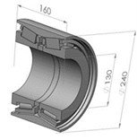
Table 1The basic parameters of the bearing
The basic parameters of the bearing | |
Nominal diameter | 130 mm |
Nominal outer diameter | 240 mm |
Pitch circle diameter | 168.8 mm |
Width | 160 mm |
The number of the rollers | 42 |
Roller diameter | 28 mm |
Roller length | 45 mm |
Modulus of elasticity | 207 GPa |
Poisson’s ratio | 0.3 |
3. Mathematical model
3.1. Heat transfer model of bearing
In the bearing system, the outer ring of the bearing is in contact with the bearing pedestal, the inner ring and the shaft are interference fit, and finally heat is dissipated through the thermal convection between the bearing pedestal, the shaft and the air. In the bearing internal, grease forms the oil film in the clearance between the roller and the inner and outer ring. We must consider the role of oil film to accurately construct heat transfer model of bearing [13]. Our new method is to consider the shaft, the bearing pedestal and the bearing as a system. Then we simulated the oil film situation in FLUENT when the roller was moving. We put it as the boundary conditions of the steady temperature field, and then we can load the heat source, so as to obtain the temperature field of the whole bearing system.
However, according to Eq. (2) of minimum oil film thickness, which was put forward by Dowson and Orcutt in 1967:
Grease thickness in the flow field is too thin to model or divide mesh in the finite element solution process. In addition, when the mesh is not fine enough, it is likely to be occurred the penetration of the oil film. Moreover, there was little effective information on the thermal properties of lubricating grease, for the relevant research is few. Even with this precondition, the motion of the oil film between the roller and the raceway of is very complex. If we only load the rotation speed, it is impossible to correctly describe the motion state and friction state of oil film in the lubrication condition [14].
In view of this, according to the working condition of the high-speed rail bearing and the parameters of bearing system, we calculated the heat flow instead of the heat dissipation of bearing pedestal, bearing and shaft. We loaded the convective coefficient on the working surface. The convection occurred in the bearing seat, the shaft and the oil film, relative to the bearing. We transformed the temperature field research of the bearing system into the temperature field research of the single bearing. Finally we built the heat transfer model of bearing (Fig. 2). Based on the model, we can calculate the heat source, the boundary conditions and the heat dissipating capacity in the following paragraphs.
Fig. 2The heat transfer model of the bearing
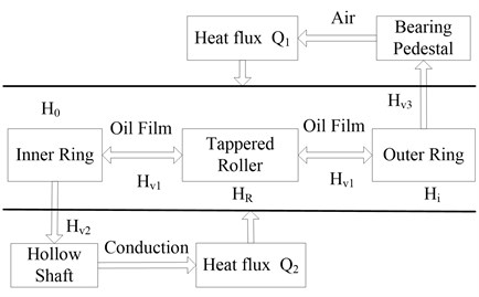
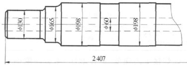
Fig. 3The axle of bogie in CRH2 EMU
3.2. Calculation of the heat source
The research content of bearing temperature field mainly includes generating heat, heat transfer and heat dissipation. According to the principle of conservation of energy, within a certain time the loss power of bearing friction will be converted to heat. Thus we must first calculate the friction torque of the bearing so as to calculate the heat value of bearing. When the train brakes or in other abnormal conditions, we must also take the effect of thermal radiation of wheel into account [15]. This paper only considered that the train smoothly runs. In general, the friction of rolling bearing is composed of the following parts:
1) Pure rolling friction caused by the elastic hysteresis;
2) Sliding friction caused by the sliding of rolling contact surface;
3) Friction caused by spin sliding at the normal direction of the contact surface;
4) Pure sliding friction on the sliding contact surface;
5) Viscous friction of the lubricant (mainly grease).
For the calculation of heat source, the empirical formulas were relatively mature, which mainly based on Palmgreen’s formulas summarizing all kinds of experiments. Resistance torque of tapered roller bearings mainly were the sliding friction torque between the surface of the rolling element and the inner and outer ring, as well as the sliding friction torque between the section of rolling element and nested large flange. Witte gave the friction torque Eq. (3)-(9) of tapered roller bearings under different radial and axial loads [16]:
In the equations, is the friction resistance moment only applied the radial load; is the friction resistance moment only applied the axial load; is the radial load; is axial load; is the variable of sliding friction; is the friction coefficient; is the pressure angle; is the power at high temperature. is the speed; is the average diameter of the bearing.
When the train runs smoothly, the two bearings in the axle are loaded by the 25 KN. According to the bearing parameters, we can calculate 187.8 mm, 1240943.003, 529 639.6 N·mm, 4811.80 N·mm, 173 79.366 W.
3.3. Calculation of the boundary conditions of grease
The axle box bearings of CRH3 train used lithium grease named Shell Nerita HV L218 from Shell Group of Companies. The kinematic viscosity of the grease is 42 mm2/s at 40° and 8 mm2/s at 100°. The base oil is XHVI synthetic oil which is manufactured by is omerization of soft wax for the company’s unique. In the current research on temperature field, few tests on the thermal convection parameters and the thermophysical parameters. In the recent paper, the aviation lubricating oil MIL-L 7808 is the most frequently-used medium in the hydrodynamic lubrication model. The thermophysical parameters are shown in Table 2.
Table 2The thermophysical parameters of MIL-L 7808
Temperature (°C) | Specific heat capacity (KJ/Kg·°C) | Viscosity-pressure coefficient (10-8 Pa) | Kinetic viscosity (mm2/s) |
50 | 1.92 | 1.075 | 38.34 |
100 | 2.06 | 0.758 | 8.618 |
As can be seen, there is little difference on kinematic viscosity between MIL-L-7808 and Nerita HV L218 at the working temperature of 40°C-80°C, but the kinematic viscosity of lithium grease is gradually decreased with the increase of temperature, the relationship is showed in Eq. (10) [17]:
In the Eq. (10), is the kinematic viscosity when contact half width is ; is the temperature when the contact half width is ; is the reference temperature; is the reference kinematic viscosity; is the conversion coefficient. According to this Eq. (10), we set the kinematic viscosity of the grease is about 36 mm/s.
The solving process of the convective heat transfer coefficient of the lubricating grease is:
In Eqs. (11)-(13), is the convective heat transfer coefficient; is the Reynolds coefficient; is viscosity; is outer diameter; is the inner ring width of bearing.
Combined data with the actual situation, the lubricant density is between 0.85 g/cm-3 and 0.91 g/cm-3, the thermal conductivity is between 0.01 W/m·K and 0.02 W/m·K, the specific heat capacity is between 187 J/Kg·°C and 240 J/Kg·°C. Then we can calculate the convective heat transfer coefficient of the grease () is about 1 e-5 W/K.
3.4. Calculation of the external heat dissipating capacity
The heat dissipation of bearings pedestal and shaft is in the form of heat flux. It happens on the external of the outer ring and the inside of the inner ring. According to the test results obtained by the actual conditions, roller temperature is about 80°C, the outer ring temperature is higher than the inner ring temperature. So the difference in temperature between bearing seat and external environment is set 40°C, the temperature difference between inner ring and shaft is set 30°C.
Fig. 3 is an axle of the trailer bogie in CRH2 EMU. The axle is a hollow shaft, made of alloy steel material. The hollow diameter is 60 mm, the part of 130 mm is matched with bearing pedestal. Thus the convection coefficient between the shaft and the bearing () is determined by the thermophysical parameters of the hollow shaft material. According to the information from SKF and the structure parameters of the bearing pedestal [18], the maximum thickness of the bearing pedestal is about 50-60 mm at a rough estimate. Combined with the axle box parameter of high-speed rail EMU, the bearing pedestal diameter is preselected 215-277 mm.
Simplified the bearing pedestal and the shaft into a cylinder, we can calculate the heat dissipating capacity using the heat conduction equation of the cylinder:
In Eq. (14), is heat dissipating capacity; is the thermal conductivity of the material. The thermal conductivity of aluminum is 173 W/mK, the thermal conductivity of alloy steel is 52 W/mK; is the change of temperature; is the outer diameter of bearing pedestal; is the inner diameter of bearing pedestal. Then we can calculate the external heat dissipating capacity of bearing system, 7728 W, 8400 W.
4. Finite element simulation and discussion
4.1. Finite element model
The structure model in SolidWorks is imported to ANSYS. For the high-speed rail bearings, rolling elements and the inner and outer rings are made of structural steel. Space ring is made of aluminum alloy. The material of cage is polyimide. Using the free mesh in ANSYS, the mesh is more compacter in the contact area between the roller and the inner and outer rings. The mesh size is 2 mm. The model can be divided into 317935 nodes, 215126 units.
The thermal analysis procedure in finite element solution is basically consistent with the theory calculation, including loading the heat source, setting the boundary conditions and setting the external heat dissipating capacity. Thus based on the heat transfer model and the theoretical calculation results, the heating areas between the roller and the inner and outer ring applied the heat flux. According to the following surface area of the heat source shown in Table 3, the total heat is distributed to each component, and the heat of unit temperature and unit area is calculated. The boundary conditions applied the thermal convection. The heat dissipation of inner and outer ring applied the negative heat flow.
Table 3The heating areas of the bearing
Heat source | Roller | Outside of inner ring | Inside of outer ring |
Heating areas / mm2 | 3252.79 | 22796.77 | 36557.92 |
4.2. Finite element simulation and discussion
Distribution of heat source is always a difficult problem in finite element method to solve the bearing temperature field. One reason is the relevant theoretical research is relatively less, because the heat between the roller and the raceway not only involves the adhesion friction, but also involves a series of contact theory of the lubrication which is still in researching; another is the internal space of the crankcase is very compact, usually the grease occupies 1/3-1/2 internal space of the whole space, so the temperature sensor is not easy to be placed, thus the inside temperature of the bearing can’t be obtained [19]. All these are difficulties to distribute the heat source.
This paper summarizes four different distribution solutions of heat source: roller and inner ring are the heat source (Solution 1); the inner and outer rings are the heat source (Solution 2); heat evenly distributes on the roller and the inner and outer rings (Solution 3); heat is not unevenly distributed in the inner and outer rings (Solution 4). The results is showed in Table 4. We discussed in detail in the following paragraph.
Table 4The comparison of four distribution solutions of heat source
Distribution solutions of heat source | Heat source | The simulation result of the temperature distribution | ||
Inner ring | Roller | Outer ring | ||
Solutions 1 | √ | √ | The temperature of inner ring is higher the outer ring. | |
Solutions 2 | √ | √ | The roller temperature is gradually reduced from outside to inside. | |
Solutions 3 (heat evenly distributes) | √ | √ | √ | The contact area of the roller and cage is at the highest temperature. |
Solutions 4 (heat unevenly distributes) | √ | √ | √ | The contact area of the roller and rings is at the highest temperature. |
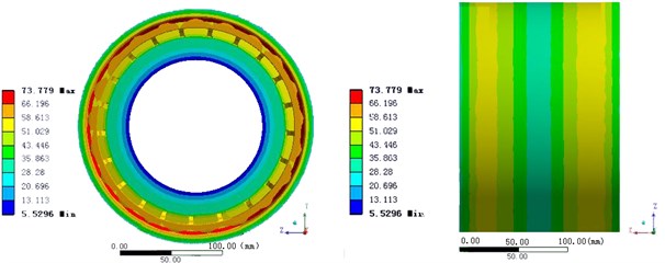
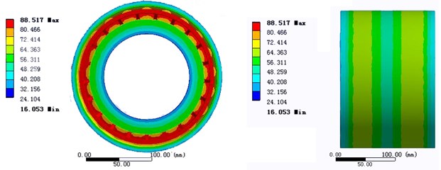
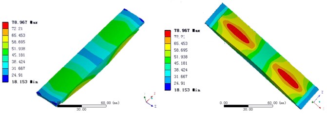
Fig. 4The temperature distribution of three solutions
a) Solution 1
b) Solution 2
c) Solution 3
Solution 1 is the traditional loading method, which considers the roller and inner ring as the heat source [20]. The results show that the contact area of roller and the inner ring has the highest temperature and the temperature of the roller is lower, shown in Fig. 4(a). Thus the temperature of the inner ring is higher than that of the outer ring, which is also verified the Pam Green method is not suitable for the temperature field of bearing under the condition of high speed rail.
Solution 2 considers the inner and outer ring as the heat source. The advantage of the method is that it can make the steady state temperature of the roller highest. However the friction between roller and inner and outer ring in the actual operation will make that heat can’t completely dissipate into inner and outer ring. So the temperature of the roller from outside to inside gradually reduces (Fig. 4(b)). Because of the lack of strict theory, this solution is also inapplicable.
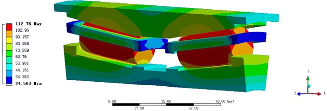
Solution 3 considers the roller and inner and outer ring as the heat source. The heat evenly distributed to roller and inner and outer ring. The reason is the rotation of the roller around the axis in the high-speed operation will also generate heat. In the steady state, the surface temperature of inner and outer raceway is little difference. So the roller and inner and outer ring can be approximated as a constant temperature state. But the simulation results showed that the temperature of the contact area between the roller and cage is the highest. In other words, the heat transfers from the two sides of the roller to the inner and outer rings (Fig. 4(c)).
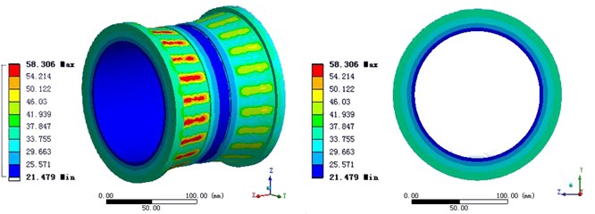
Fig. 5The simulation result of Solution 3
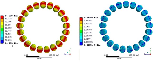
a) The temperature distribution and heat flux of roller
b) The temperature distribution and heat flux of inner ring
There are two reasons: the heat transfer of roller and the inner and outer raceway is heat conduction, and the heat transfer between the roller and cage is thermal convection. At the same time, for the heat of the same value, the heat dissipation between the roller and the raceway though the heat conduction is faster. Besides in the actual process, roller surface adheres to a layer of grease. Although the convection coefficient of grease was equivalently applied on the surface of the roller and the raceway, the heat of the grease absorbed by its own wasn’t taken into account. According to the lubrication mechanism of rolling bearing, grease has the effect of sealing and lubrication both. This property of the grease can absorb excess heat of roller surface. But due to the particularity of grease in the heat transfer process, it does not take into account in the finite element modeling.
The bearing temperature distribution of Solution 3 is close to the actual situation, but temperature distribution of the heat source is still unsatisfactory. Fig. 5 is the temperature distribution and heat flux of roller and inner ring in Solution 3.
Solution 4 also considers roller and inner and outer ring as the heat source, but the heat is unevenly distributed on the roller and the outer ring. The difference from the Solution 3 is in modeling. Solution 4 considers the contact area between rollers and the inner and outer raceway will generate heat, so the temperature of contact area is higher than that of noncontact area. Fig. 6 shows how to distribute the heat source.
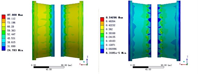
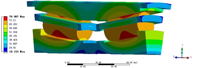
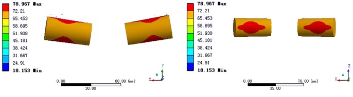
Compared the simulation result of Solution 4 with Solution 3 in Fig. 7, we can find in Solution 4, the temperature of the contact areas between the roller and the raceways is the highest, and the temperature of the roller reduces continuously from the contact areas to both sides, through the heat transfer of the inner and outer rings. However in Solution 3, the contact areas between the roller and the cage are always the heat source, no matter how to modify the heat source.
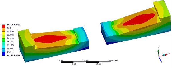
The actual heating experience and the final simulation result of Solution 4 had well consistency. In other word, the heat transfers from the contact area of roller and the inner and outer raceway to raceways, and heat dissipates through the outer surface of the inner ring and the inner surface of the outer ring. Fig. 8 shows the temperature distribution of the roller, the inner and outer rings and the cage.
Fig. 6The conditions of loading in Solution 4
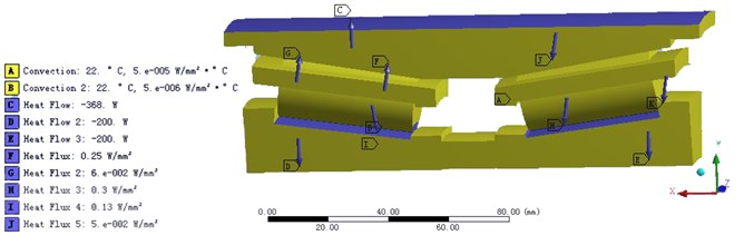
Fig. 7Compare the temperature distribution of Solution with Solution 4
a) Solution 3
b) Solution 4
The effects of steady temperature field on vibration characteristics of bearing mainly result from two aspects: one is the decrease of elastic modulus of the material; the other is the stiffness variation induced by the heat stress because of the temperature gradient [21]. With respect to the variation of the elastic modulus and the coupling variation of elastic modulus and thermal stress (hereafter called coupling variation), the effects of the two aspects on the critical speed is discussed in this paper. When the variations of radial temperature are different, the effects of elastic modulus on critical speed of the bearing are shown in Table 5, while the effects of coupling variation on critical speed are shown in Table 6.
Fig. 8The temperature distribution of the bearing in Solution 4
a) The inner ring
b) The outer ring
c) The roller
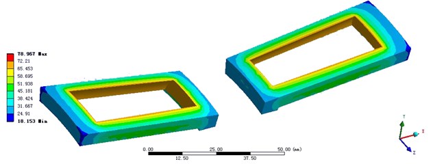
d) The cage
As can be seen from the Table 5 and Table 6, with the increase of the radial temperature difference of the bearing, the critical speed decreases gradually, and the variation is nonlinear. By comparison, the effect of coupling variation on the critical speed is larger than the effect of elastic modulus. Therefore, the influence of thermal stress on critical speed plays a leading role. In addition, it is found that the higher the order is, the less the critical speed reduces, when the radial temperature difference increases.
Table 5The effects of elastic modulus on critical speed with different radial temperature
Radial temperature difference | Critical speed (r/min) | ||||
First order | Second order | Third order | Forth order | Fifth order | |
0°C | 4281.4 | 8085.7 | 11572.3 | 14886.3 | 20643.7 |
10°C | 4310.6 | 7921.5 | 11448.7 | 14763.2 | 20512.6 |
20°C | 4268.7 | 7776.2 | 11325.6 | 14681.5 | 20376.8 |
30°C | 4182.7 | 7732.9 | 11267.3 | 14573.2 | 20235.9 |
Table 6The effects of coupling variation on critical speed with different radial temperature
Radial temperature difference | Critical speed (r/min) | ||||
First order | Second order | Third order | Forth order | Fifth order | |
0°C | 4281.4 | 8085.7 | 11572.3 | 14886.3 | 20643.7 |
10°C | 3763.8 | 7365.1 | 10635.8 | 14376.4 | 20233.8 |
20°C | 3513.9 | 7082.6 | 10321.8 | 14187.2 | 20054.5 |
30°C | 3267.2 | 6806.2 | 10215.6 | 13896.5 | 19632.4 |
In a word, for the research on thermal vibration characteristics of the high-speed rail bearing, the steady temperature field can significantly reduce low-order critical speed. The main influence factor is the thermal stress generated by the temperature difference. There is little influence of steady temperature field on the high-order critical speed. The main influence factor is the elastic modulus changing with the temperature.
5. Conclusions
In this paper, the model of temperature field was simplified and the boundary conditions of lubrication were considered. And then the temperature field of the double row taper roller bearing was simulated by using four different distribution solutions of heat source. The simulations were verified by the experiment of Siemens Ltd., China Mobility using FAG axle box AN55D-2 test-bed and the results show that Solution 4 is more reasonable. Then the effects of steady temperature field on critical speed of high-speed rail bearing were discussed by the finite element simulation. The results are as follows:
1) The radial force of each bearing is 50 KN, the roller temperature is about 75°C, the highest temperature is about 80°C at the contact area in the smooth operation of the train. The temperature at contact area of the inner raceway is about 65-70°C, the temperature of non-contact area is about 45-50°C, the temperature of the contact area between the inner raceway and the shaft is about 20-30°C. The temperature at the contact area of outer raceway is about 65°C, the temperature of the area close to the bearing pedestal is about 30-45°C.
2) The contact area of the roller and rolling have the highest temperature, but at high speed the average temperature of the outer ring is higher than the inner ring.
3) For the research on thermal vibration characteristics of the high-speed rail bearing bearing, the steady temperature field can significantly reduce low-order critical speed. The main influence factor is the thermal stress generated by the temperature difference. Correspondingly there is little influence of steady temperature field on the high-order critical speed. The main influence factor is the elastic modulus changing with the temperature. In the calculation of the vibration characteristics, we should solve the two conditions differently.
References
-
Shyam Patidar, Pradeep Kumar Soni An overview on vibration analysis techniques for the diagnosis of rolling element bearing faults. International Journal of Engineering Trends and Technology, Vol. 4, Issue 5, 2013, p. 1804-1809.
-
Lundberg J., ParidaA., Söderholm P. Running temperature and mechanical stability of grease as maintenance parameters of railway bearings. International Journal of Automation and Computing, Vol. 7, Issue 2, 2010, p. 160-166.
-
Adrian D. Nembhard, Jyoti K. Sinha, Andrew J. Pinkerton, et al. Combined vibration and thermal analysis for the condition monitoring of rotating machinery. Structural Health Monitoring, Vol. 13, Issue 3, 2014, p. 281-295.
-
Cong F., Chen J., Dong G., Pecht M. Vibration model of rolling element bearings in a rotor-bearing system for fault diagnosis. Journal of Sound and Vibration, Vol. 332, Issue 8, 2013, p. 2081-2097.
-
Pouly F., Changenet C., Ville F., Velex P., Damiens B. Investigations on the power losses and thermal behaviour of rolling element bearings. Journal of Engineering Tribology, Vol. 224, Issue 9, 2010, p. 925-933.
-
Nicolás Jam, de León Hijes F. C. G., Alhama F. Solution of temperature fields in hydrodynamics bearing by the numerical network method. Tribology International, Vol. 40, Issue 1, 2006, p. 39-145.
-
Jian Lee, Dong-Hyeon Kim, Choon-Man Lee A study on the thermal characteristics and experiments of High-Speed spindle for machine tools. International Journal of Precision Engineering and Manufacturing, Vol. 16, Issue 2, 2015, p. 293-299.
-
Alejandro Cerda Varela, Bo Bjerregaard Nielsen, Ilmar Ferreira Santos Steady state characteristics of a tilting pad journal bearing with controllable lubrication: Comparison between theoretical and experimental results. Tribology International, Vol. 58, Issue 2, 2013, p. 85-97.
-
Constantine M. Tarawneh, Arturo A. Fuentes, Javier A. Kypuros, et al. Thermal modeling of a railroad tapered-roller bearing using finite element analysis. Journal of Thermal Science and Engineering Applications, Vol. 4, Issue 3, 2012, p. 031002-1-11.
-
Holkup T., Cao H., Kolář P., AltintasY., et al. Thermo-mechanical Model of Spindles. CIRP Annals-Manufacturing Technology, Vol. 59, Issue 1, 2010, p. 365-368.
-
Ramírez M. C., Lostado R., Zurrón C., et al. Study of contact pressure through analytic solution, finite element method and experimental validation in tapered roller bearings. Mechanisms and Machine Science, Vol. 7, 2013, p. 281-288.
-
Gonzalez-Perez I., Iserte J. L., Fuentes A. Implementation of Hertz theory and validation of a finite element model for stress analysis of gear drives with localized bearing contact. Mechanism and Machine Theory, Vol. 46, Issue 6, 2011, p. 765-783.
-
Morales-Espejel G. E., Lugt P. M., Pasaribu H. R., et al. Film thickness in grease lubricated slow rotating rolling bearings. Tribology International, Vol. 74, 2014, p. 7-19.
-
Iqbal S., Al-Bender F., Croes J., et al. Frictional power loss in solid-grease-lubricated needle roller bearing. Lubrication Science, Vol. 25, Issue 5, 2013, p. 351-367.
-
Cole K. D., Tarawneh C. M., Fuentes A. A., et al. Thermal models of railroad wheels and bearings. International Journal of Heat and Mass Transfer, Vol. 53, Issue 9, 2010, p. 1636-1645.
-
Nelias D., Bercea I., MituN. Analysis of double-row tapered roller bearings, Part II – results: prediction of fatigue life and heat dissipation. Tribology Transactions, Vol. 46, Issue 2, 2003, p. 240-247.
-
Conley P., He C. L., Lugt P. M. Effective viscosity determination for lubrication systems using the lincoln ventmeter. Tribology Transactions, Vol. 56, Issue 5, 2013, p. 771-780.
-
Schmitt Holcer Reduced downtime with sealed SKF spherical roller bearings reduzierte stillstandszeiten dank abgedichteter SKF-Pendelrollenlager. World of Mining-Surface and Underground, Vol. 65, Issue 2, 2013, p. 123-126.
-
Gupta L. A., Peroulis D. Wireless temperature sensor for condition monitoring of bearings operating through thick metal plates. IEEE Sensors Journal, Vol. 13, Issue 6, 2013, p. 2292-2298.
-
Zahedi A., Movahhedy M. R. Thermo-mechanical modeling of high speed spindles. Scientia Iranica, Vol. 19, Issue 4, 2012, p. 282-293.
-
Lahriri S., Weber H. I., Santos I. F., et al. Rotor-stator contact dynamics using a non-ideal drive-theoretical and experimental aspects. Journal of Sound and Vibration, Vol. 331, Issue 20, 2012, p. 4518-4536.
About this article

This research was founded by the International S&T Cooperation Program of China (No. 2013DFB70350) and the Natural Science Foundation of Anhui Province in China (No. 1408085QE99).
