Abstract
Planetary gearbox is increasingly used in many kinds of rotary machinery in recent years. Due to the specialty of its structure, fault diagnosis for planetary gearbox is very difficult compared with the fixed shaft gearbox. This paper proposed an offline fault diagnosis method for planetary gearbox based on empirical mode decomposition and adaptive multi-scale morphological gradient filter. Firstly, the framework of the method proposed in this paper was introduced. Then, experimental data and industrial data were utilized to validate the effectiveness of the method. And the combination of empirical mode decomposition and adaptive multi-scale morphological dilation-erosion gradient filter was found very suitable to be used in the planetary gearbox fault diagnosis compared with other five filters. The proposed method was demonstrated to be of good performance on both extracting faults characteristic frequency and de-noising.
1. Introduction
Planetary gearbox plays an important role in large and complicated mechanical equipments, such as wind turbine, helicopter and crane, etc. And the working environment of these equipments is often very terrible. The main components of single stage planetary gearbox usually consist of one sun gear, one ring gear, one planet carrier and three or four planet gears. The structure of planetary gearbox is compact relatively, so it can achieve larger transmission ratio compared with fixed shaft gearbox. However, the terrible environment and the special structure also make it very difficult to assess the health condition of the planetary gearbox [1]. Therefore, efficient and accurate fault diagnosis methods for planetary gearbox are particularly needed to prevent the equipments from failure.
The fault diagnosis methods for planetary gearbox can be divided into two types, online and offline. The online method is implementing condition monitoring on machinery through some instruments. It is often an automatic method due to the instruments can give out the indicator whether the machine can run continually or not. The offline method is analyzing the data acquire from the equipments to assess the health condition of the planetary gearbox. It is usually an artificial method. In the general, the two kinds of methods can be utilized together to improve the performance of fault diagnosis.
The procedure of the online and a part of intelligent offline fault diagnosis methods is made up by data acquisition, data processing, features extraction and fault diagnosis. In this aspect, major efforts have been made by many researchers and organizations. Feng and Zuo et al [2-4] developed a series of experiments using a two-stage planetary gearbox test-rig with considering different fault modes, fault levels and working conditions. They acquired a great deal of vibration data. Some documents [5-7] introduced the common fault features in detail, such as maximum, minimum, kurtosis and energy, etc. In addition, the data processing techniques that utilized to extract the features were also explained by them. A variety of intelligent fault diagnosis methods have been proposed, such as Support Vector Machine (SVM) [8, 9], Wavelet Packet Transformation (WPT) [10, 11] and Hidden Markov Model (HMM) [12-14]. Empirical Mode Decomposition (EMD) [15-18], as the kernel of Hilbert-Huang Transform (HHT), was popular in recent years due to its good performance on signal processing and mechanical fault diagnosis.
Anyway, the intelligent methods are often limited in a settled condition and would not work to all cases. Therefore, artificial methods are needed to cooperate with the intelligent ones. Frequency spectrum analysis [19] is one of the most useful means and it is based on the amplitude changing of fault characteristic frequency. In recent years, some researchers introduced mathematical morphology (MM) [20-23] to fault diagnosis field. Fault frequencies of gears can be extracted more explicit using mathematical morphological filters than traditional frequency analysis method. However, the structure of planetary gearbox is very complicate and many different feature frequencies can be depicted in its frequency spectrum. The amplitudes of ring gear and planet gears fault frequencies are very low. In addition, noise interference is very serious because of the awful working condition. So, it is still a challenge to assess the health condition of planetary gearbox.
In this study, an offline fault diagnosis method for planetary gearbox based on EMD and adaptive multi-scale morphological gradient filter (AMMGF) is presented. Due to the minor changes of fault frequencies will be very obvious after processed by EMD and researches have demonstrated better result can be obtained when utilized EMD. In addition, AMMGF is the most effective filter than other morphological filters.
The remaining sections of this paper are organized as follows. Section 2 introduces the proposed planetary gearbox fault diagnosis method in details. Section 3 and Section 4 validates the effectiveness of the proposed method using experimental data and industrial data, respectively. Finally, the conclusions were drawn in Section 5.
2. The proposed offline fault diagnosis method for planetary gearbox
2.1. Brief review on MM
EMD is a popular method and its fundamental theory can be found in documents [15-17]. Thus, the theory of EMD will be not introduced in details and only the specific application will be illustrated in this paper.
Mathematical morphology (MM) was originally put forward by Matheron and Serra as an image processing method in 1964. In recent years, it was applied in fault diagnosis field as a vibration signal processing technique and even embedded in some software. For example, there are ready-made program of MM in MATLAB. The application of it in fault diagnosis field is to modify the shape of a signal by pre-defined structuring element so that to achieve the aim of extracting faults characteristic frequency and de-noising. Generally, two kinds of basic algorithms are defined by MM: dilation and erosion, as follows.
Assume that is an image and is the structuring element, then dilates or erodes can be defined as and , respectively:
where and are defined as:
The processed results of dilation and erosion can be illustrated visually by Fig. 1. As the figure shows, when the structuring element moves by the outside of an image, the area encircled by the center of the structuring element is the dilated result. Similarly, when the structuring element moves by the inside of an image, the area encircled by the center of the structuring element is the eroded result. The two results can be illustrated more visually by Fig. 2.
Fig. 1The processed results of dilation and erosion
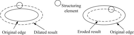
Fig. 2Dilation and erosion of image: a) original image; b) dilation of a); c) erosion of a)

a)

b)

c)
In general, as the fundamental algorithms of MM, the processed results of dilation and erosion cannot be recovered. Namely, the original image cannot be obtained through dilation and then erosion or the contrary order. However, the two orders are another two important algorithms of MM, opening and closing, and they can be denoted as and :
Fig. 3The processed results of opening and closing
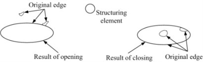
Fig. 4Opening and closing of image: a) original image; b) opening of a); c) closing of a)

a)

b)

c)
Similarly, the processed results of opening and closing can be illustrated by Fig. 3. It can be seen from the figure that opening and closing have the function of smooth edge and fill leak, respectively. The two results can be illustrated more visually by Fig. 4.
2.2. The application of MMFs in mechanical fault diagnosis
Section 2.1 introduced the fundamental theory of MM and its application on image processing. In recent years, mathematical morphological filters (MMFs) which mainly constituted by dilation, erosion, opening and closing were applied in fault diagnosis field.
Assume that , and , are input signal and structuring element, respectively. Then four basic MMFs can be defined as:
where , , and mean dilation, erosion, opening and closing filter, respectively.
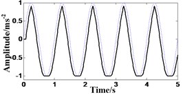
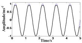
The functions of the four basic MMFs are different though all of them can extract the faults characteristic frequency from vibration signal. Fig. 5 shows the differences of them. The analyzed signal is a standard sine signal and the sampling frequency is 100 Hz. As the figure shows, dilation filter can control the plus pulse and sharp the minus pulse but erosion filter is just the reverse. Opening filter can eliminate the plus pulse and keep the minus pulse but closing filter is the reverse.
Fig. 5Results of the four basic MMFs (- - - Original signal, — Results of the four basic MMFs)
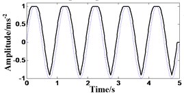
a) Result of dilation filter
b) Result of erosion filter
c) Result of opening filter
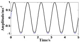
d) Result of closing filter
As described above, each of the four MMFs could only extract one of the plus or minus pulse information from vibration signal. However, the general condition in practical is that plus and minus pulse are needed at the same time. Therefore, the combination of the two of them were proposed and named morphological gradient filters (MGFs). Two MGFs, morphological dilation-erosion gradient filter (MGFDE) and morphological closing-opening gradient filter (MGFCO), can be defined as follows:
MGFs can take into account both plus and minus pulse. In addition, they can also extract the wanted faults characteristic frequency and weaken the interference of other signal.
2.3. The proposed method based on EMD and AMMGF
In general, different results will be obtained when selecting different structuring elements. Small-scale structuring element can keep the specific characteristic of pulse signal while big-scale structuring element can weaken the interference of noise signal. Therefore, selecting a suitable structuring element is very important. This paper proposed the adaptive multi-scale morphological gradient filter (AMMGF).
Assume that is dispersed signal, is morphological transform, and then the AMMGF can be summarized as the set of . Where was defined as:
Similarily, assume that and are input signal and structuring element, respectively. Then the multi-scale morphological dilation and erosion filters can be defined as:
where is the structuring element which its scale is . It can be obtained through dilate by times, as follows:
At the same time, the algorithems also can be applied to the followed equations:
The multi-scale morphological opening, closing and two gradient filters can be obtained according to the above equations, as follows:
Many multi-scale morphological transformed results would be getted through the method described above. Then how to merge them together is another problem. This paper utilized weighting and average method.
Assume that the set of all scales of structuring elements is , the obatined filtered results are , , . Then the results can be merged using weighting and averaging method, as follows:
where , .
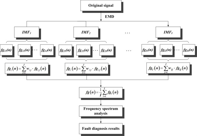
Theoretically, the above AMMGF can both keep the specific characteristic of pulse signal and weaken the interference of noise signal. However, due to the specialty of planetary gearbox, the practical application result was unsatisfactory. Therefore, this paper proposed the fault diagnosis method for planetary gearbox based on EMD and AMMGF. The framework of the method proposed in this paper can be seen in Fig. 6. And the specific procedures can be described as follows.
1. Decomposing the original signal using EMD and getting IMFs.
2. Processing every IMF using AMMGF and obtaining a lot of processed results with different scales of structuring elements.
3. Merging the processed result of each IMF using weighting and averaging method, getting AMMGF results of IMFs.
4. Calculating the mean value of the results as the final signal.
5. Analyzing the frequency spectrum of the final signal and assessing the health condition of planetary gearbox.
Fig. 6Framework of the method proposed in this paper
3. Example 1: experimental data analysis
3.1. Data specifications
The data this example used to validate the effectiveness of the method proposed in this paper was acquired from a seeded failure experiment of planetary gearbox. The experimental system consists of a tested planetary gearbox, a drive motor, a speed and torque sensor and a magnetic powder brake. And between the two of them is connected by coupling, as shown in Fig. 7.
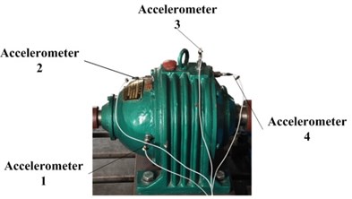
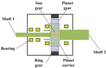
Four accelerometers were mounted on the tested planetary gearbox, wherein the first one and the second one are mounted on the input side of the gearbox, the third one is on the top of the casing and the fourth is fixed on the output side. The specific location of every accelerometer is as depicted in Fig. 8(a). Fig. 8(b) is the structure of the planetary gearbox. And the configuration parameters of the planetary gearbox can be seen in Table 1.
Table 1Planetary gearbox configuration parameters
Gear | Sun gear | Planet gear (number) | Ring gear |
Number of teeth | 13 | 64 (3) | 146 |
Fig. 7Planetary gearbox experimental system
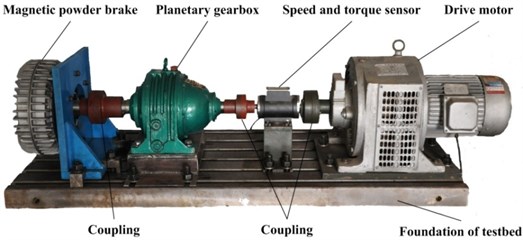
Fig. 8a) Mounted location of each accelerometer; b) structure of the tested planetary gearbox
a)
b)
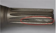
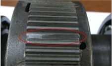
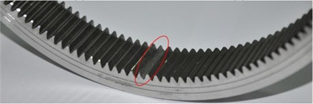
The wear failure is seeded on one tooth of sun gear, planet gear and ring gear, respectively. The specific failures are as Fig. 9 shows. The sampling frequency of this experimental system is 20 kHz, and 240000 points of data are recorded for every signal. The input shaft, shaft 1, was driven by the motor at three kinds of rotary speed, 400, 800 and 1200 rpm. To each speed, four different kinds of loads are implemented. They are 0, 0.4, 0.8 and 1.2 Nm, respectively.
Fig. 9Seeded wear failure of every gear: a) sun gear; b) planet gear; c) ring gear
a)
b)
c)
3.2. Results analysis
According to the configuration parameters of the planetary gearbox, the relevant fault characteristic frequencies can be obtained. The specific values of the frequencies can be seen in Table 2.
Firstly, the sun gear fault signal which acquired from the working condition of 1200 rpm and 1.2 Nm was analyzed to validate the effectiveness of the method proposed in this paper. The fault characteristic frequency of the sun gear in this condition is 55.093 Hz. The vibration signal acquired by Accelerometer 3 was utilized in this example.
Table 2Fault characteristic frequencies of every gear
Rotary speed (rpm) | Meshing frequency (Hz) | Fault frequency of sun gear (Hz) | Fault frequency of planet gear (Hz) | Fault frequency of ring gear (Hz) |
400 | 79.579 | 18.364 | 1.243 | 1.635 |
800 | 159.158 | 36.729 | 2.487 | 3.270 |
1200 | 238.738 | 55.093 | 3.730 | 4.906 |
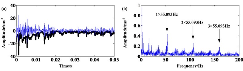
Fig. 10 shows the waveform in time domain and frequency spectrum of the sun gear fault signal. The 1 and 2 times of sun gear fault characteristic frequency can be seen in the figure, but the amplitudes of them are much lower compared to the disturbed signal’s. Therefore, the health condition of the sun gear cannot be assessed.
Fig. 10Sun gear fault signal: a) waveform in time domain; b) frequency spectrum
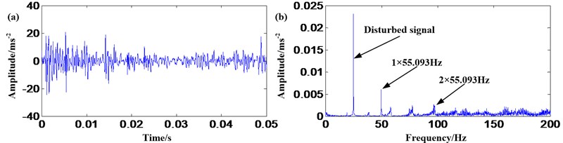
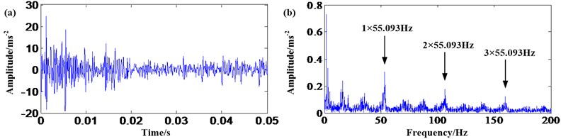
Fig. 11 shows the envelope analysis results of the sun gear fault signal. It can be seen from the figure that the 1, 2 and 3 times of sun gear fault characteristic frequency are very obvious. However, the noise interference is also very serious. The results are obtained based on the seeded wear failure experiment which the damage is a little severe. If the failure is slight or initial in the industrial machine, the result will be not so obvious. Therefore, it is needed to study a more effect method.
Fig. 11Envelope analysis of sun gear fault signal: a) waveform in time domain; b) frequency spectrum
Figs. 12-17 show the results of the six kinds of filters. Figs. 12-15 are the results of the four basic filters. They are dilation, erosion, opening and closing. Figs. 16-17 are the results of MGFDE and MGFCO. In the six figures, the bold and thin lines in (a) are the results of filters and the waveform in time domain of original signal, respectively.
It can be seen from Figs. 12-15 that the results of the four basic filters are similar. All of the four basic filters can extract 1, 2 and 3 times of the sun gear fault characteristic frequency. However, the amplitudes of these frequencies have not increased compared to the envelope analysis result. Even the amplitudes of some results have reduced, such as the results of opening and closing. In addition, the interference come from the low frequency noise is still very serious.
Fig. 12Sun gear fault signal: a) result of dilation; b) frequency spectrum
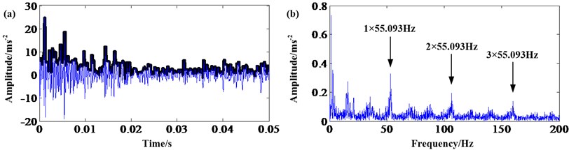
Fig. 13Sun gear fault signal: a) result of erosion; b) frequency spectrum
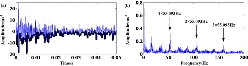
Fig. 14Sun gear fault signal: a) result of opening; b) frequency spectrum
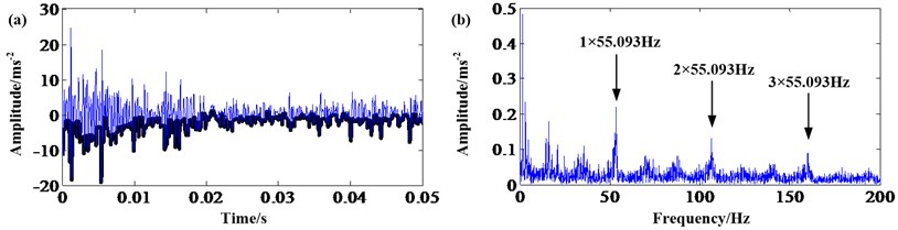
Fig. 15Sun gear fault signal: a) result of closing; b) frequency spectrum
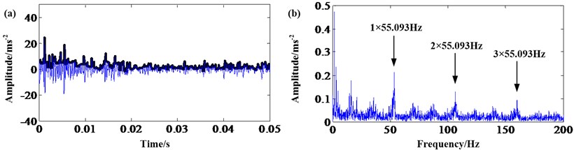
Fig. 16Sun gear fault signal: a) result of MGFDE; b) frequency spectrum
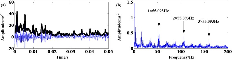
Fig. 16 and Fig. 17 are the results of MGFDE and MGFCO. Comparing to the results of the four basic filters, the amplitudes of the extracted sun gear fault characteristic frequency have increased obviously. This effect is significant to the frequency spectrum analysis of the signal acquired from the equipment with slight failure.
Fig. 17Sun gear fault signal: a) result of MGFCO; b) frequency spectrum
It also can be seen from the comparison of Fig. 16 and Fig. 17 that the effect of MGFDE is better than the effect of MGFCO due to the fault characteristic frequency amplitude extracted by MGFDE is higher than by MGFCO. In addition, another conclusion can be drawn from Eqs. (6)-(11) that MGFDE needs about half steps compared with MGFCO. Therefore, the after study is mainly implemented based on MGFDE.
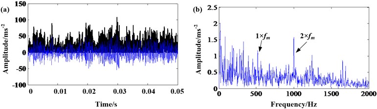
Fig. 18 shows the result of AMMGFDE. The 1, 2 and 3 times of the sun gear fault characteristic frequency are extracted obviously. And the amplitudes of them is much higher than the above six results. In addition, the effect of de-noising is also satisfactory.
Fig. 18Sun gear fault signal: a) result of AMMGFDE; b) frequency spectrum
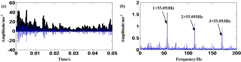
Fig. 19 shows the result of EMD and AMMGFDE which is the method proposed in this paper. It can be seen from the figure that the de-noising effect is also satisfactory. More important is that the amplitudes of the extracted sun gear fault characteristic frequencies are much higher than before. In addition, the fault characteristic frequencies of planet and ring gears are very low. So, the proposed method is more suited to planetary gearbox fault diagnosis.
Fig. 19Sun gear fault signal: a) result of EMD and AMMGFDE; b) frequency spectrum
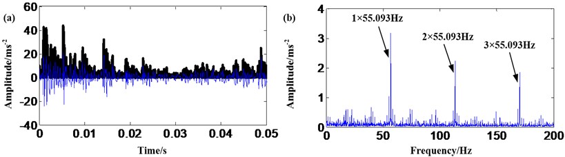
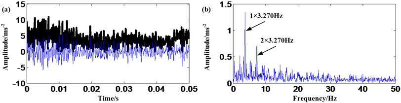
Fig. 20 and Fig. 21 are the results of EMD and AMMGFDE that applied to planet and ring gears, respectively. In order to achieve the goal of considering all working conditions, the data acquired from 400 rpm and 0.4 Nm condition is utilized when analyzing planet gear signal. And when analyzing ring gear signal, the data acquired from 800 rpm and 0.8 Nm condition is used. The fault characteristic frequencies of the planet gear and ring gear in the two conditions are 1.243 and 3.270 Hz, respectively.
It can be seen from Fig. 20 and Fig. 21 that the proposed method can extract the fault characteristic frequencies of the planet and ring gear obviously even though the frequencies are very low. In addition, the effect of de-noising of the proposed method is also satisfactory.
Above discussion demonstrates the offline fault diagnosis method for planetary gearbox proposed in this paper can extract fault characteristic frequencies more prominent compared to the four basic filters (dilation, erosion, opening and closing) and two MGFs (MGFDE and MGFCO). And the de-noising effect of the proposed method is also satisfactory. In addition, the performance of EMD and AMMGFDE is the best among all of the filters.
Fig. 20Planet gear fault signal: a) result of EMD and AMMGFDE; b) frequency spectrum
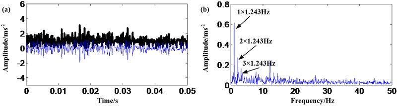
Fig. 21Ring gear fault signal: a) result of EMD and AMMGFDE; b) frequency spectrum
4. Example 2: industrial data analysis
4.1. Data specifications
In order to further validate the effectiveness of the offline fault diagnosis method for planetary gearbox proposed in this paper, industrial data acquired from a helicopter was analyzed.
Planetary gearbox is a main part of helicopter engine and this is the reason why select the data acquired from helicopter to analyze. Due to the reason of secrecy, the photo of the helicopter and the inside structure of planetary gearbox cannot be showed here. But the configuration parameters of the planetary gearbox can be seen in Table 3.
Table 3The configuration parameters of the planetary gearbox of a helicopter
Gear | Sun gear | Planet gear (number) | Ring gear |
Number of teeth | 94 | 36 (10) | 167 |
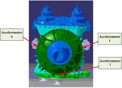
Eight accelerometers are installed on the engine of the helicopter and the first, sixth and seventh were installed on the casing of the planetary gearbox. The diagram of the specific locations can be seen in Fig. 22.
The rotary speed of the sun gear shaft was 574.74 rpm and it is constant due to the speciality of helicopter. Three kinds of torque are implemeted and they are 30 %, 40 % and 50 % of the rated torque of the helicopter. The data is acquired during the flight time 600 h to 800 h. It is found through open-gearbox examination that the planetary gearbox is healthy after testing. Continue experiment has not been implemented with considering the economy and safety.
Fig. 22The diagram of accelerometers installed on the casing of the planetary gearbox
4.2. Results analysis
Similarily, according to the configuration parameters of the helicopter planetary gearbox, the relevant fault characteristic frequencies can be obtained. The specific values of the frequencies can be seen in Table 4.
Table 4Fault characteristic frequencies of every gear of helicopter planetary gearbox
Rotary speed (rpm) | Meshing frequency (Hz) | Fault frequency of sun gear (Hz) | Fault frequency of planet gear (Hz) | Fault frequency of ring gear (Hz) |
574.74 | 576.15 | 61.29 | 16.00 | 34.50 |
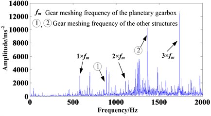
Firstly, the frequency spectrum of the acquired signal is analyzed. This paper utilizes the vibration signal acquired by Accelerometer 1. Fig. 23 shows the frequency spectrum analysis of the vibration signal. Only the 1, 2 and 3 times of the planetary gearbox gear meshing frequency appeared. This is a normal phenomenon and it also can demonstrate the planetary gearbox is healthy. In addition, it can be seen in Fig. 23, the frequency amplitudes of some other structures are very high. If the planetary gearbox is damaged, these frequencies will disturb the fault diagnosis of it. Therefore, an effective fault diagnosis method for helicopter planetary gearbox is very important.
Fig. 23Frequency spectrum analysis of the signal acquired from the helicopter planetary gearbox
Generally, due to the planetary gearbox is healthy, but the effectiveness of the proposed method also can be validated if the proposed method has good performance when analyzing the data acquired from different working conditions. Therefore, the signal acquired from the three kinds of torques is analyzed in this section and the results can be seen in Fig. 24, 25 and 26.
Fig. 24The signal of 30 % rated torque: a) results of EMD and AMMGFDE; b) frequency spectrum
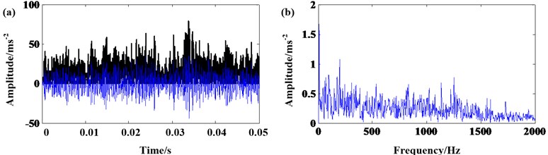
Fig. 25The signal of 40 % rated torque: a) results of EMD and AMMGFDE; b) frequency spectrum
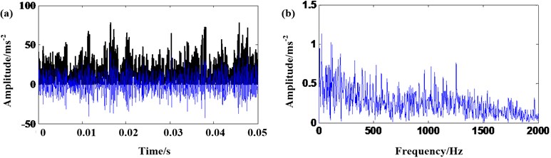
Fig. 26The signal of 50 % rated torque: a) results of EMD and AMMGFDE; b) frequency spectrum
It can be seen from the three results that there is not fault characteristic frequency of any structure of the helicopter engine in each frequency spectrum. Only 1 and 2 times of the planetary gearbox meshing frequency appear in the frequency spectrum of 50 % rated torque. So, it can be assessed that the planetary gearbox is healthy. In addition, disturbed frequencies can not be seen in each frequency spectrum compared with the original analysis in Fig. 23. Therefore, the effectiveness of the method proposed in this paper can be further validated.
5. Conclusions
An offline fault diagnosis method for planetary gearbox based on EMD and AMMGF was proposed in this paper. Firstly, the basic theory of MM was introduced thoroughly and the framework of the proposed method was given out. Then, experimental data and industrial data were utilized to validate the effectiveness of the method. And the combination of EMD and AMMGFDE was found very suitable to be used in the planetary gearbox fault diagnosis compared with other six filters (dilation, erosion, opening, closing, MGFDE and MGFCO). The results from the two kinds of data show that the proposed method has good performance on both extracting fault characteristic frequency and de-noising. Therefore, the method is very suitable for offline planetary gearbox fault diagnosis.
References
-
Lei Y. G., He Z. J., Lin J., et al. Research advances of fault diagnosis technique for planetary gearboxes. Journal of Mechanical Engineering, Vol. 47, Issue 19, 2011, p. 59-67, (in Chinese).
-
Feng Z. P., Zuo M. J. Vibration signal models for fault diagnosis of planetary gearboxes. Journal of Sound and Vibration, Vol. 331, 2012, p. 4919-4939.
-
Feng Z. P., Zuo M. J. Fault diagnosis of planetary gearboxes via torsional vibration signal analysis. Mechanical Systems and Signal Processing, Vol. 36, 2013, p. 401-421.
-
Liu Z. L., Qu J., Zuo M. J., Xu H. B. Fault level diagnosis for planetary gearboxes using hybrid kernel feature selection and kernel Fisher discriminant analysis. The International Journal of Advanced Manufacturing Technology, Vol. 67, 2013, p. 1217-1230.
-
Jardine A. K. S., Lin D. M., Banjevic D. A review on machinery diagnostics and prognostics implementing condition-based maintenance. Mechanical Systems and Signal Processing, Vol. 20, 2006, p. 1483-1510.
-
Samuel P. D., Pines D. J. A review of vibration-based techniques for helicopter transmission diagnostics. Journal of Sound and Vibration, Vol. 282, 2005, p. 475-508.
-
Lebold M., McClintic K., Campbell R., et al. Review of vibration analysis methods for gearbox diagnostics and prognostics. Proceeding of the 54th Meeting of the Society for Machinery Failure Prevention Technology, 2000, p. 623-634.
-
Baccarini L. M. R., Silva V. V. R., Meneze B. R. D., et al. SVM practical industrial application for mechanical faults diagnostic. Expert Systems with Applications, Vol. 38, 2011, p. 6980-6984.
-
Tang X. L., Zhuang L., Cai J., et al. Multi-fault classification based on support vector machine trained by chaos particle swarm optimization. Knowledge-Based Systems, Vol. 23, 2010, p. 486-490.
-
Yen G. G., Leong W. F. Fault classification on vibration data with wavelet based feature selection scheme. Instrumentation, Systems, and Automation Society, Vol. 45, 2006, p. 141-151.
-
Fan X. F., Zuo M. J. Gearbox fault detection using Hilbert and wavelet packet transform. Mechanical Systems and Signal Processing, Vol. 20, 2006, p. 966-982.
-
Boutros T., Liang M. Detection and diagnosis of bearing and cutting tool faults using hidden Markov models. Mechanical Systems and Signal Processing, Vol. 25, 2011, p. 2012-2124.
-
Kang J. S., Zhang X. H. Application of hidden Markov models in machine fault diagnosis. Information-An International Interdispilinary Journal, Vol. 15, 2012, p. 5829-5838.
-
Hassiotis S. Identification of damage using natural frequencies and Markov parameters. Computers and Structures, Vol. 74, 2000, p. 365-373.
-
Huang N. E., Shen Z., Long S. R., et al. The empirical mode decomposition and the hilbert spectrum for nonlinear and nonstationary time series analysis. Proceeding of the Royal Society of London, Series A, Vol. 454, 1998, p. 903-995.
-
Li H., Zhang Y. P., Zheng H. Q. Wear detection in gear system using Hilbert-Huang transform. Journal of Mechanical Science and Technology, Vol. 20, Issue 11, 2006, p. 1781-1789.
-
Ricci R., Pennacchi P. Diagnostics of gear faults based on EMD and automatic selection of intrinsic mode functions. Mechanical Systems and Signal Processing, Vol. 25, Issue 3, 2011, p. 821-838.
-
Loutridis S. J. Damage detection in gear systems using empirical mode decomposition. Engineering Structures, Vol. 26, Issue 12, 2004, p. 1833-1841.
-
Blunt D. M., Keller J. A. Detection of a fatigue crack in a UH-60A planet gear carrier using vibration analysis. Mechanical Systems and Signal Processing, Vol. 20, 2006, p. 2095-2111.
-
Dai Q. Y., Yu Y. L. The advances of mathematical morphology in image processing. Control Theory and Applications, Vol. 18, 2001, p. 478-482, (in Chinese).
-
Li B., Zhang P. L., Wang Z. J., et al. Gear fault detection using multi-scale morphological filters. Measurement, Vol. 44, 2011, p. 2078-2089.
-
Li B., Zhang P. L., Mi S. S., et al. An adaptive morphological gradient lifting wavelet for detecting bearing defects. Mechanical Systems and Signal Processing, Vol. 29, 2012, p. 415-427.
-
Morenilla A. J., Carmona R. M., Romero J. L. Mathematical morphology for design and manufacturing. Mathematical and Computer Modeling, Vol. 54, 2011, p. 1753-1759.
About this article

