Abstract
Pseudo-fault signal assisted empirical mode decomposition (PFS-EMD) is put forward for fault detection and isolation, which is built upon EMD, envelope analysis and pseudo-fault signal. And this method has been proved that it is usable in fault diagnosis of simple gear pair. However, this method is still need further study that whether it can be used for fault diagnosis of complex gearbox. Moreover, planetary gearbox fault diagnosis is much more complicated than fixed-axis gearbox. This paper makes a further study of PFS-EMD and focuses on its application. Combining with the seeded failure experimental data of planetary gearbox, this paper show that PFS-EMD can enhance fault information and weaken other useless information in complex gearbox fault diagnosis.
1. Introduction
Vibration is an important monitoring method of rotating machinery, and it is great significance to accurately extract the fault information from vibration signals [1]. Signal processing methods are usually used to analyze and extract the fault characteristic frequency, and they are becoming a common technology in rotating machinery condition monitoring process. Wavelet transform (WT) [2] and empirical mode decomposition (EMD) [3] are two widely used methods of signal processing. WT method needs to choose different wavelet basis functions to determine the wavelet coefficients in order to reconstruct the signal [2]. Compared with WT, the EMD method does not need basis function in the process of characteristic frequency extraction from vibration signal, which is a kind of adaptive nonlinear and non-stationary data analysis method [4]. The EMD method decomposes nonlinear and non-stationary signal into a series of intrinsic mode function (IMF). And the IMF is a kind of basically orthogonal, adaptive and complete expression, which is confirmed by original signal rather than preset basic functions [5]. EMD is widely used in processing non-linear and non-stationary signal [6].
Dheeraj proposed a idea of injecting pseudo-fault signal to the signal envelope in fault detection and isolation of rotating machinery [7]. The method is built upon EMD, envelope analysis and pseudo-fault signal. He proved this method is usable in fault diagnosis of simple gear pair. However, it is still need further study that whether this method can be used for fault diagnosis of complex gearbox.
As the advantages of strong load-bearing capacity, large transmission ratio, etc., planetary gearboxes are widely used in modern industry. Planetary gearboxes significantly differ from fixed-axis gearboxes because of their unique structure [8]. As a result, planetary gearbox fault diagnosis are much more complicated than fixed-axis gearbox.
This paper makes a further study of PFS-EMD and focuses on its application. Combining with the seeded failure experimental data of planetary gearbox, this paper verifies the effectiveness of PFS-EMD in complex gearbox fault diagnosis.
2. Pseudo-fault signal theory
In PFS-EMD method, the frequency of masking signal is predetermined by the known system fault frequency, thus it is considered as pseudo-fault signal. In order to clearly describe the concept of pattern recognition, the fault signal is assumed as two closer frequency band signal components. In this article, two signal components are expressed by the sine function:
where represents the higher frequency components, on behalf of the low frequency components.
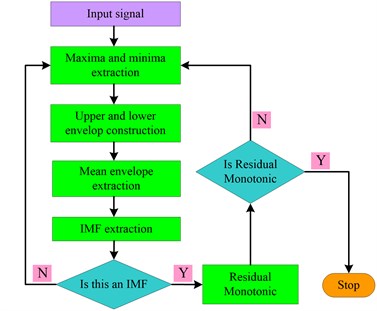
When performing EMD (The procedure for performing the EMD method is shown in Fig. 1), the first step in the sifting process is to find the extreme value point of signal and create upper and lower envelope. Moreover, the extreme value distribution depends on the signal component. Pseudo-fault signal is used to change the distribution of extreme value. As a result, the average envelope got by EMD should contain only low frequency components:
Fig. 1Procedure for performing the EMD
2.1. The positive fault IMF
The positive synthesized signal is obtained from envelope signal (containing fault information) and pseudo-fault signal . EMD Processing and achieving the positive IMF :
In pseudo-fault signal , in order to make the mean extrema rate of is equal to (namely ), should be big enough. Let as the set of local maxima of , and can be written as:
The ideal curve, which connect all of maxima value (namely upper envelope), can be expressed as:
where is the sampling interval of extrema.
Because of sampling for the extreme value, the higher frequency components of signals will loss information as aliasing, the lower frequency components will be reconstructed by the means of minimum information loss. As the assumption , the pseudo-fault signal will produce a constant DC term. Therefore, the upper envelope can be expressed as:
where is a constant, is the edition of higher frequency components after aliasing. Similarly, the lower envelope can be written as:
The average envelope can be obtained as:
In the Eq. (9), it is the lower frequency component in the first term of right hand expression, and it is average envelope for the higher frequency components after aliasing. Averaging operation further weaken the influence of higher frequency components by aliasing envelope [9]. As a result, the positive IMF can be calculated as:
where is the error signal.
2.2. The negative fault IMF
The negative fault IMF is extracted through the similar series of operation on negative synthesized signal :
Ignoring the error terms in Eqs. (10) and (11), the output signal after PFS-EMD operation can be achieved as:
Fig. 2Procedure for performing the PFS-EMD
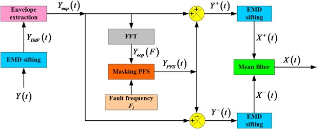
It can be found from Eq. (12) that the pseudo-fault signal can help in separating signals of closer frequency bands, which is out of reach for standard EMD method. The signal dealing process of PFS-EMD method are shown in Fig. 2.
3. PFS-EMD method
The proposed PFS-EMD method is used to extract the fault characteristics of rotating machinery, the specific steps are as follows:
(a) Calculating the failure frequency ( 1, 2,..., ) corresponding to various failure modes.
(b) Identifying the th IMF that there is a peak close to in frequency spectrum:
where is Fourier transform of the th IMF , is a very small value and it is taken as 0.05 in this paper.
(c) Structuring a pseudo-fault signal, which with constant amplitude and constant frequency:
On the advice of previous research [7], this paper let 1.1 and 1.6.
(d) Performing standard EMD to get the first IMF from and get the second IMF from .
(e) Obtaining fault indicator signal:
(f) Extracting fault information from fault indicator signal .
4. Planetary gearbox fault diagnosis
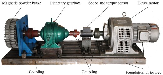
A case study is carried out for planetary gearbox fault diagnosis based on PFS-EMD. In order to validate the effectiveness of the proposed method, a seeded failure experiment of planetary gearbox to obtain failure data. The experiment rig consists of a test planetary gearbox, a drive motor, a speed and torque sensor, and a magnetic powder brake, as shown in Fig. 3. There are four accelerometers fitted onto the casing of gearbox to record vibration data, as shown in Fig. 4. Schematic map of planetary gearbox structure and related configuration parameters are shown in Fig. 5. The failure is seeded on sun gear, planet gear and ring gear, respectively, as shown in Fig. 6. Fault characteristic frequencies of every gear is shown in Table 1.
Fig. 3Planetary gearbox experiment rig
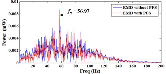
Frequency spectrum of sun gear fault is shown as Fig. 7, blue frequency spectrum is decomposed by standard EMD without pseudo-fault signal, red frequency spectrum is decomposed by PFS-EMD. It can be found that the amplitude of red frequency spectrum is lower than blue frequency spectrum in whole frequency bands. But in fault frequency of sun gear ( 56.97), the amplitude of red signal is significantly higher than blue signal. This phenomenon shows that fault information has been enhanced, while other useless information has been weakened.
Table 1Fault characteristic frequencies of every gear (Hz)
Fault frequency of sun gear | Fault frequency of planet gear | Fault frequency of ring gear |
55.093 | 3.730 | 4.906 |
Fig. 4Mounted location of accelerometers
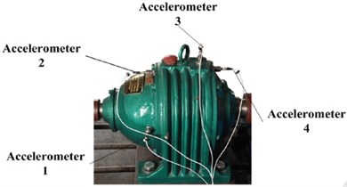
Fig. 5Schematic map of planetary gearbox structure
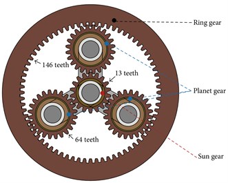
Fig. 6Implanted wear fault: a) sun gear, b) planet gear, and c) ring gear
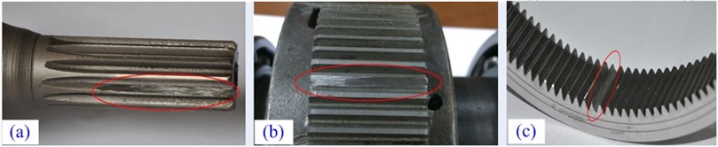
Fig. 7Frequency spectrum of sun gear fault
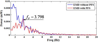
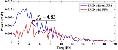
Frequency spectrums of planet gear fault and ring gear fault are shown as Fig. 8. It cannot found the fault characteristic frequency information in the frequency spectrums, which are decomposed by standard EMD without pseudo-fault signal. While in the frequency spectrums which are decomposed by PFS-EMD, there are two significant peaks in fault characteristic frequencies of planet gear fault and ring gear fault, the fault features are obvious.
In order to further verify the effect of the proposed method, signal to noise ratios (SNR) are analyzed. The SNR can be caudated as follow:
stand for spectrum amplitude of frequency , is average spectrum amplitude. All SNR of every gear fault is shown in Table 2. It can be found that the SNR of PFS-EMD is much greater than EMD without PFS. It shows that PFS-EMD can enhance useful information in fault diagnosis.
Fig. 8Frequency spectrum: a) planet gear fault, b) ring gear fault
a)
b)
Table 2SNR of every gear fault
SNR of sun gear fault | SNR of planet gear fault | SNR of ring gear fault | |
EMD without PFS | 10.2976 | 3.4278 | 2.3679 |
EMD with PFS | 15.5547 | 8.4135 | 8.0443 |
5. Conclusions
This paper is meant to further investigate the theory and application in complex gearbox of PFS-EMD. Pseudo-fault signal theory is future studied and the specific steps of PFS-EMD are given. A case study of planetary gearbox fault diagnosis based on PFS-EMD is analysis, which include sun gear fault, planet gear fault and ring gear fault. The frequency spectrum and SNR show that PFS-EMD can enhance fault information and weaken other useless information in complex gearbox fault diagnosis.
References
-
Li M., Xu J., Yang J., Yang D. Multiple manifolds analysis and its application to fault diagnosis. Mechanical Systems and Signal Processing, Vol. 23, 2009, p. 2500-2509.
-
Gilles J. Empirical wavelet transform. IEEE Transactions on Signal Processing, Vol. 61, 2013, p. 3999-4010.
-
Lei Y. G., Lin J., He Z. J., Zuo M. J. A review on empirical mode decomposition in fault diagnosis of rotating machinery. Mechanical Systems and Signal Processing, Vol. 35, 2013, p. 108-126.
-
Bi N., Sun Q. Y., Huang D. R., Yang Z. H., Huang J. W. Robust image watermarking based on multiband wavelets and empirical mode decomposition. IEEE Transactions on Image Processing, Vol. 16, 2007, p. 1956-1966.
-
Lv Y., Yuan R., Song G. B. Multivariate empirical mode decomposition and its application to fault diagnosis of rolling bearing. Mechanical Systems and Signal Processing, Vol. 81, 2016, p. 219-234.
-
Klionski D. M., Oreshko N. I., Geppener V. V. Applications of empirical mode decomposition for processing nonstationary signal. Pattern Recognition and Image Analysis, Vol. 18, 2008, p. 390-399.
-
Singh D. S., Zhao Q. Pseudo-fault signal assisted EMD for fault detection and isolation in rotating machines. Mechanical Systems and Signal Processing, Vol. 81, 2016, p. 202-218.
-
Lei Y. G., Han D., Lin J., et al. Planetary gearbox fault diagnosis using an adaptive stochastic resonance method. Mechanical Systems and Signal Processing, Vol. 38, 2013, p. 113-124.
-
Yang Y., Miao C., Deng J. Research on the mechanism of masking signals technique to improve empirical mode decomposition. Journal of Information and Computational Science, Vol. 9, 2012, p. 3509-3516.
About this article

