Abstract
The hanging sleeper under train dynamic loads result in discrete contact and breakage of ballast particles, and accelerate ballast bed degradation and deformation. A sleeper-ballast dynamic interaction model was established to analyze the effects of hanging sleeper due to the sleeper dynamic response. In this research, the Discrete Element Method (DEM) was applied to simulate the hanging sleeper dynamic characteristics of ballast bed, where the irregular ballast particle was constructed by clusters, and the ballast particle breakage under dynamic cyclic loads was investigated. The nonlinear contact force model of Mohr-Coulomb was adopted to model the cluster particles. The ballast breakage function and dynamic simulation were employed, with local damping method. Numerical results indicated that hanging sleeper altered the contact force distribution state, the hanging sleepers would incur centralized contact force under sleepers, more ballast particles breakage, and ballast lateral resistance reduction varied with hanging sleeper situations. Some ballasted track improvements should be considered in practice, such as increase thickness of ballast bed, improve ballast compaction, and reduce vibration tamping produced voids.
1. Introduction
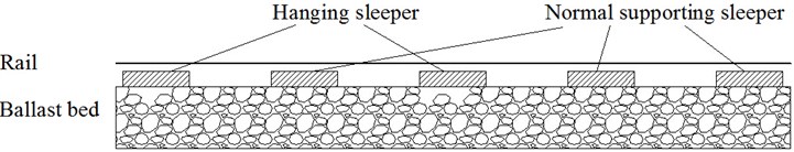
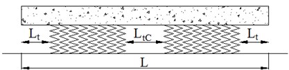
Railway sleepers and ballast are the main structural elements of railway track. The ballast-sleeper interactions include pressure distribution and load transfer to ballast, railway sleepers are aimed to maintain track gauge, guarantee lateral stability of the track and contribute to better geometrical conditions of the track. The structure of ballast bed is to contribute two basic functions vertically and laterally. Vertically is to provide good elastic and evenly support beam, while laterally is to resist lateral loading from train and prevent rail buckling, the interaction of sleeper-ballast is of great importance to the above issues, for example, it is very difficult to predict correct distribution of contact stress on a sleeper [1-2], especially the hanging sleepers microscopic effects and mechanism illustrated by Fig. 1.
Fig. 1Hanging sleeper mechanism
Augustin concluded that hanging sleepers occupy about 50 % of total sleepers, and resulted in great dynamic force and ballast bed settlement, as well as increase of degradation and maintenance cost [1]. Lots of researchers conducted experiments and simulations to investigate the responses of hanging sleepers [1-6], most of the simulations were with the tool of FEM, for example, Yang employed dynamic system using the FEM package ABAQUS to model the railway track as well as a train comprising three typical freight wagons for the hanging sleeper effects, concluded that hanging sleeper may lead to significantly increased stresses below the neighboring sleeper in the sub-ballast layer [6]. Shi developed dynamic FEM using linear elastic material properties while including wheel-rail friction [7]. However, hanging sleeper dynamic interactions with granular ballast could result in discrete contact and breakage of the ballast particles, reduce the fatigue life of the sleeper, and accelerate ballast bed progressive degradation and differential settlement. Sadeghi took the rail bending moment as an index to investigate the effects of sleeper hanging on concrete sleeper and timber sleeper [8]. Li analyzed the effects of hanging sleeper on load distribution [9]. The above for hanging sleeper interaction with ballast bed is not well micro-analyzed, the micro-level reactions between the discrete granular ballast and solid rigid hanging concrete sleeper, under the dynamic load, such as the distribution of the dynamic contact force, ballast particle re-displacements etc. in particular, the different type of hanging sleeper dynamic interactions situation evaluation and assessment.
The present study investigated the hanging sleeper interaction with ballast in microscopic perspective, and hanging sleeper responses under dynamic load were studied. The Discrete Element Method (DEM) was used to analyze the hanging sleeper interactions, which plays a role in protecting the track from geometry deterioration, and is of great importance for the Continuous Welded Rail (CWR) stability. The advantage of using DEM-based models is that assemblies of discrete ballast particles are able to capture the complicated behavior and interaction of actual materials with relatively simple assumptions and a small number of parameters at the micro-scale level [10-12], as well as the non-linear dynamic calculation [13-14]. In this paper, a dynamic DEM system of ballast-sleeper interaction was set up, and the dynamic granular material responses were micro-analyzed.
2. Hanging sleeper ballast interaction
2.1. Irregular ballast cluster
DEM was first proposed by Cundall. Compared with FEM, it overcomes the disadvantages of continuum mechanics. PFC3D is commercial software based on granular mechanics and the theory of DEM [11-12]. There are three methods to simulate ballast in PFC3D, including sphere, clump and cluster. Sphere is the basic element in PFC3D, and user can use it to model granular directly. Clump and cluster are combinations of spheres, which need the user to exploit with FISH language inserted in PFC3D. Clump and cluster own obvious advantages than simple sphere, as they can represent the interlocking behavior of real ballast and simulate the multi-contact property. However, they also have some disadvantages. Firstly, it usually takes more time to finish calculation, and exists overlapping in a clump. The problem of eccentricity has not solved well until now [12]. When generating clusters, there is no overlap during the process, and the problem of eccentricity do not exist for a cluster. What's more, as the spheres in a cluster are bonded together, when external force exceeds bond strength, the bonds can break. So, the cluster can be used to investigate broken characteristics of the ballast, such as position and number of broken bond during dynamic loads. Considering the factors mentioned above, the cluster was used to simulate ballast in this paper.
Based on former research results [15-16], clusters were generated in the following procedure. The first step was to create a regular tetrahedron, and using the four vertex of the regular tetrahedron as the centre of sphere to generate anther four tangent balls. Then an arbitrary face of the regular tetrahedron was used to produce another regular tetrahedron. The new vertex can be used to produce another ball, and the generation process can be repeated to create an irregular cluster. Based on this generation procedure, some created clusters are shown in Fig. 2.
When generating clusters, it is necessary to consider the conclusion from Lu [17], which points out that a cluster must contains more than 7 spheres to reveal interlocking behavior of real ballast. However, if a cluster contains too many spheres, the total calculation time for dynamic response is too long to finish. Note the two reasons above, the number of spheres of a cluster in this paper is more than 7 and less than 50.
Spheres in a cluster are bonded together, and PFC3D provides two bonding models: a contact-bond model and a parallel-bond model [18]. There is no relative displacement between spheres when the bond existences. Some researchers applied contact bond to simulate contact property between ballast particles, to investigate ballast particle breakage or wearing, based on existing research, contact bond was applied in this paper [18].
Fig. 2Models of cluster
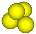
a) 4 balls
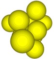
b) 10 balls

c) 20 balls
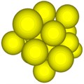
d) 25 balls
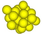
e) 30 balls
2.2. Sleeper-ballast model
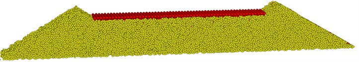
Ballast particles simulated by crushable clusters were used to establish DEM model of Chinese high-speed railway ballast bed. To start with, it is necessary to understand that Chinese Railway Ministry specifies the gradation used in high-speed railway, which is called special gradation. Based on the Code for Design of Chinese High Speed Railway, the special gradation of clusters was generated in the DEM model. In order to model the random distribution of ballast, all these ballast particles were dropped from a high place. After all ballast particles reached the bottom ground, a temporary wall was used to compact ballast bed, which was like the compaction process in engineering practice. Then ballast particles laid in the position of the sleeper were deleted, and then a sleeper was created at the designed place. The sleeper was simulated by spheres with regular arrangements. The sleeper was treated as a clump in this paper. The whole model establishment procedure can be referred to Lu et al [17, 19-20].
The cross-section of ballast bed model in this paper was according to the Code for Design of Chinese High-speed Railway. To be specific, the top width of ballast bed is 3.6 m, the thickness of ballast bed is 0.35 m, the gradient of ballast bed slope is 1:1.75 and shoulder height is 0.15 m. The different shape and size of ballast particles were produced in ballast bed randomly. The dimension of sleeper modelling in this paper is concrete type III that is used widely in Chinese high-speed ballasted track. The boundary conditions were modeled by walls. The DEM model of ballast bed is shown in Fig. 3.
Fig. 3Ballast-sleeper 3-D model
The spheres and walls were treated as rigid body in PFC3D. The interaction between spheres is based on Mohr-Coulomb code. The values of parameters in the model were determined by granular mechanics and existing research [16-17, 19-20]. The values of parameters are shown in Table 1.
For damping, when a dynamic simulation is required, the local damping coefficient should be set to a low value appropriate to energy dissipation of dynamic waves [18-19]. It should be noted, for the dynamic induced response, it is a dynamic simulation, with damping value set 0.157. The ratio of average unbalanced force to average contact force should be smaller than 0.01 before loading.
Table 1Parameters for ballast bed model
Ballast particle normal contact stiffness / (N/m) | 1×10⁸ |
Ballast particle shear contact stiffness / (N/m) | 1×10⁸ |
Wall normal contact stiffness / (N/m) | 1×10⁹ |
Wall shear contact stiffness / (N/m) | 1×10⁹ |
Sleeper particle normal contact stiffness / (N/m) | 5×10⁷ |
Sleeper particle shear contact stiffness / (N/m) | 5×10⁷ |
Ballast particle normal bond strength / (N) | 3000 |
Ballast particle shear bond strength / (N) | 3000 |
Ballast density / (kg/m3) | 2600 |
Sleeper density / (kg/m3) | 2800 |
Particle friction coefficient | 0.5 |
Wall friction coefficient | 0.5 |
2.3. Dynamic loads
Dynamic sinusoidal load was also applied on sleeper in the model, and the load formula is shown as follows:
where is the quarter peak value of pressure on sleeper, and it was 70 kN. When the train runs on track structure, train load was passed to the rail. The rail and sleeper is connected with fasters. There are four fasters on a sleeper to transit train load. is the pressure value of each faster. The load was applied on the position of fasters in the model. is the frequency of load and it was 20 Hz, which can represent the high-frequency of high-speed railway load. is the load time.
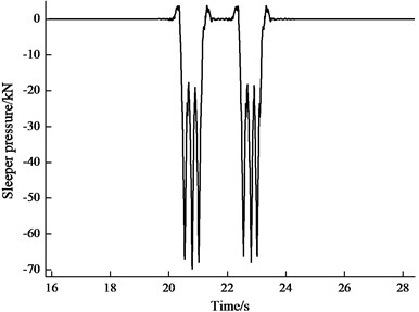
It is significant and meaningful to certificate the accuracy of DEM model. The authors had done field test in Beijing-Shanghai High-speed Railway ballasted track. In order to simulate sleeper pressure more accurately, sleeper pressure spectrum was compiled in FISH programming language, which was obtained in the following procedure. First, FEM simulation software ABAQUS was used to calculate the dynamic response of track structure. In order to keep the consistency of the model and reality, the simulation parameters of the train, track structure and subgrade were set according to the design parameters, i.e., the dimension and weigh of train, dimension and stiffness of track structure, etc. Then sleeper pressure was extracted during the train passed on track. The sleeper pressure is shown in Fig. 4. In PFC3D, the data of sleeper pressure was obtained in ABAQUS to acts on the sleeper in DEM model for each time step. Then the ballast vibration velocity can be got in PFC3D using some measured ballast particle. The vibration acceleration is the derivative of vibration velocity through mathematic process.
Fig. 4Sleeper dynamic load
The field tests and simulation results of ballast acceleration were compared to verify the accuracy of DEM model. In field test, ballast acceleration was measured through advance test facility. Fig. 5(a) shows field test result of ballast particle acceleration when the train passed at the speed of 30 kilometer per hour. Fig. 5(b) shows simulation result of ballast particle acceleration. It is obvious that the simulation results are in good agreement with field test results.
Fig. 5Test and simulation results for ballast acceleration
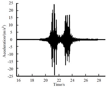
a) Test result
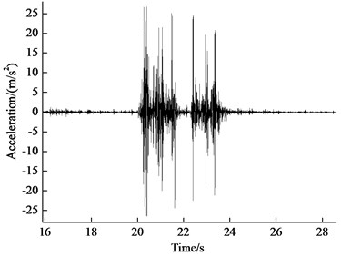
b) Simulation result
2.4. Hanging sleeper
In Finite Element Method (FEM), when investigating hanging sleeper the supporting stiffness and damp was set to zero [5-7], which means that the whole sleeper was hanging on the ballast bed. The existing FEM can be used to investigate the effect of hanging sleeper in a view macroscopically. However, this simulation method cannot represent the real situation of sleeper hanging. In fact, when the supporting of sleeper is in bad condition, only a partial area of sleeper lacks support from ballast particles, not the whole bottom surface. Considering the shortage of FEM, then DEM was used to simulate sleeper hanging in this paper. During the simulations, there was only partial of sleeper lacks supporting, and ballast particles in the area were deleted. In order to analyze the effects of different supporting conditions of sleeper on ballast mechanics [21], four cases were set in this paper, which is shown in Fig. 6. Fig. 6(a) represents the normal supporting condition, Fig. 6(b) represents both ends of sleeper hanging, Fig. 6(c) represents middle of sleeper hanging, and Fig. 6(d) represents both ends and middle of sleeper hanging. In these figures, the length of is 2.6 meter, and is 0.4 meter, is 0.8 meter, is 0.2 meter, and is 0.4 meter.
Fig. 6Different situations of supported sleeper
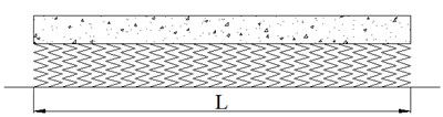
a) Case 1: normal supporting
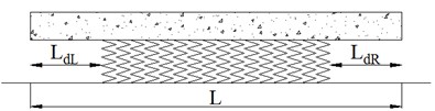
b) Case 2: both ends of sleeper hanging
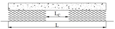
c) Case 3: middle of sleeper hanging
d) Case 4: both ends and middle of sleeper hanging
3. Results and discussion
Existing research illustrates that dynamic response of ballast bed increased significantly when the train passes the hanging sleeper areas [1-6]. Ballast particle dynamic mechanics was investigated in a micro-perspective in this paper. Ballast dynamic properties, e.g. particle contact force, sleeper settlement, ballast particle breakage and lateral ballast resistance variation were investigated.
3.1. Ballast contact force
The analytical model of contact force between particles can be explained through Fig. 7, which includes ball A, ball B and the contact plate. In DEM theory, the contact force can be divided into normal and shear components in terms of the contact plane. Normal contact forces act normal to the contact plane, while shear contact forces act in the contact plane [18].
Fig. 7Contact force between particles
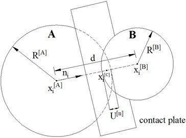
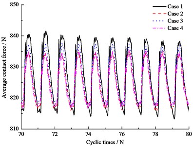
Sleeper bears dynamic impact load from wheel/rail interaction force, and distributes the load to ballast bed. However, when sleeper is hanging above the ballast bed, the normal contact force transition road is obstruent. It is easy to understand that some areas of ballast bed will appear overlarge contact force when hanging sleeper exists; ballast particles are much easily to break and wear as there is stress concentration under the situation. PFC3D can count the contact force for all particles and then calculate the average contact force, which can be used to analyze load distribution between particles. Fig. 8 shows the results of average contact force between ballast particles during cyclic loads. It is clear that simulation results of Case 1 is different from the others, the simulation Case 1 represents the normal supporting. When sleeper hanging occurs, it could reduce the maximum value of average contact force, while it would increase the minimum value of average contact force. It seems that hanging sleeper lead to the contact force between ballast particles become more concentrated. The ballast contact force varied with hanging sleeper type and position.
Fig. 8Average contact force between ballast particles
3.2. Sleeper settlement
Hanging sleeper will affect contact property between ballast bed and sleeper. As a smaller number of ballast particles bear the dynamic loads from sleeper, these ballast particles are much easier to migrate and flow, and sleeper settlement is expected to be larger than normal condition. There are two reasons contributing to sleeper settlement, including ballast movement and ballast breakage. The two factors were all taken into account in this paper.
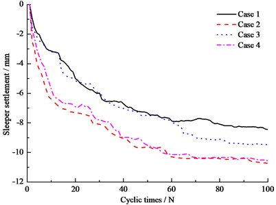
Fig. 9 shows the results of sleeper settlement during 100 cyclic loads. It is obvious that the results of Case 2, Case 3 and Case 4 are larger than Case 1, which means that the settlement of hanging sleeper settlement is always larger than normal supporting condition. The DEM analysis results match the FEM results well [5-6]. At the same time, it is meaningful to point out that sleeper settlement of Case 2 is the largest among all the simulation conditions, which illustrates that both ends of sleeper hanging is the worst condition for sleeper settlement. It should be noted that ballast tamping easily leads to the above Case 2 hanging sleeper situation, especially for the withdrawal of tamping operation, a small loss of compactness under the sleepers during withdrawal, where the ballast particles between sleeper ends are moved and produced the voids under sleeper, which increases possibility of hanging sleeper.
Fig. 9Sleeper settlement
3.3. Ballast breakage
Under the high frequency of railway load, dynamic impacting load affect ballast mechanics significantly. When the contact force is so large that ballast particles will break and wear. Ballast breakage is harmful to track structure, as small particles become the fouling source and can affect drainage. Contact bond was used to analyze ballast breakage in this paper. Fig. 10 presents the distribution of broken bonds in ballast bed, in which the yellow dots mean breakage caused by tension, and black dots represent breakage caused by shear force. It is clear that the majority of breakage appearance around the sleeper, to be more specific, under the sleeper, which was validated in field investigation and theoretical analysis [22].
Table 2Broken bonds number in different simulation conditions
Number of broken bonds | Case 1 | Case 2 | Case 3 | Case 4 |
Broken bonds caused by tension | 495 | 498 | 460 | 475 |
Broken bonds caused by shear force | 573 | 590 | 525 | 557 |
Total broken number | 1068 | 1088 | 985 | 1032 |
Fig. 11 shows the results of broken bonds of different simulation conditions. Fig. 11(a) is the results of total broken bonds, Fig. 11(b) is the amount of broken bonds caused by tension, and Fig. 11(c) is the amount of broken bonds caused by shear force. Table 2 lists the results of broken bonds after 100 cyclic loads. It is clear in Fig. 11(a), (b) and (c) that at the beginning, the number of broken bonds of ballast bed with hanging sleeper is larger than normal condition. The reason for the phenomenon is that the contact forces becomes more concentrated for hanging sleeper as investigated in 3.1 ballast contact force, so the breakage speed is faster than normal. The largest number of total broken bonds is Case 2, and then is Case 1, followed by Case 4 and Case 3. It is interesting to note that after 100 cyclic loading, the total number of broken bonds of hanging sleeper is not always larger than normal condition. It depends on the hanging area of sleeper. At the same time, it is noticeable that the number of broken bonds caused by shear force is always larger than that caused by tension. It could be concluded that the dynamic shear force is the main factor for ballast degradation, under train cyclic dynamic loads.
Fig. 10Distribution of broken bonds in ballast bed
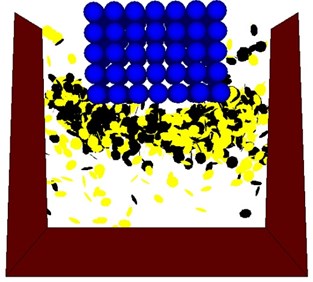
Fig. 11Statistics of broken bond
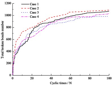
a) Total broken bonds number
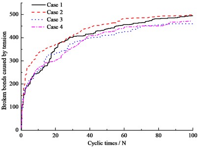
b) Broken bonds caused by tension
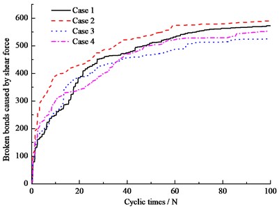
c) Broken bonds caused by shear force
3.4. Lateral ballast resistance
Lateral ballast resistance is determined by the resistance from bottom, crab and shoulder of sleeper [19]. When there is hanging sleeper, the contribution from sleeper bottom will decrease significantly. Lateral ballast resistance of different sleeper supporting conditions was analyzed in this paper. In the DEM model, an external lateral force was applied on the sleeper, then the resistance from bottom, crab and shoulder of sleeper was recorded, as well as sleeper displacement. Then after adding the resistance from three parts, lateral ballast resistance was obtained. At the same time, it is necessary to mention that during push the sleeper, the damping value was set 0.7, as it was a quasi-static process.
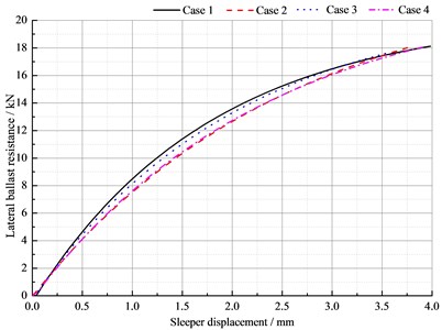
Fig. 12 shows lateral ballast resistance of different simulation conditions. It is clear that Case 1 representing normal sleeper has the largest lateral ballast resistance, while the results of hanging sleeper are smaller than this. When sleeper displacement is 2 mm, the lateral ballast resistance for four simulation cases was 13.576, 12.658, 13.281, 12.733 kN accordingly. It is interesting to note that both ends of sleeper hanging produce lateral ballast resistance reduction most significantly. The results are in accordance with the ballast lateral resistance contribution, signifying that the sleeper ends contact with ballast is of great importance both for lateral static stability and dynamic vertical response. In practice, the sleeper ends parts ballast should be well compacted, with ballast bed dimensions size assured.
Fig. 12Lateral ballast resistance
4. Conclusions
DEM has been used to examine the characteristics of hanging sleeper dynamic behavior. The irregular ballast particle was constructed by clusters to investigate the ballast particles breakage under dynamic loads. Ballast contact force, sleeper settlement, bond breakage and lateral ballast resistance were taken as indexes to evaluate the different hanging sleeper situations.
When sleeper hanging occurs, the maximum value of average contact force was reduced, while the minimum value of average contact force was increased. Results indicated that the level of vertical contact force, sleeper settlement, ballast degradation (bond breakage) depends on the hanging sleeper patterns, the dynamic ballast-sleeper interaction emphasized that engineering measures should be guaranteed, to secure the best distribution of stresses under the sleeper. Some ballasted track improvements should be considered in practice, such as increase thickness of ballast bed, use the PBI method to improve ballast compaction, and avoid ballast tamping produced void and non-contact. Results find that different hanging sleeper leads to variation of ballast resistance reduction.
In future, characterizing the dynamic behavior of granular ballast is one of the great challenges in the mechanics of track engineering, with aim to consider vehicle-ballasted track system. A coupled Discrete Element Method-Finite Element Method (DEM-FEM) code could be developed and implemented for analyzing the behavior of ballast granular layer under running train.
References
-
Sven A., Gerd G., Gerhard H., Schiinemannl A. Numerical model and laboratory tests on settlement of ballast track. System Dynamics and Long-Term Behaviour of Railway Vehicles, Track and Subgrade, Vol. 6, 2003, p. 317-336.
-
Grassie S. L., Cox S. J. Dynamic response of railway track with unsupported sleepers. Proceedings of the Institution of Mechanical Engineers, Part D: Transport Engineering, Vol. 199, Issue 2, 1985, p. 123-135.
-
Nielsen J. C. O., Igeland A. Vertical dynamic interaction between train and track-influence of wheel and track imperfections. Journal of Sound and Vibration, Vol. 187, Issue 5, 1995, p. 825-839.
-
Lundqvist A., Dahlberg T. Load impact on rail way track due to unsupported sleepers. Proceedings of the Institution of Mechanical Engineers, Part F: Journal of Rail and Rapid Transit, Vol. 219, Issue 2, 2005, p. 67-77.
-
Kaewunruen S., Remennikov A. M. Investigation of free vibrations of voided concrete sleepers in railway track system. Proceedings of the Institution of Mechanical Engineers, Part F, Journal of Rail and Rapid Transit, Vol. 221, Issue 4, 2007, p. 495-507.
-
Yang L. A., Powrie W., Priest J. A. Dynamic stress analysis of a ballasted railway track bed during train passage. Journal of Geotechnical and Geoenvironmental Engineering, Vol. 135, Issue 5, 2009, p. 680-689.
-
Shi J., Chan A. H., Burrow M. P. N. Influence of unsupported sleepers on the dynamic response of a heavy haul railway embankment. Proceedings of the Institution of Mechanical Engineers, Part F: Journal of Rail and Rapid Transit, Vol. 227, Issue 6, 2013, p. 657-667.
-
Sadeghi J., Hashemi F. Influences of rail support condition on mechanical behavior of railway track system. Transaction of the CSME, Vol. 32, Issue 3, 2008, p. 561-573.
-
Li S. Railway Sleeper Modelling with Deterministic and Non-Deterministic Support Conditions. Royal Institute of Technology, Stockholm, 2012.
-
Cundall P. A., Strack O. D. L. A discrete numerical model for granular assemblies. Geotechnique, Vol. 29, Issue 1, 1979, p. 47-65.
-
Lim W. L., McDowell G. R. Discrete element modeling of railway ballast. Granular Matter, Vol. 7, Issue 1, 2005, p. 19-29.
-
Lu M., McDowell G. R. The importance of modelling ballast particle shape in the discrete element method. Granular Matter, Vol. 9, Issue 1-2, 2007, p. 69-80.
-
Zamani N., EI Shamy U. DEM simulations of wave propagation in dry granular soils. Geo-Frontiers, 2011, p. 167-182.
-
EI Shamy U., Zamani N. DEM simulations of the seismic response of soil-foundation-structure systems. GeoCongress, 2012, p. 1730-1739.
-
Robertson D., Bolton M. D. DEM simulations of crushable grains and soils. 4th International Conference on the Micromechanics of Granular Media, 2001, p. 623-626.
-
Shao L., Chi S. C., Zhang Y., Tao J. Y. Study of triaxial shear tests for rockfill based on particle flow code. Rock and Soil Mechanics, Vol. 34, Issue 3, 2013, p. 711-720.
-
Lu M., McDowell G. R. Discrete element modelling of railway under monotonic and cyclic triaxial loading. Geotechnique, Vol. 60, Issue 6, 2010, p. 459-467.
-
Itasca Consulting Group, Inc. PFC3D (Particle Flow Code in Three Dimensions), Version 4.00, Minneapolis.
-
Gao L., Luo Q., Xu Y., Jiang H. K., Qu C. Effects of ballast bed section dimension on its lateral resistance. Journal of Southwest Jiaotong University, Vol. 49, Issue 6, 2014, p. 754-760.
-
Gao L., Luo Q., Xu Y., Ma C. S. Railway ballast bed mechanical property based on discrete element method. Journal of Tongji University, Vol. 42, Issue 7, 2014, p. 1064-1069.
-
Ehsan R. Vibrations of Partly Supported Concrete Railway Sleeper. Linköping University, Linköping, 2010.
-
Lim W. L. Mechanics of Railway Ballast Behaviour. University of Nottingham, Faculty of Engineering, Nottingham, 2004.
About this article

Research reported in this paper was supported by Beijing Natural Science Foundation (No. 8132037) and Fundamental Research Funds for Central Universities (2014JBM095).
