Abstract
Based on the elasticity theory, a differential equation of forced oscillation of the blade-casing system with rub-impact excitation was deduced, and the steady analytic solution was derived. The analytic solution was verified with the FE (finite element) method, the results indicated that the eigenvalues of dynamical equation by FE method are larger than the semi-analytical method’s, while the vibration modes are identical. Due to the characteristics of rub-impact excitation between the blade and casing, it is not suitable to solve impacting vibrational response for rotating blade with the steady analytic solution. Therefore, the semi-analytical solution was adopted to solve these dynamic problems, which can get the vibration response of any position for its continuity characteristic. Then, the FE and semi-analytical method is used. The comparison of dynamical response with changing speed, rub-impact depth and the friction coefficient was investigated in details. It is found that the speed has the greater effect on the dynamical vibration response, but other parameters affect the response slightly at the same rotational speed. When the friction coefficient and rub-impact depth unchanging, with the increasing speed, the contribution of each multi-frequency component to the resonant response grows obviously, especially the high-harmonic components should be pay more attention. Blade-casing model is easy to form a new resonance system, which will appear different resonant response with the increasing friction coefficient. When the friction coefficient reaches to a certain value, the response amplitude tends to be stable.
1. Introduction
In the modern aero-engine design, in order to improve the efficiency of aircraft engines, one of the important measures is to minimize the gap between the rotor and stator components. But as the clearance is reduced; the probability of rub-impact taking place during small changes in the operating conditions also increases. Therefore, the research of subject on the rub-impact between blade and casing become more and more significant. There are many scholars who have researched the problem in the past. And most people based on the cantilever beam model and cantilever plate model, considering the rotor system, the blade-case rub-impact boundary conditions, to establish rub-impact kinetic model. Padovan et al. [1] assumed the blade as a cantilever beam, the normal contact force was deduced with the blade of the radial deformation of the relationship, and analyzed the single leaf, leaf rubbing, unbalance, blade/rotor system stiffness, damping and the friction on the system nonlinear dynamic characteristics. Bauer [2] used the assumed modes method to investigate the vibrational behaviour of a rotating beam. Kane [3] studied the ZOAC classic model, analyzed the dynamic characteristics of the rotating flexible cantilever beam, found that this model can’t well describe the dynamic characteristics of the cantilever beam at high speed, and reported the dynamic stiffening effect for the first time. Kammer et al. [4] used perturbation method to study the dynamics and stability of a rotating Euler beam. Omprakash et al. [5] utilized the Love-Kichhoff method to study the effect on the natural frequency due to the blade stagger angle and twist angle in the rotor system. Sinha [6] studied with flexible rotor blades and rigid casing collision dynamics, regarded the blades as the rotating Euler-Bernoulli beam model, through additional stiffness matrix, damping matrix simulation Rub, found that when the tip in contact with the casing, like Hertz contact force generated by the contact force. Bo-Wun Huang [7] approximately regarded the blades as Euler-Bernoulli beam, used Hamilton’s principle to establish blade’s dynamical equations. After that, the paper investigated the effect on detuning under the influence of coupling effects between the blades and crack distribution system. Tai Xingyu [8] simplified the blade as a rotating cantilever beam model. In addition, the blade’s analytical model was deduced using Hamilton’s principle and variational principle, then considered the effect of centrifugal rigidization, spinning softening and Coriolis force. Sakar [9, 10] simplified the blades as beam model, discovered the local cracks might not only affect the blade’s dynamic behavior, but also cause severe mode localization. Chiu et al. [11, 12] analyzed the coupling vibrations under the influence of a long detuning blade rotor, and further investigated the effect on coupling vibrations among shaft-torsion, blade bending and lacking wire coupling vibrations of a multi-disk rotor system. Alain Batailly et al. [13] used Euler-Bernoulli beam to simulate blades, explored the dynamic behavior of Rub-impact. Cai G. et al. [14] used a similar model, and pointed out that the power of steel is essentially the problem of structural dynamics inertial system, the flexible beam is coupled by a rigid shaft for rotation and produce tiny elastic vibrations generated additional stiffness. Kouhai Jiang [15] established a dynamics model of cantilever plate attaching to a rotating rigid hub coupling system, rubbing faults between large rotating machinery blades and casing was studied.
In addition, the paper also researched the force model of Rub-impact. Padovan [1] and Choy [16] simplified a blade as a stationary cantilever beam after considering the blades’ large flexibility, and got the blade-casing rub-impact force model. Jiang [17] derived the blades-casing rub-impact force model which considered the impact of the rotating blades’ centrifugal force, thought that when the rub-impact fault occurs, there is an angle between blades and case, which will deduce the normal rub-impact force in the consideration of centrifugal force.
As can be seen from the references, it is that most references studied the rotating blades by using elasticity theory, then discrete the dynamical equation and calculated the numerical results, while the papers about the contrast between FE method and semi-analytical method are quite few. In this paper, on the basis of predecessors' work, continuous beam theory and FE theory are adopted to establish two kinds of dynamic models for a rotating-casing system, considering the influence of rub-impact , then two kinds of methods were compared to find out the differences, provide reference for research work in this field. This paper also provides a reference to solve the rubbing fault of aircraft engines.
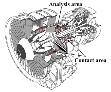
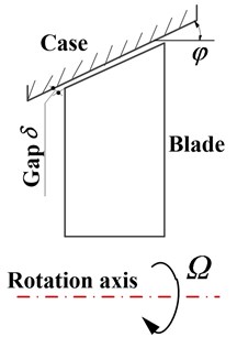
Fig. 1Schematic of rotating blades force environment
a)
b)
2. The dynamic model
Fig. 1(a) shows an aero engine profiles. In order to improve the efficiency of aircraft engines, one of the important measures taken is to minimize the gap between the rotor and stator components. But as the clearance is reduced; the probability of rub-impact taking place during small changes in the operating conditions also increases. The schematic of rotating blades force environment, as shown in Fig. 1(a), describe the sensitive parts of the compressor section of the region, in order to facilitate the analysis, here does not consider the impact of the shaft, the wheel, whirl and flow excitation force on the blade. Blades and casing can be simply expressed as rub-impact Fig. 1(b), the text will consider the influence of centrifugal force and friction force.
2.1. Rotating blades’ energy and reactive energy equation
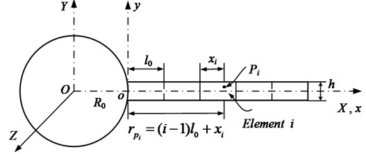
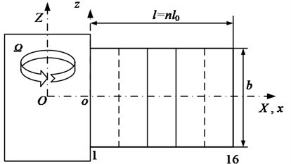
According to Fig. 1(b), established rotating cantilever blade-casing vibration system. In Fig. 2, - is the fixed coordinate system. - is the motional coordinate system. The blades rotate around axis at angular velocity. The radius of disk is , blade length is , the density of blade is , the elastic modulus is .
Fig. 2Blade model with Rub-impact
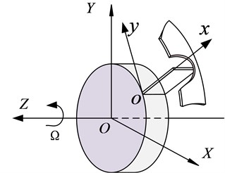
Here considers disk as a rigid plate, does not consider the disk strain energy. The kinetic energy and strain energy of a blade are showed in Eq. (1). Kinetic energy is produced by rotating of blades and bending of blades, potential energy includes bending potential energy and centrifugal potential energy:
where is the displacement of blades’ any position in the direction of , is the sectional moment of inertia of the blades, is the disk’s inertia. In order to study the vibration response of the rotating blade under the rub-impact force. Assuming rub-impact force is , the damping force generated by material is , and , the virtual work done by rub-impact forces and the damping force can be expressed:
where , equivalent viscous damping coefficient proportional is .
2.2. Blades-casing rub-impact force model
2.2.1. The normal rub-impact force
For the rotor rub-impact, it is generally believed as long as set the stiffness coefficient of the normal force model reasonably, while the linear method model of the normal force and the nonlinear model of the normal force are adopted, the effect on rub-impact dynamics of rotor and stator are quite few. So the rotor and stator rub-impact commonly used linear method to contact force model:
where is represent contact stiffness.
However, for the flexible blade rub-impact, blade-casing rub-impact condition is different; when rub-impact occurs, because of the flexibility of the blade is big, it is easy to cause the large deformation of the blade, this is different from the rub-impact between rotor and stator. So when considering rub-impact force that should be given consideration. When rub-impact occurs, considering a single blade and casing contact rub-impact force, Padovan and Choy [1] considered the blades as a stationary cantilever, got the rub-impact normal force of the blade-casing:
Jiang [17] derived the blades-casing rub-impact normal force model under the impact of centrifugal force when blades rotating, the model can consider blades at a certain angle with the happening of the casing of rub-impact. Blade forward for the Rub-impact, the normal rub-impact force can be expressed:
where means density, is cross-sectional area of the beam, means the angular velocity of rotation of blades, is Length of the blades, is flexural rigidity of blades, is the radius of disk, is displacement of the tip of the blades. And 1.549, 2.5.
According to the model proposed by Jiang, assumed the local deformation of the contact area is linear deformation, ignored frictional heat effects, tip-casing rub-impact conforms to the coulomb friction law. Friction coefficient is , there is a linear relationship with the weight of rub-impact force. So the tangential friction is , then established rotating blades-casing rub-impact model:
2.2.2. The process of rub-impact and reduction of rub-impact force
When the rotating blade and casing rub-impact occurs, the blade tip has a friction contact with the casing, Fig. 3 is the tip-casing gap model when the rotor and the casing of the axis in the wrong, dashed line in the circle part is the tip trajectory, the solid circle is geometry of the inside casing. The geometric center of casing is , the center of rotation of the blades rotor is , the radius of tip track is , the radius of casing is . tip clearance without eccentricity between rotor and casing is a constant value . During the rotating process of rotor at a speed of , has friction with blades in the position shown in Fig. 3, the eccentricity between the rotor and the casing is . Ignored the spanwise vibration and lateral vibration when blades rotating, then consider the contaction between the tip and casing is linear ramp load.
After studying the trajectory characteristics, can find: along with the rotation of the blade, when 0, rub-impact occurs, when 0, rub-impact does not occur. The biggest invasion depth is . This formula is deduced under the conditions of rub-impact occurring, the relationship of the initial gap and eccentricity should satisfy . When , can be obtained by former formula, tip and the casing does not rub-impact with each other. Assuming that the rotation angular velocity of the blade is , according to the geometric relationship, the invasion depth of function changing with time can be expressed as:
According to the theory of blades rub-impact, the changing law of rub-impact normal force is investigated in Fig. 4, which shows that the amplitude of rub-impact force increases with increasing rub-impact depth. When the rub-impact depth is 0.5 mm, the amplitude of rub-impact force reaches to 2.5 kN. When the rub-impact depth is 0.2 mm, the amplitude of rub-impact force reaches to about 1.8 kN. When the rub-impact depth is 0.1 mm, the amplitude of rub-impact force reaches to 1.5 kN. And as the increase of rub-impact depth, the rub-impact force increases quickly. And with the increase of invasion depth, the rub-impact time also increases.
Fig. 3Schematic of rotating blades-casing rubbing gap
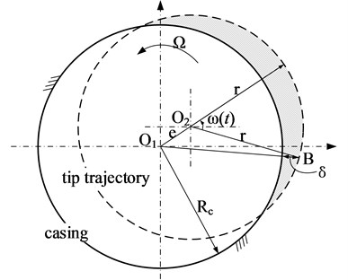
Fig. 4Contact force with different speed
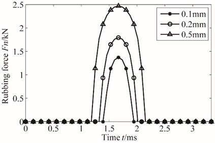
Fig. 4 shows that rub-impact force changing with rub-impact depth is similar to a half sine wave. Therefore, when specific application, the rub-impact force approximately simplified as periodic sine half-wave incentive, the rub-impact normal force function Eq. (6) can be simplified as the subsection sine half-wave function:
where 1, 2, 3,…, means amplitude, is a rub-impact action time, is the subsection sine impact cycles.
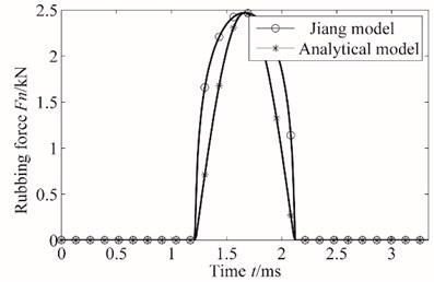
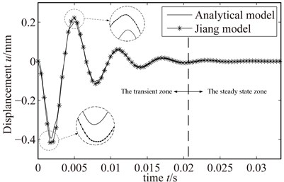
The curves of two types of rub-impact normal force, as shown in Fig. 5(a), show that semi-waveform is in agreement with the analytical waveform. Besides, this paper gives the response under the rub-impact force of Jiang model and analytical model in Fig. 5(b). Then, the error of response between Jiang model and analytical model is also shown in Fig. 5(b). As shown in Fig. 5(b), the responses under different rub-impact model are in good agreement. According Fig. 5(b), although the transient response error is bigger, while the steady state response error under different rub-impact model is enough small. So this paper can analytical model instead of Jiang model. Therefore, half-wave functioncan can be used in the concrete calculation.
Fig. 5The curves of two types of rub-impact normal force
a)
b)
2.3. Galerkin discretization of energy and the virtual work equation
Equations are discretized by using Galerkin method, A. Galerkin expansion:
where the first order of formation function , generalized coordinates is :
Eq. (9) into the Eq. (1), (2) to get:
In the Eq. (12), the first part is the bending strain energy, and the second part is the strain energy generated by the centrifugal force.
2.4. Forced vibration equations
For the convenience of description, here broadly defined rub-impact force as and damping force as . According to Lagrange equations, energy and the rotating blades of virtual work can be obtained:
According to Eq. (10), get the cantilever blade vibration differential equation:
Eq. (11) the generalized force vector does not include broad damping force , but more related with the damping matrix that comes from the damping force of virtual work. Damping matrix can be expressed as:
Generalized force vector can be expressed as:
3. Model validation
3.1. Validation of Galerkin method
As shown in Eq. (11), and the is infinite. So we have to give a reasonable value for the actual calculation, which is called Galerkin projection. And the computational accuracy depends on the appropriate value of parameter . Assume that the amplitude of response with can be expressed as , the error can be defined as , the parameter is a larger value (we take 10, 15, 20 here), so the errors , , can be found in Fig. 6.
Fig. 6Response error of Galerkin projection
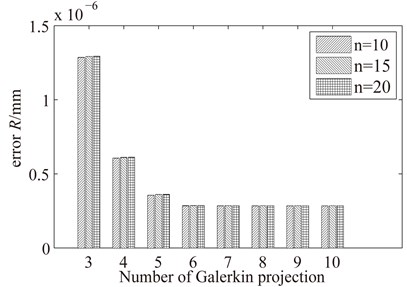
According to the results in Fig. 6, when the number of Galerkin projection , the relative response error with 10, 15 and 20, respectively is virtually unchanged. According to Fig. 6, the term 6 is enough to yield an accuracy up to 10-6 mm, so it is enough accurate to research the rubbing fault.
3.2. The validation of model
Now, specific parameters were given to verify the validation of blade model. Elastic modulus of blade is 2.06 GPa, density is 7850 m3, blade length is 0.1 m, blade disk radius is 0.1 m, the damping coefficient is 100 N/m⋅s. In order to verify the correctness of vibration response under rub-impact load on the blades, the results of FEM and semi-analytical methods are compared, unit division of FEM is shown in Fig. 7. Besides, the shape function of FEM is given in Eq. (17).
The shape function of the beam element:
Fig. 7Finite element model of cantilever beam
a)
b)
The calculation results of natural frequency in the paper and the calculation with the FEM are given in Fig. 8(a) and the normalized model of two algorithms are shown in Fig. 7(b).
As is shown in the figure, the natural frequency and mode shape of blade got by Semi-analytical method and FEM are basically identical, slightly larger than the FE method at high speed, results can prove that the derivation from the figure of rotating blade vibration equation is correct.
Fig. 8Rotating blades
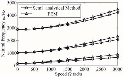
a) Natural frequencies
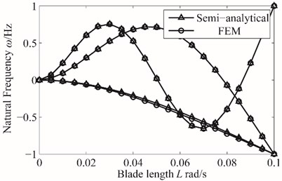
b) Mode shapes
4. The verification for analytical solution of forced vibration
4.1. Fourier series expansion of rub-impact force
According to the simplified rub-impact force theory, transform the rub-impact force by Fourier, expanded in Fourier series form:
where:
In Eq. (3), rub-impact force can be expressed as:
where is a Dirac function, it is used to control rub-impact location. is the position of rub-impact. is friction coefficient.
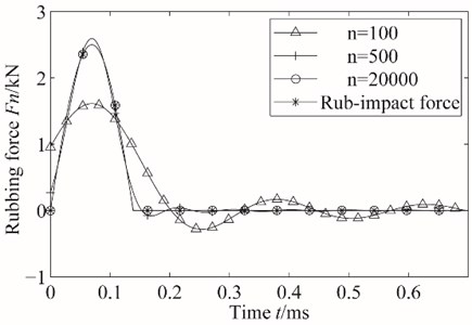
In order to verify the accuracy of rub-impact force after Fourier transform, Fourier transform of order n take 100, 500 and 20000 respectively. Then the three cases of rub-impact force compared with the actual rub-impact force in Fig. 9. According to the results, we can find that when Fourier transform take a larger order, the approximate rub-impact force function can achieve good approximation degree, however, computation time is too long, can’t meet our requirement for computational efficiency. Through comparision and analysis, when 20000 is enough to achieve computational efficiency and the demand for accurancy.
Fig. 9Contrast between actual rub-impact force and rub-impact force after Fourier transform
4.2. Response solution for Rub-impact
4.2.1. The derivation of analytical solution
Eq. (16) can be further simplified as:
According to damping forced vibration theory under harmonic excitation and Eq. (20), analytical solutions of the rotating blade’s differential equations under the rub-impact force can be obtained:
where:
Because usually rub-impact occurs at the end of the blade, .
4.2.2. The comparison of analytical solution and semi-analytical solution
Analytical results rub-impact are shown in Fig. 10. The condition contains that speed is 1200 r/min, rub-impact depth is 0.005 mm, damping is 200 N/m⋅s, friction coefficient is 0.3. And according to Eq. (21), we can get the analytical result. And we can get the semi-analytical result by Newmark-.
Fig. 10The analytical result of rub-impact
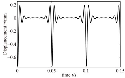
Fig. 11The semi-analytical result of rub-impact
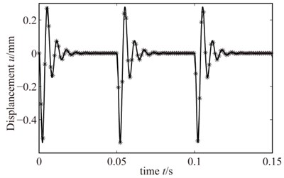
Accorng to Figs. (10), (11), it can be seen that: since in the process of solving the analytical solution of blades mading a Fourier transform, so the analytical solution to a large extent affected by the harmonic function periodically. Then, there is a symmetrical effect for analytical solution which can not be eliminated. Due to the characteristics of rub-impact, when the rub-impact occurs, there is no bilateral effect. Thus significantly affects the precision of the analytical solution. Therefore, only semi-analytic results were compared with the FE results in the subsequent analysis. So in the next study, we can only research the rub-impact fault by semi-analytical method in order to keep the calculation accuracy.
5. The effect of different parameters on rub-impact response
To study the effect of different parameters on the two methods, and the effect of different parameters on the rub-impact response. This section presents rub-impact response under different speed, rub-impact depth and friction coefficient, the three-dimensional waterfall under different conditions are given, and the results are analyzed.
5.1. Dynamic response of blades under different speed
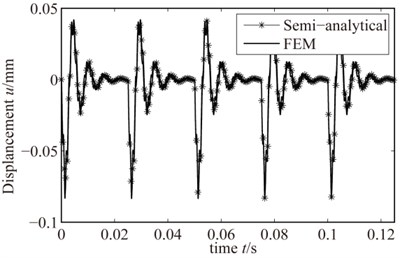
The Semi-analytical result and the result though the FE method of rotating blades – casing rub-impact vibration response are shown in Fig. 12 and Fig. 13, respectively. In the calculation, the rotating speed are 1200 r/min and 2400 r/m, and rub-impact depth and friction coefficient are set to be 0.001 mm and 0.3, respectively. Though the analysis, it shows that two methods of solving the rub-impact response has good consistency. When rotating speed is low, the numerical results of rub-impact response is basically identical with the solutions of FEM; and when rotating speed is large, numerical results and FE results have slight differences, however, the results obtained by the two methods have a consistent trend; Additionally, we can also find, when the rotating speed is low, a period of blade rub-impact response soon decay to a steady state, while under high rotating speed, the blades rub-impact response go into the next transient vibration period without decay to a steady-state. So for the rub-impact fault of rotating blades, we should be more concerned about the transient rub-impact response. In addition, the amplitude of the rub-impact response got by FEM is slightly smaller than that of the semi-analytical results, and the phenomenon is more and more obvious as the increase of the rotational speed. It explains the FE model is more rigid compared to some of the semi-analytical model.
Fig. 12Rub-impact response when 1200 r/min
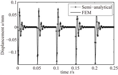
Fig. 13Rub-impact response when 2400 r/min
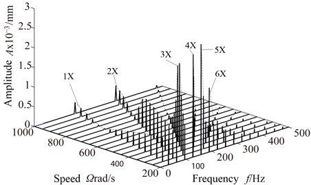
To study the effect of rotating speed on the blade rub-impact vibration response, and get more response characteristics, Fig. 14 is three-dimensional waterfall diagram of the tip position under the increasing speed condition. From the 3D waterfall Fig. 13 can be found, 1 component of rub-impact response amplitude increase first, then the decrease. 2 component of rub-impact response amplitude basically remains unchanged when rotation speed is less than 600 rad/s, then increases. They all get the smallest results at 750 rad/s. Respectively, rub-impact amplitude of 3, 4, 5 get a peak in the speed near 350 rad/s, 250 rad/s, 200 rad/s, then show a decreasing trend. This is because excitation frequency formed by these multiplier is so close to natural frequency that vibration amplitude appear in the ingredients. Therefore, enough attention should be taken to the resonant response caused by the high octave.
Fig. 14Waterfall with speed changes
5.2. Dynamic response of blades under different rub-impact depth
Fig. 15 and Fig. 16 show the semi-analytical and FE results when the rub-impact depth is 0.001 mm and 0.005 mm, respectively, and the rotating speed is set to be 1800 r/min and friction coefficient is set to be 0.3. It can be found that the semi-analytical method and FEM of solving the rub-impact response have good consistency. When rub-impact depth is slightly large, rub-impact response of semi-analytical results and FE results have great consistency; when rub-impact depth is small, the semi-analytical results and FE results have slight differences. However, the results obtained by the two types of methods have a consistent trend, and with the increase of the rub-impact depth, the blade vibration amplitude also increases.
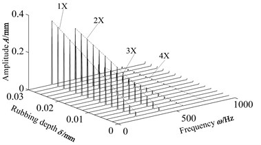
Figs. 17 and 18 respectively give the waterfall diagrams with the change of rub-impact depth when the speed are 1800 r/min and 12000 r/min. When the rotating speed is 1800 r/min, 3 occurs the rub-impact response peak when the rub-impact depth is 0.01 mm, 5 and 6 occur rub-impact response peak when the rub-impact is 0.009 mm, and 1 and 2 do not cause excessive vibration amplitude. When the rotating speed is 12000 r/min, vibration amplitude of 1 and 2 ingredients increase with the increase of rub-impact depth. 3 and 4 also show a increasing trend, but the vibration amplitude is small. It is mainly caused by forced vibration response. And it is so far from the natural frequency that the vibration amplitude is relatively small. Two kinds of speed waterfall figure contrast can be seen, more attention should be focused on high-octave ingredients at low-speed, and due to the effect of the rub-impact depth, will appear different resonant response with the increasing friction coefficient.
Fig. 15Rub-impact response when the rub-impact depth is 0.001 mm
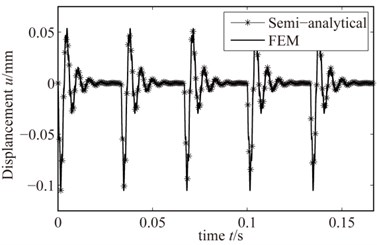
Fig. 16Rub-impact response when the rub-impact depth is 0.005 mm
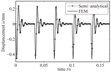
Fig. 17Waterfall with the rub-impact depth changes when 1800r/min
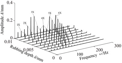
Fig. 18Waterfall with the rub-impact depth changes when 12000 r/min
5.3. The blade dynamic response of different friction coefficient
The rotating speed and rub-impact depth are set to be 1800 r/min, 0.005 mm. By two solving methods, Fig. 19 and Fig. 20 shows the semi-analytical and FE results when the friction coefficient is 0.05 and 0.3, respectively. From the comparison: as the change of the friction coefficient, two methods of solving the rub-impact response still have good consistency and accuracy. When the friction coefficient is large, the response of the blade tip slightly increases.
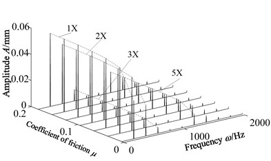
Fig. 21 and Fig. 22 respectively give the waterfall diagrams with the change of friction coefficient when the speed is 1800 r/min and 12000 r/min. With the increase of friction coefficient, blade vibration amplitude increases ,however, the change is obvious only when the friction coefficient is small. At the low speed 1800 r/min, blade vibration amplitude changes very slowly when the friction coefficient is greater than 0.1. Blade vibration amplitude changes slower when the friction coefficient is greater than 0.06.
At high speed 12000 r/min, as the same as low speed, for larger amplitude multiplier ingredients, blade vibration amplitude changes very slowly when the friction coefficient is greater than 0.1, and for smaller amplitude multiplier ingredients. For the frequency component of small amplitude, blade vibration amplitude changes very slowly when the friction coefficient is greater than 0.06. Two speeds of vibration, and low-speed and high octave amplitude is large, high speed, low octave amplitude is large.
Fig. 19Rub-impact response when friction coefficient is 0.05
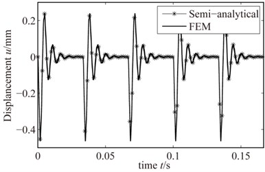
Fig. 20Rub-impact response when friction coefficient is 0.3
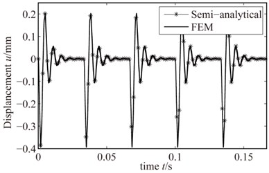
Fig. 21Waterfall with friction coefficient changes when 1800 r/min
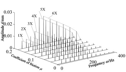
Fig. 22Waterfall with friction coefficient changes when 12000 r/min
6. Conclusion
In this paper, the steady vibration response of a rigid plate-rotating blades system under rub-impact force is researched, found that:
1) There is a certain error between the results of semi-analytical method and FEM; The FEM and the semi-analytical method have good consistency when the speed is low; There are larger errors for the two methods when the speed is high, and eigenvalues got by FEM slightly larger than that got by semi-analytical methods, modes are exactly consistent, while semi-analytical method has the characteristics of continuity for the rub-impact response.
2) With the increase of speed, rub-impact depth, friction coefficient, two methods of solving the rub-impact response have the very good consistency and accuracy, but at high speed, there is a certain error; More attention should be paid to the high-frequency components of the blade rub-impact, and it is easy to cause resonance response.
3) Under the condition of the given speed and friction coefficient, with the increase of the rub-impact depth, blade vibration amplitude are also growing; When the speed is high, blade spectrum frequency composition is more complicated, will appear different resonant response under the same frequency.
4) Friction coefficient has little effect on amplitude of vibration response, but when the friction coefficient increases to a certain extent, the amplitude of each octave change lowly, and the turning point of large vibration amplitude component is later than that of small vibration amplitude component.
References
-
Padovan J., Choy F. K. Nonlinear dynamics of rotor/blade/casing rub interactions. Journal of Turbomachinery, Vol. 109, Issue 4, 1987, p. 527-534.
-
Bauer H. F., Eidel W. Vibration of a rotating uniform beam, part II: orientation perpendicular to the axis of rotation. Journal of Sound and Vibration, Vol. 122, Issue 2, 1988, p. 357-375.
-
Kane T. R., Ryan R., Banerjee A. K. Dynamics of a cantilever beam attached to a moving base. Journal of Guidance, Control, and Dynamics, Vol. 10, Issue 2, 1987, p. 139-151.
-
Kammer D. C., Schlack A. L. Effects of nonconstant spin rate on the vibration of a rotating beam. Journal of Applied Mechanics, Vol. 54, Issue 2, 1987, p. 305-310.
-
Omprakash V., Ramamurti V. Coupled free vibration characteristics of rotating tuned bladed disk systems. Journal of Sound and Vibration, Vol. 140, Issue 3, 1990, p. 413-435.
-
Sinha S. K. Dynamic characteristics of a flexible bladed-rotor with Coulomb damping due to tip-rub. Journal of Sound and Vibration, Vol. 273, Issue 4, 2004, p. 875-919.
-
Huang B. W. Effect of number of blades and distribution of cracks on vibration localization in a cracked pre-twisted blade system. International Journal of Mechanical Sciences, Vol. 48, Issue 1, 2006, p. 1-10.
-
Tai X. Y., Ma H., Tan Z., Wen B. C. Dynamic characteristics of a continuous rotating beam model with a rubbing fault. Journal of Vibration and Shock, 2009.
-
Şakar G., Sabuncu M. Dynamic stability of a rotating asymmetric cross-section blade subjected to an axial periodic force. International Journal of Mechanical Sciences, Vol. 45, Issue 9, 2003, p. 1467-1482.
-
Sakar G, Mustafa S. Buckling and dynamic stability of a rotating pretwisted asymmetric cross-section blade subjected to an axial periodic force. Finite Elements in Analysis and Design, Vol. 40, Issue 11, 2004, p. 1399-1415.
-
Chiu Y. J., Huang S. C. The influence on coupling vibration of a rotor system due to a mistuned blade length. International Journal of Mechanical Sciences, Vol. 49, Issue 4, 2007, p. 522-532.
-
Chiu Y. J., Yang C. H. The coupled vibration in a rotating multi-disk rotor system with grouped blades. Journal of Mechanical Science and Technology, Vol. 28, Issue 5, 2014, p. 1653-1662.
-
Batailly A., Legrand M., Millecamps A., et al. Numerical-experimental comparison in the simulation of rotor/stator interaction through blade-tip/abradable coating contact. Journal of Engineering for Gas Turbines and Power, Vol. 134, Issue 8, 2012, p. 082504.
-
Cai G. P., Hong J. Z., Yang S. X. Dynamic analysis of a flexible hub-beam system with tip mass. Mechanics Research Communications, Vol. 32, Issue 2, 2005, p. 173-190.
-
Yuan H. K. H., Wu B. W. W. study on rubbing dynamic behavior of hub-plate with analytical method. Chinese Journal of Solid Mechanics, Vol. 2, 2013.
-
Li D. X., Chen J. Natural frequency characteristics and dynamic stress of a blade in an axial-flow compressor. Zhendong yu Chongji (Journal of Vibration and Shock), Vol. 30, Issue 7, 2011, p. 138-142.
-
Ahrens Jang, Ulbrich H., Ahaus G. Measurement of contact forces during blade rubbing. Professional Engineering Publishing, 1998, p. 259-268.
About this article

The project was supported by Fundamental Research Funds for the Central Universities (Nos. N140304002, N140301001) and the China Natural Science Funds (No. 51105063).
