Abstract
The common technique frequently employed in dynamic stress analysis of vibration systems is time-consuming and difficult to solve when dealing with the dynamic systems with nonlinear contacts, such as turbine blades subjected to rubbing faults. To address this deficiency, an approach combining the incremental harmonic balance (IHB) method with the finite element method (FEM) was proposed for predicting the dynamic stress of rubbing blades. First, the finite element model of a warp three-dimensional (3D) entity blade was developed, and its dynamic equation was established by considering the effect of centrifugal force under high speed revolution. Then, as the rubbing fault is highly nonlinear and strong coupling, the IHB method was applied to solve the periodic solutions of the system, and the deformation of each node was obtained. Third, taking the deformation response obtained as initial displacement constraints and imposing it on relevant points, the dynamic stresses were then obtained by using the static analysis in ANSYS. Since employing the IHB method, the transient nonlinear finite element analysis was transformed into the static analysis in the present method, so it significantly raised the solution efficiency. To show the effectiveness of the method, dynamic stress prediction and parameter analysis of a rubbing blade were studied as an example.
1. Introduction
Blade, as one of the key parts of turbomachinery, will generate large tensile and bending stress due to large centrifugal force when rotating at high speed. Blade rupture fault happens occasionally on account of fatigue damage accumulation because it sustains alternating stress for a long time. Thereby the dynamic stress on blades, especially in faults, must be analyzed to guarantee safe and stable operation of rotating machinery. Moreover, accurate prediction of stress on blade surface is of significance in turbine blade design and optimization [1-3].
Rubbing is known to be a serious malfunction in turbomachinery [4], due to the small clearance between the blade and the casing; it is also a main cause of instability of rotor systems. Once rubbing occurs, complex nonlinear vibration and a series of kickbacks will be initiated; dynamic stress on each part and the key angular points of blade will also be affected. The dynamic stress of rubbing blade must therefore be determined accurately.
In the past years, a large amount of research on rubbing fault have been investigated and a detailed overview is provided in [5, 6]. Rich and complex phenomena and characteristics induced by rubbing have been found in these studies, which include: bifurcation and chaos [7], periodic and quasi-periodic vibrations [8], sub-harmonic and super-harmonic vibrations [9-11], etc. Although the vibration behavior and dynamic characteristics induced by rubbing have been previously studied [7-13], that of dynamic stress on rubbing blades is still inadequate. Fewer studies have investigated this problem because of its complexity.
To calculate distribution of stress, the most commonly used method is the FEM. With developing computer technology, ANSYS has become a powerful analysis tool, which is frequently performed to conduct a 3D-numerical simulation and calculate distribution of stress using the FEM commercial codes. In terms of predicting the dynamic stress on blades, Daniel [14] investigated the effects of ceramic thermal coating on the dynamic stress distribution on a blade using the FEM. About the fault working condition, Poursaeidi [15] applied the FEM to analyze the response of a 3D blade model to the effects of static force and dynamic force, and the simulation results have shown that the region of high stress occurs in the initial crack location. A complex stress and crack initiation analysis of a PZL-10W turbo-engine compressor blade subjected to high cycle fatigue was conducted by utilizing a nonlinear FEM [16], etc.
The above analysis primarily used the FEM in ANSYS directly to analyze the dynamic stress; and model modification was adopted in the blade with initial cracks. Nevertheless, rubbing fault as a type of contact problem with high nonlinearity, it cannot be solved directly to determine the dynamic stress through simple model modification. Although the FEM can solve for dynamic stress, it is much difficult and time-consuming when obtaining the steady-state response of a contact rubbing problem.
So in our study, we proposed a method that combines the IHB method [17-20] with the FEM to predict the dynamic stress and deformation of rubbing blades. Meanwhile, a new way for imposing the centrifugal force was applied in our research. By introducing the IHB method, an efficient tool available to analyze the steady-state response of the rubbing contact problem, the transient finite element analysis is transformed into static analysis in the method. Thereby, the efficiency of this method improves significantly for dynamic stress prediction. Furthermore, dynamic stress prediction of a rubbing blade and influence analysis of the tip rubbing fault and rubbing parameters were studied to show the effectiveness of this method.
2. Dynamic modeling
2.1. Centrifugal forces
The modern turbomachinery has characteristics of large-scale and high speed. When the rotor rotates in high-speed, a quite small unbalance can cause quite large centrifugal inertial forces. Therefore, the effect of centrifugal forces on dynamic analysis of blade-rotor systems is indispensable. However, the mathematical model of centrifugal force vector must be given in order to solve conveniently by using the analytic method. So in our study, we proposed a method for obtaining the centrifugal force vector.
Firstly, establishing the finite element model of the blade, and a modal analysis is conducted to export the Harwell-Boeing matrices, which can be formed into the mass matrix , the damping matrix , and the stiffness matrix using the matrix assembly techniques. Then, applying a rotating speed along axial direction, the static deformation of the rotating blade is obtained through a static analysis in ANSYS. Lastly, the centrifugal force vector is follow obtained by .
2.2. Rubbing forces
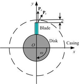
To improve the performance and efficiency of rotating machinery, a widely used way is to reduce the clearance between the blade and the casing. However, the rubbing fault is being liable to happen thereupon. In the paper, a schema of blade-casing rubbing is depicted in Fig. 1, in which is the static clearance between the moving blade and the static casing. The blade-casing rubbing fault will happen when the radial displacement of blade tip exceeds e with the effects of centrifugal forces at a rotation speed or other factors (misalignment, thermal bending, etc.).
In our study, the fixed-point rubbing is taken into account. The rubbing force is denoted by the piecewise-linear elastic model. The nonlinear resilience can be expressed as the following:
where is the nonlinear contact stiffness; is the rubbing clearance.
Assuming that there is only one rubbing location at the th DOF in the totally DOFs system, the rubbing force vector can be described as:
Fig. 1Schema of the blade-casing rubbing
2.3. Dynamic model of the rubbing blade system
Considering the effects of rubbing and centrifugal forces, the differential equation of motion of a rotating rubbing blade system can be written as follow:
where , , and respectively denote the mass matrix, the damping matrix, the stiffness matrix, and the displacement vector of the system; is the centrifugal force vector; and is the rubbing force vector. The dynamic model of the rubbing blade is now established for finding a solution of the system.
3. Methodological details
3.1. Dynamic stress prediction method
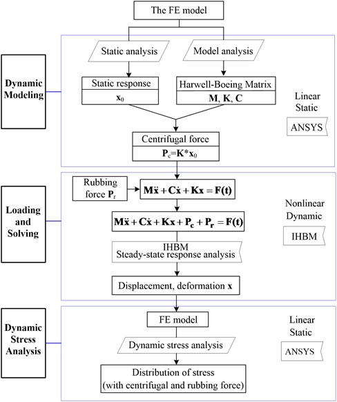
In this section, we present a new way for predicting the dynamic stress on a rubbing blade, which combines the IHB method with the FEM. To describe more clearly, the algorithm flow diagram is established as shown in Fig. 2, and it can be detailed into the following three steps of the solution procedure.
First, dynamic modeling: according to the method referring in Section 2.1, form matrices , , , and static response of the system, and the centrifugal force vector is then obtained by ; the nonlinear equation of motion of the blade system is established by using Lagrange equation considering the effect of centrifugal force and rubbing force, seeing in Section 2.3.
Next, loading and response solving: the steady-state response at any time of the differential equation was solved by applying the IHB method, that is the transient displacement and deformation at each node of the rubbing blade, is obtained;
Third, dynamic stress determination: taking the transient displacement at each node obtained as initial displacement constraints, imposing the deformation of each point on corresponding node of the blade, then the dynamic stress at any time and location can be predicted through a static analysis in ANSYS, whereas accounting for the effects of centrifugal force and rubbing force.
Since the transient finite element analysis is transformed into the static analysis in the present method, it significantly raises the solution efficiency. Moreover, compared to the numerical integration method employed in ANSYS, the IHB method can easily and directly solve the steady-state response of strongly nonlinear vibrations.
Fig. 2Algorithm flow diagram for dynamic stress prediction of rubbing blades
3.2. IHB method
As the IHB method is an effective tool for obtaining periodic solutions of strongly nonlinear multi-DOF systems, which is applied to conduct the rubbing problem to improve the efficiency of the prediction method.
In this subsection, the IHB method is formulated to analyze DOF nonlinear system vibrations. The dynamic equation of motion of a rubbing blade system is generally expressed as:
where a dot denotes differentiation with respect to the new dimensionless time variable , which is defined as ; the connotations of symbols in the equation as what mentioned before in Eq. (3).
Considering the steady-state response of Eq. (4) and supposing the base frequency of the response is , and is a positive integer. Considering the th order harmonic, the response of node can be expanded to the form of a Fourier series:
All solutions of the DOF system are , where denotes the th harmonic of .
Supposing is the increment of yields:
Then, from Eq. (5), the following can be obtained:
where:
Let and . Therefore, , and all compositions of unknown quantity are the following:
Substituting Eq. (6) into Eq. (4) and neglecting the high-order harmonic components, this yields:
where and .
Assume that is the variation of . Applying the Galerkin’s method, Eq. (9) yields:
Let , , , , and . Based on the variation characteristic, Eq. (4) can be rewritten as:
where:
can be solved from Eq. (11) iteratively, following which can be obtained.
4. Results and discussions
The moving blade is one of the main components of axial compressors, steam turbines, and aero-engines. It operates at high rotational velocities, and it is damaged most easily because of the nonlinear vibrations caused by complex excitations. It is important to analyze its vibration characteristics and stress distribution of the moving blade.
In this section, dynamic stress prediction of a rubbing blade with centrifugal force was investigated to demonstrate the effectiveness of the present method. Furthermore, influence analysis of the rubbing parameters (contact stiffness and rubbing clearance) on stress distribution were studied by using this method. In the next simulation process, eight harmonic terms were adopted to solve the steady-state response by using the IHB method.
4.1. Finite element analysis model of the blade
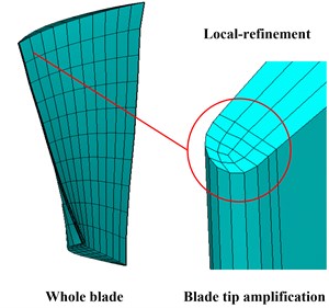
In the paper, the finite element model of a twisted 3D blade was developed by using the ANSA, as shown in Fig. 3. In order to calculate more precise, local mesh refinement at blade edges was adopted. Assuming the rotating speed of the blade is 10000 rpm and its material parameters are detailed in Table 1. The finite element model is divided into 1023 nodes with 720 Solid185 elements, which has three DOFs at each node: translations in the nodal , and directions.
Table 1Material parameters of the blade
Elasticity modulus (N/m) | Poisson ratio | Density (kg/m3) | (MPa) | (MPa) |
2.1×10¹¹ | 0.3 | 7850 | 760 | 860 |
Fig. 3Finite element model of the blade
4.2. Algorithm verification
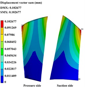
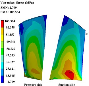
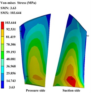
To illustrate the precise of the present method, contrast verification has been carried out. Figs. 4 and 5 show the deformation and stress distribution of the blade with centrifugal force obtained from the ANSYS directly and the present method, respectively. Precise comparison of the two methods is detailed in Table 2.
Table 2Precise comparison between the ANSYS and the present method
Item / method | ANSYS | Present method | Error percentage |
Maximum deformation (mm) | 0.102677 | 0.103013 | 0.327 % |
Maximum stress value (MPa) | 103.564 | 103.644 | 0.077 % |
There are 0.327 % and 0.077 % error percentage in the maximum value of deformation and stress obtained from the present method compare to the ANSYS. The tiny error generally can be neglected and it may be caused by truncation error of calculation, which depends on the selected harmonic terms in the IHB method. Comparison with the ANSYS shows that the calculation results are almost identical, which indicates that this method is a feasible one.
Fig. 4Deformation and stress distribution of the blade with centrifugal force obtain by ANSYS
a) Deformation
b) Stress distribution
Fig. 5Deformation and stress distribution of the blade with centrifugal force obtain by the present method
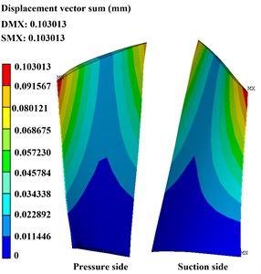
a) Deformation
b) Stress distribution
4.3. Effect of contact stiffness
The nonlinear contact stiffness is an important rubbing parameter that can affect the severity of rubbing fault. In this subsection, we firstly study the effects of nonlinear contact stiffness on stress distribution of the system, so the rubbing clearance is fixed as 0.015 mm. Periodic solutions are solved by using the IHB method, and then stress distributions of the rubbing blade surface are obtained by the present prediction method. Assuming that the rubbing contact occurs at the left blade tip in the pressure side, which is the max deformation location; the time-domain waveforms of the rubbing node are shown in Fig. 6(a) and the Von-Mises stress of the blade with different contact stiffness are shown in Fig. 6(b) to (d) which corresponding to 1×10³ N/mm, 2×10³ N/mm, and 3×10³ N/mm.
As shown in Fig. 6(a), the obvious distortion is induced by the blade tip rubbing fault in time-domain waveforms. More concretely, the amplitude amplification on one side happens with relatively smaller contact stiffness, whereas the wave clipping phenomenon on one side appears with relatively larger contact stiffness.
It is also found that, from Fig. 6(b) to (d), when the contact stiffness reaches 1×10³ N/mm, stress distribution on blade surface changes seriously due to the rubbing fault. The max Von-Mises stress on the whole blade surface increases about 100 MPa when the contact stiffness increases by 1×10³ N/mm; the max value on blade tip changes from 103.978 MPa to 329.324 MPa when the contact stiffness reaches into 3×10³ N/mm; the high stress area changes from the blade root location to the blade tip location. It is noted that the regions of high stress and dangerous points may occur not only at the blade root but also the blade tip locations.
Fig. 6Time-domain waveforms and distribution of Von-Mises stress with different contact stiffness
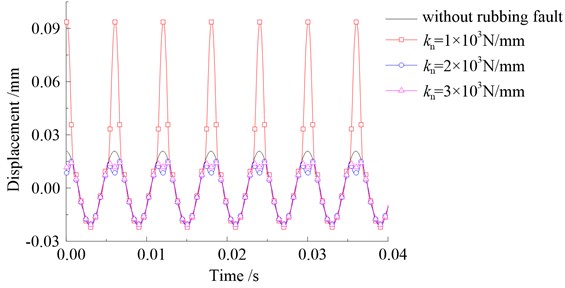
a)
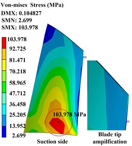
b)1×10³ N/mm
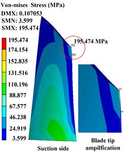
c)2×10³ N/mm
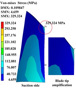
d)3×10³ N/mm
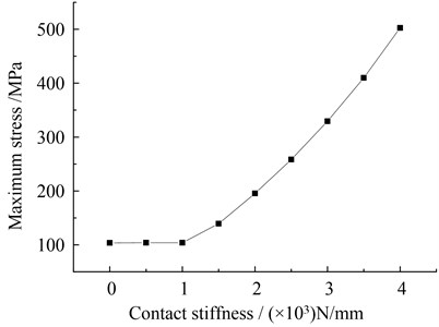
To demonstrate more clearly, the maximum Von-Mises stress curves with different contact stiffness are depicted in Fig. 7. As noted that the max value of the Von-Mises stress becomes larger with the increasing contact stiffness after the rubbing fault occur. It also indicates that the maximum value of Von-Mises stress becomes higher obviously when the rubbing fault becomes more serious.
Fig. 7Maximum Von-Mises stress curves with different contact stiffness
4.4. Effect of rubbing clearance
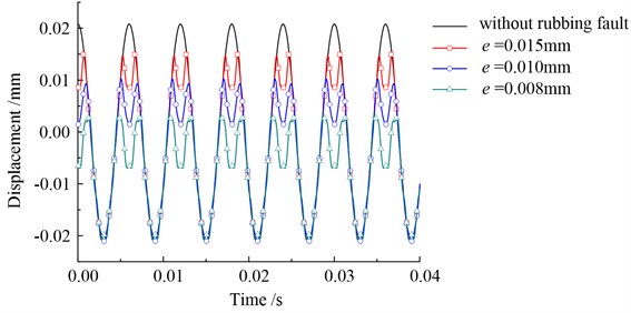
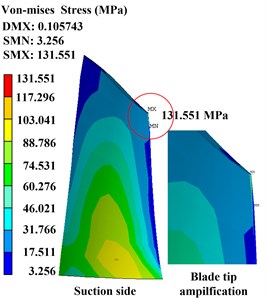
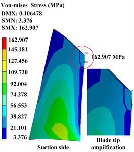
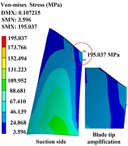
Moreover, the rubbing clearance is another key rubbing parameter, the effect of it on stress distribution is investigated in this subsection. It also assumed that the rubbing contact occurs at the same location, with a contact stiffness of 1×10³ N/mm. Fig. 8(a) displays the time-domain waveforms of the rubbing node with different rubbing clearances of 0.015 mm, 0.010 mm, and 0.008 mm. Fig. 8(b) to (d) presents the Von-Mises stress of the blade with different rubbing clearances of 0.012 mm, 0.010 mm, and 0.008 mm, respectively.
It can be seen from Fig. 8(a) that the wave clipping phenomenon on one side appears more serve with the rubbing clearance becomes smaller; the clearance can also seriously affect the distribution of stress on blade: the max stress on blade surfaces increases from 131.551 MPa to 195.037 MPa with the rubbing clearance changing from 0.012 mm to 0.008 mm; the max stress increases about 30 MPa when the rubbing clearance decreases by 0.002 mm. More obviously, the region of high stress also appears from the blade root location to the blade tip location.
Fig. 8Time-domain waveforms and distribution of Von-Mises stress with different rubbing clearance
a)
b)0.012 mm
c)0.010 mm
d)0.008 mm
Additionally, Fig. 9 displays the max Von-Mises stress curves of the blade with different rubbing clearances. As shown in the graph, the max stress on the blade displays a decreasing tendency with the increase in rubbing clearance. Due to that the rubbing fault is being liable to happen with the decreasing rotor-stator clearance, that is, the dynamic stress becomes larger when the rubbing fault becomes more serious.
4.5. Discussions
Here, we conduct numerical experiments for predicting dynamic stress of a rubbing blade by using the present method. From the preceding analysis, we can infer that the method is an efficient tool for performing dynamic stress analysis of rubbing blades, which combines the IHB method with the traditional FEM and therefore can save time required for solving the nonlinear steady-state response of systems. The advantage of this prediction method is high-efficiency.
Fig. 9Maximum Von-Mises stress curves with different rubbing clearance
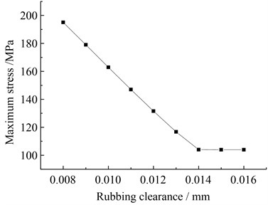
Moreover, the above numerical experiments denote that the blade tip rubbing fault can seriously affect the distribution of stress on blade surfaces. The max Von-Mises stress on the whole blade surface increases about 100 MPa when the contact stiffness increases 1×10³ N/mm; and it also increases about 30 MPa when the rubbing clearance decreases by 0.002 mm. It shows that the stress on blade increases sharply with the rubbing fault becomes serious; the region of high stress occurs from the blade root location to the blade tip rubbing location. Blade tip rubbing fault will not only induce complex nonlinear vibration, but also can cause plastic deformation and even break off if there is an initial crack on the blade, its stress distribution therefore should be predicted accurately. Meanwhile, the stress variation on the part of blade tip and blade root caused by rubbing fault should be given especially notice; it can also provide guidance of strength design according to the stress value in dangerous points.
5. Conclusions
In this study, an approach combing the IHB method with the FEM was presented for predicting the dynamic stress on rubbing blades. Dynamic stress prediction and parametric analysis were studied by using the present method. On the basis of analytical results, the effectiveness of the method is consolidated. The additional conclusions are as follows:
1. The present method is economical during computer implementation because it employs the IHB method, an efficient tool used to analyze the strongly nonlinear vibration and related problems. Due to that the IHB method can skip the transient process and directly obtain the steady-state response, it can avoid the difficulty and time-consuming for solving nonlinear contact vibration by using the traditional transient FEM.
2. Considering the inertial effect of centrifugal forces induced by high-speed revolution and the nonlinear contact caused by rubbing fault, dynamic stress on blade surfaces can be calculated using the present method. Numerical results indicate that the effect of blade tip rubbing on the distribution of dynamic stress is significant and should not be ignored.
3. The stress on the key points of blade, especially on blade tip and blade root, changes obviously due to the rubbing fault. This general approach is capable of predicting the dangerous points according to the stress distribution of rubbing blades, and it can also provide guidance in the strength design of turbine blades.
References
-
Kim K. M., Lee H., Kim B. S., et al. Optimal design of angled rib turbulators in a cooling channel. Heat Mass Transfer, Vol. 45, 2009, p. 1617-1625.
-
Kim K. M., Kim B. S., Lee D. H., et al. Optimal design of transverse ribs in tubes for thermal performance. Energy, Vol. 35, 2010, p. 2400-2406.
-
Kim K. M., Park J. S., Lee D. H. Analysis of conjugated heat transfer, stress and failure in gas turbine blade with circular cooling passages. Engineering Failure Analysis, Vol. 18, 2011, p. 1212-1222.
-
Roques S., Legrand M., Cartraud P., et al. Modeling of a rotor speed transient response with radial rubbing. Journal of Sound and Vibration, Vol. 329, 2010, p. 527-546.
-
Muszynska A., Bently D. E., Franklin R. D., et al. Influence of rubbing on rotor dynamics – part 1 and 2. Technical Report, NASA Contract No. NAS8-36179, 1989.
-
Muszynska A. Rotordynamics. CRC Taylor and Francis Group, New York, 2005.
-
Chu F., Zhang Z. Bifurcation and chaos in a rub-impact Jeffcott rotor system. Journal of Sound and Vibration, Vol. 210, 1998, p. 1-18.
-
Chu F., Zhang Z. Periodic, quasi-periodic and chaotic vibrations of a rub-impact rotor system supported on oil film bearing. International Journal of Engineering Science, Vol. 35, Issues 10-11, 1997, p. 963-973.
-
Muszynska A. Partial lateral rotor to stator rubs. Proceedings of the 3rd International Conference on Vibrations in Rotating Machinery, Institute of Mechanical Engineers, York, UK, 1984, p. 327-335.
-
Adams M. L., Abu-Mahfouzi A. Exploratory research on chaos concepts as diagnostic tools for assessing rotating machinery vibration signatures. Proceedings of IFTOMM 3th International Conference on Rotor Dynamics, Chicago, 1994, p. 29-39.
-
Ehrich F. F. Rotordynamic response in nonlinear anisotropic mounting systems. Proceedings of IFTOMM 3th International Conference on Rotor Dynamics, Chicago, 1994, p. 1-6.
-
Turner K. E., Adams M. L., Dunn M. G. Simulation of engine blade tip-rub induced vibration. ASME, Paper 2005-GT-68217, 2005.
-
Garza J. W. Tip Rub Induced Blade Vibrations: Experimental and Computational Results. The Ohio State University, Columbus, OH, 2006.
-
Daniel D.-S., Cezar O., Gelu I., et al. Study of the influence of ceramic thermal coating on the mechanical resistance of the blades of aircraft engines. Procedia Technology, Vol. 12, 2014, p. 329-333.
-
Poursaeidi E., Babaei A., Mohammadi Arhani M. R., et al. Effects of natural frequencies on the failure of R1 compressor blades. Engineering Failure Analysis, Vol. 25, 2012, p. 304-315.
-
Witek L. Numerical stress and crack initiation analysis of the compressor blades after foreign object damage subjected to high-cycle fatigue. Engineering Failure Analysis, Vol. 18, 2011, p. 2111-2125.
-
Lau S. L., Cheung Y. K., Wu S. Y. A variable parameter incremental method for dynamic instability of linear and nonlinear elastic systems. Journal of Applied Mechanics of the ASME, Vol. 49, 1982, p. 849-853.
-
Raghothama A., Narayanan S. Non-linear dynamics of a two-dimensional airfoil by incremental harmonic balance method. Journal of Sound and Vibration, Vol. 226, Issue 3, 1999, p. 493-517.
-
Shen Y., Yang S., Liu X. Nonlinear dynamics of a spur gear pair with time-varying stiffness and backlash based on incremental harmonic balance method. International Journal of Mechanical Sciences, Vol. 48, Issue 11, 2006, p. 1256-1263.
-
Xu L., Lu M. W., Cao Q. Nonlinear vibrations of dynamical systems with a general form of piecewise linear viscous damping by incremental harmonic balance method. Physics Letters A, Vol. 301, 2002, p. 65-73.
About this article

This work supported by Research Program under the National Basic Research Program of China (Grant No. 2011CB706504), the Graduate Student Scientific Innovation Research Project (Grant No. N140306003) and the National Natural Science Foundation of China (Grant No. 51475085).
Explicit contributions of each individual co-author are listed as follow: Qian Zhao conducts the work for simulation calculation, data results analysis and paper writing; Ziliang Liu is responsible for the paper examination and proofreading; Yonghui He presides over languages embellish; Hongliang Yao and Bangchun Wen grasp the macroscopic direction of the paper and offer technical guidance for programming.
