Abstract
The major purpose of this study is to research the local rub fault transfer mechanism in rotor system, that is, the influence of local faults on the whole rotor system. The proposed rotor model is based on Euler-Bernoulli beam finite elements. The dynamic model takes into account the gyroscopic moment of rotor as well as the elastic support. The local rub fault is equivalent to external excitation in the equations of motion. The local rub fault transfer mechanism derives from the harmonic balance theory by the relationship between the harmonic components of vibration response and the frequency domain response matrices. The response of any other nodes in the rotor system is obtained by the transfer mechanism. Effectiveness and robustness of the transfer mechanism are verified by numerical simulation and experiments. The transfer mechanism has a good applicability for the main vibration faults in rotor system such as rub, misalignment and crack.
1. Introduction
Rotating machines such as compressor are likely to develop one or more faults. The faults often occur in local, for example, rub often occurs between impeller and shell, and fatigue crack appears in a shaft section. The faults affect the whole rotor system although they only occur locally. The whole system has nonlinear response.
The eccentricity of the center of mass along the rotor axis is unavoidable. Excessive unbalance vibration is one of the reasons for the local rub fault. The fault can increase the vibration of the rotor system and create an unstable dynamic behavior.
In order to avoid instability, the influence of the local faults on the whole rotor system must be performed carefully. Therefore, the nonlinear dynamic behavior in the local fault rotor system is researched in this study. The research on the nonlinear response can be divided into four stages: numerical and L-P perturbation method, traditional analytic method (such as KBM, averaging and multi scales method), generalized perturbation method (such as circular and elliptic function, generalized harmonic function method), and comprehensive method (such as incremental harmonic balance method). From weak nonlinear system to strong nonlinear system, applicability of the methods is more and more comprehensive. L-P perturbation method and traditional analytic method are suitable for weak nonlinear system, and generalized perturbation method, incremental harmonic balance method and numerical method are not only suitable for weakly nonlinear but also for strong nonlinear system. The methods are widely used at present [1-5].
The above research methods can be divided into theoretical analysis and measurement method. The theoretical analysis method includes the analytical method, the numerical method, and the semi-analytical semi-numerical method: incremental harmonic balance method (IHB) [6, 7]. Qian Zhao et al. [8] proposed the method that combines the IHB method with the finite element method to predict the dynamic stress and deformation of rubbing blades. Yao Hongliang et al. [9] proposed the dimension-reductive incremental harmonic balance method to increase the computational efficiency. IHB method is suitable for both weak nonlinear and strong nonlinear system. It is not limited by small parameters.
Based on the L-P method, the improved L-P method, the elliptic function L-P method, the generalized L-P method, and so on, are used to solve nonlinear equation in the analytical method. Paolo Amore and Alfredo Aranda [10] applied the Linear Delta Expansion to the L-P method to find improved approximate solutions to nonlinear problems. R. R. Pusenjak [11] presented the extended L-P method with multiple time variables to solve the unsteady vibration of the cubic nonlinear term in the dynamical system. L-P, KBM and averaging is suitable for weak nonlinear system. Generalized perturbation method is suitable for strong nonlinear system.
Analytical solution is obtained by the analytical method. It is easy to facilitate the analysis of dynamic characteristics and parameter control. But most nonlinear equation of multiple degrees of freedom cannot obtain analytical expression. The numerical method overcomes this problem and becomes an important method to solve nonlinear equation, e.g. Runge-Kutta method [12], Newmark method [13], etc. Tejas H. Patel and Ashish K. Darpe[14] used the four order Runge-Kutta method to examine vibration response of the cracked rotor in presence of common rotor faults. Junyi Cao et al. [15] used four order Runge-Kutta method and ten order CFE-Euler method to simulate and calculate the dynamic equation of the rubbing rotor system with fractional order rubbing, and obtained a large number of non-linear characteristics. A Sung Lee et al. [16] proposed the state-space Newmark method to analyze the transient vibration response of the rotor-bearing system. Mzaki Dakel et al. [17] presented the implicit Newmark time-step integration scheme to analyze the transient response of the rotor-bearing system. Yao Hongliang et al. [18] analyzed the dynamic characteristics of rub rotor and proposed model-based rub fault diagnosis method using Newton-Raphson method. Compared to Runge-Kutta method, Newmark method is more suitable for equation of more degrees of freedom. However, the calculation speed of the numerical method is decreased due to more degree of freedom.
Value of the generalized coordinate is obtained by the numerical solution at any time of the system. The value often can be used as a standard to test the results of the analytical method. However, the numerical solution has the problem of convergence and accuracy, and can only provide discrete solutions, cannot give a specific expression.
The measurement method is to measure directly nonlinear response of the fault rotor system. It is usually used to verify the theoretical method or directly analyze nonlinear characteristics of the system. Fulei Chu and Wenxiu Lu [19] installed an experimental setup to simulate the rotor-to-stator rub of the rotor system. Tejas H. Patel and Ashish K. Darpe [20] used the measurement method to study the dynamics of misaligned rotors and reducing the ambiguity so as to improve the reliability of the misalignment fault diagnosis.
The measurement method can directly and quickly measure nonlinear response of the fault rotor system without solving differential equation. But in engineering practice, rotating machinery cannot place sensor to measure response at some positions. So, the measurement method cannot meet the needs.
In order to solve the problem of nonlinear response in the fault rotor system, the local rub fault transfer mechanism of the rotor system is presented. Influence of the local rub on the other positions is obtained. The finite element model of the local rub rotor system is established and the steady-state nonlinear response is obtained by numerical method. Based on the harmonic balance theory, the fault transfer mechanism is deduced by the relationship between the harmonic components of vibration response and the frequency response matrices in the fault rotor system. The response of any other node is obtained by the fault transfer mechanism. The correctness of the transfer mechanism is verified by numerical simulation and experiment.
2. Finite element model of rotor system
Applying the Lagrange’s equation, equation of motion of the fault rotor system of n nodes may be expressed by the following:
where , , and represent translational and rotational displacements in the x and y directions in radial direction respectively. Any displacement in axial direction is neglected. , and represent mass, damping and stiffness matrix of the rotor system respectively. and represent unbalance and rub forces respectively. The system matrices and external force vectors are given in the Appendix A.
3. Local rub fault transfer mechanism
The unbalance force and rub fault force are periodic in the rotating machinery. They can be expanded into the form of harmonic components by the following:
where:
are position vectors of the external force. and are the node positions of the force. . is the rotating speed. and are harmonic coefficient of the external force.
The response of the system is also expanded into the form of harmonic components by the following:
Substituting Eqs. (2) and (3) into Eq. (1), according to the harmonic balance theory, the harmonic coefficients are:
where is the order of the harmonic component. The Eq. (4) is rewritten as:
where:
Assuming that , , and are the th order harmonic component of response on rub node, node , and , respectively. The ratio of to is:
Substituting Eq. (5) into Eq. (7), the Eq. (7) is rewritten as:
and can be expressed from Eq. (8):
The th order harmonic component of response on node is obtained by the following:
The response on node can be expressed:
The response of any other node may be obtained by the fault transfer mechanism when local rub fault occurs in the rotor system, that is, influence of the local rub on the other positions can be obtained. The local rub force may be obtained by Eq. (2).
4. Results
4.1. Numerical simulations
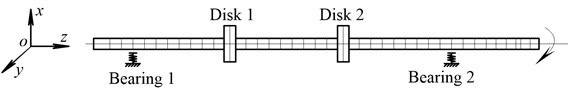
The finite element model of the local rub fault rotor system is established as shown in Fig. 1. The model is composed of 2 rigid disks, 42 finite shaft elements and 2 bearings. Values of the system parameter used for the numerical simulations are as follow: elasticity modulus, 210 GPa; shaft length, 15 mm; shaft diameter, 10 mm; disk length, 25 mm; disk diameter, 75 mm; supporting stiffness, 1×10⁶ Nm-1; supporting damping, 7×10⁴ Nsm-1; eccentric mass, 5×10⁻⁶ kg; unbalance eccentricity, 2 mm; coefficient of friction, 0.15; rub stiffness, 2×10⁵ Nm-1. The Unbalance force is at node 30. The rub fault is at node 10. The measuring points are at nodes 6, 21 and 24, respectively. Analysis is carried out in MATLAB programming.
Fig. 1Finite element model of rub rotor system
The Newmark method in conjunction with Newton-Raphson scheme (Newmark-Newton) is used to solve the nonlinear response of the system when 500 rad/s. The Newmark-Newton method is given in the Appendix A. The response curves of the measuring nodes and the rub node in the x direction are shown in Fig. 2. It can be seen that the time domain response is periodic, and the center of the vibration deviates from the equilibrium position due to the presence of the local rub fault. The response of the whole system is affected by the local rub fault.
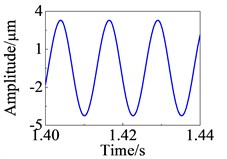
The responses of the nodes 6, 21 and the rub node are used to solve the response of the other nodes in the rotor system by the fault transfer mechanism. The response curves of the node 24 using Newmark method and the fault transfer mechanism are shown in Fig. 3. It can be seen that the two curves are perfectly coincident. It is proved that the fault transfer mechanism can be used to solve the nonlinear response of the local rub fault rotor system.
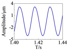
The curves of the rub force can be obtained shown in Fig. 4. It can be seen that the two curves are substantially coincident.
Fig. 2Response curve in time domain
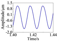
a) Node 6
b) Node 21
c) Rub node
Fig. 3Response curve in time domain at node 24
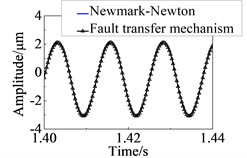
a) direction
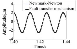
b) direction
Fig. 4Calculation results to rub force
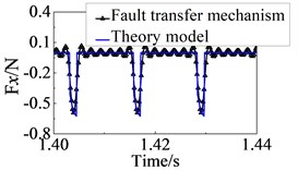
a) direction
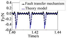
b) direction
4.2. Experimental results
Experiments are carried out by using the Bently rotor test rig and B&K3560B signal collector. Experimental equipment is shown in Fig. 5. The dynamic model of the Bently rotor test rig is the same as the numerical simulation model. The points of rub and eccentricity are at nodes 16 and 34, respectively. The sensors are placed at nodes 9, 15, 21, and 31, respectively. Measurement data are collected at rotor operating speed of 3600 n/min. The sampling frequency is 3.2 kHz.
Fig. 5Experimental equipment
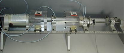
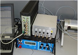
Fig. 6 shows the response curves of node 21 when the rub fault occurs. The operating state and stability of the system are judged according to the time history curve [21]. The rotor system is in a stable state. The center of the vibration deviates from the equilibrium position due to the presence of the local rub fault. 1X frequency is still dominant, 2X-6X appear in the frequency domain response.
Fig. 6Response curves at node 21
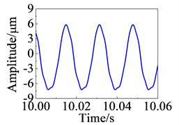
a) Time domain
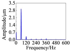
b) Frequency domain
The first six-order harmonic components are used to solve the response of node 21 by the fault transfer mechanism. Fig. 7 is the analytical results. It can be seen that the harmonic components of each order are almost coincident except 1X and 6X. The response curves obtained by measured and calculated by the proposed method also substantially coincident. The proposed method and the numerical simulations are verified from experimental investigations.
Fig. 7Comparison of experimental and theoretical results
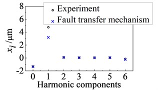
a) Harmonic components
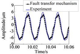
b) Response curves in time domain
5. Discussions
(1) The idea of the manuscript comes from an engineering problem. The local rub fault occurred in a compressor rotor system. The fault had been very serious when it was detected. The sensors of the monitoring system were placed on the bearing (This is a common method to place the sensors). The location of the fault was between impeller and shell, this location was far from the sensors, so the early rub fault was not detected by the monitoring system because of the distance between the location of the fault and sensors. The impeller could only be replaced when the fault was detected.
In order to improve efficiency, the clearance between stator and rotor is getting smaller and smaller. Some faults, such as rub and steam whirl, can be caused by excessive unbalance vibration. Some important locations, such as impeller and bearing, should be monitored to avoid further development of the fault.
The problem of the nonlinear response is a key scientific problem extracted from the engineering problem. To the author's knowledge, the local fault transfer mechanism is a novel method to obtain response of any other nodes. The unbalance response of the key locations is monitored when the system is operating normally, while the development of the fault can be monitored when the fault is occurred. The proposed method can solve the problem without changing the system structure.
(2) The local fault transfer mechanism is very suitable for calculating the response of some locations which is difficult to place sensor in engineering practice. It can be seen that the expression of the fault force is not required from the derivation process. So, the proposed method is applicable to other periodic fault besides rub in the rotor system.
Compared with the theoretical analysis, the expression of the fault force is not required and the response of some nodes is required, that is, it is possible to obtain the response when the expression of fault force acting on the system is unknown. Compared with the measurement method, sensor cannot be placed at some locations; the response of the locations cannot be measured and can be calculated by the proposed method.
It can be seen that the response of rotor system must be in steady state and periodic from the derivation process; the proposed method is not suitable for transient and aperiodic response. In addition, fault location is determined.
(3) The proposed method is discussed as following when the fault does not occur in the rotor system.
The equation of the rotor system of nodes without fault may be expressed:
The unbalance force and the response of the system are expanded into the form of harmonic components:
Substituting Eq. (13) into Eq. (12), the harmonic coefficients are:
The Eq. (14) is rewritten as:
Assuming that and are the th order harmonic component of response on node and , respectively. The ratio of to is:
Substituting Eq. (15) into Eq. (16), the Eq. (16) is rewritten as:
The th order harmonic component of response on node is obtained by the following:
The response on node can be expressed:
The response of any node may be obtained by Eq. (19), that is, influence of the vibration caused by unbalance on the other positions can be obtained when fault does not occur in the rotor system. Comparing with the proposed method in section 2, the method presented in this section may be called vibration transfer mechanism.
6. Conclusions
The local fault transfer mechanism in the rotor system is presented in this paper. The finite element model of the fault rotor system is established. An exciting force caused by unbalance and a local rub force are assembled to model the rotor local fault. The fault transfer mechanism is derived by the harmonic balance theory. The Newmark method is used to solve the fault rotor equations. The experimentations are carried out to measure the response of the local rub fault rotor system in the rotor test rig. The response of three nodes is used to solve the response of the other nodes by the fault transfer mechanism. The numerical simulations results show that the two curves solved by the Newmark method and the fault transfer mechanism are perfectly coincident. The proposed method and the numerical simulations are verified from experimental investigations. The vibration transfer mechanism in rotor system is discussed.
References
-
Changjiang L., Zhoulian Z., Xiaoting H., Junyi S., Weiju S., Yunping X., Jun L. L-P perturbation solution of nonlinear free vibration of prestressed orthotropic membrane in large amplitude. Mathematical Problems in Engineering, Vol. 2010, 2010, p. 1-17.
-
Xiangxi K., Xueliang Z., Qinliang L., Bangchun W. Dynamical analysis of vibratory feeder and feeding parts considering interactions by an improved increment harmonic balance method. Proceedings of the Institution of Mechanical Engineers, Part C: Journal of Mechanical Engineering Science, Vol. 229, Issue 6, 2015, p. 1029-1040.
-
Xiangxi K., Wei S., Bo W., Bangchun W. Dynamic and stability analysis of the linear guide with time-varying, piecewise-nonlinear stiffness by multi-term incremental harmonic balance method. Journal of Sound and Vibration, Vol. 346, 2015, p. 265-283.
-
Ikeda T. Bifurcation phenomena caused by multiple nonlinear vibration absorbers. Journal of Computational and Nonlinear Dynamics, Vol. 5, Issue 2, 2010, p. 21012.
-
Zhenbo L., Jiashi T., Ping C. A generalized harmonic function perturbation method for determining limit cycles and homoclinic orbits of Helmholtz-Duffing oscillator. Journal of Sound and Vibration, Vol. 332, Issue 21, 2013, p. 5508-5522.
-
Lau S. L., Cheung Y. K., Wu S. Y. Incremental harmonic balance method with multiple time scales for aperiodic vibration of nonlinear systems. Journal of Applied Mechanics, Vol. 50, Issue 4a, 1983, p. 871-876.
-
Huai X., Xianren K., Haiqin L., Zhenguo Y. Vibration analysis of nonlinear systems with the bilinear hysteretic oscillator by using incremental harmonic balance method. Communications in Nonlinear Science and Numerical Simulation, Vol. 42, 2017, p. 437-450.
-
Qian Z., Ziliang L., Yonghui H., Hongliang Y., Bangchun W. Dynamic stress prediction method for rubbing blades. Journal of Vibroengineering, Vol. 18, Issue 1, 2016, p. 1-12.
-
Hongliang Y., Chongyang W., Fan W., Bangchun W. The demension-reducetive incremental harmonic balance method for solving the response of local nonlinear dynamic system with multi-frequency exciation. Journal of Vibration Engineering, Vol. 28, Issue 5, 2015, p. 741-747.
-
Amore P., Aranda A. Improved Lindstedt-Poincaré method for the solution of nonlinear problems. Journal of Sound and Vibration, Vol. 283, Issue 3-5, 2005, p. 1115-1136.
-
Pušenjak R. R. Extended Lindstedt-Poincare method for non-stationary resonances of dynamical systems with cubic nonlinearities. Journal of Sound and Vibration, Vol. 314, Issues 1-2, 2008, p. 194-216.
-
Caiwan C., Chaokuang C. Non-linear dynamic analysis of rub-impact rotor supported by turbulent journal bearings with non-linear suspension. International Journal of Mechanical Sciences, Vol. 50, Issue 6, 2008, p. 1090-1113.
-
Woohyung K., Yeong L. J., Jintai C. Dynamic analysis for a planetary gear with time-varying pressure angles and contact ratios. Journal of Sound and Vibration, Vol. 331, Issue 4, 2012, p. 883-901.
-
Patel T. H., Darpe A. K. Vibration response of a cracked rotor in presence of rotor-stator rub. Journal of Sound and Vibration, Vol. 317, Issue 3-5, 2008, p. 841-865.
-
Junyi C., Chengbin M., Zhuangde J., Shuguang L. Nonlinear dynamic analysis of fractional order rub-impact rotor system. Communications in Nonlinear Science and Numerical Simulation, Vol. 16, Issue 3, 2011, p. 1443-1463.
-
Sung L. A., Ok K. B., Yeong-Chun K. A finite element transient response analysis method of a rotor-bearing system to base shock excitations using the state-space Newmark scheme and comparisons with experiments. Journal of Sound and Vibration, Vol. 297, Issue 3-5, 2006, p. 595-615.
-
Dakel M., Baguet S., Dufour R. Nonlinear dynamics of a support-excited flexible rotor with hydrodynamic journal bearings. Journal of Sound and Vibration, Vol. 333, Issue 10, 2014, p. 2774-2799.
-
Hongliang Y., Qingkai H., Lingxuan L., Bangchun W. Method for detecting rubbing fault in rotor system based on harmonic components. Journal of Mechanical Engineering, Vol. 48, Issue 5, 2012, p. 43-48.
-
Fulei C., Wenxiu L. Experimental observation of nonlinear vibrations in a rub-impact rotor system. Journal of Sound and Vibration, Vol. 283, Issue 3-5, 2005, p. 621-643.
-
Patel T. H., Darpe A. K. Experimental investigations on vibration response of misaligned rotors. Mechanical Systems and Signal Processing, Vol. 23, Issue 7, 2009, p. 2236-2252.
-
Qian Z., Qi X., Hongliang Y., Bangchun W. Stability of a multi-span rotor system with fluid-induced self-excited vibration. Journal of Vibration and Shock, Vol. 35, Issue 5, 2016, p. 196-200.
-
Chang T. P., Liu M. F., Chang H. C. Finite element analysis of nonlinear shell structures with uncertain material property. Thin-Walled Structures, Vol. 46, Issue 10, 2008, p. 1055-1065.
About this article

This project is supported by the National Natural Science Foundation of China (No. 51675350), the Ph.D. Startup Foundation of Liaoning Institute of Science and Technology (No. 1604B03) and the University Science Research Project of Liaoning Education Department (No. L2016lky02).
Contribution of each individual co-author are listed as follow: Zhong Wang conducts the work for simulation calculation, data results analysis and paper writing; Qi Xu completes the experimental work and the proofreading of the paper; Ziliang Liu presides over languages embellish; Hongliang Yao and Bangchun Wen grasp the macroscopic direction of the paper and offer technical guidance for programming.
