Abstract
The paper analyzes the working principle of hydraulic impactor, describes the return and stroke order of action and establishes the nonlinear mathematical model describing its dynamic characteristic. The simulation model of hydraulic impactor is established based on AMESim. The structural features of trial machine is used to constrain variables, the piston speed is assigned as the optimizing objective, and the NLPSL algorithm is used to optimize the parameters of system model of hydraulic impactor, after which the system performance is obviously improved.
1. Introduction
The hydraulic impactor is the main mechanism of hydraulic hammer and hydraulic drill machine. It is a kind of hydraulic engineering equipment which is used in the broken rock in mining and concrete building’s demolishing. [1-7]. The main structure includes hydraulic impact piston, reversing valves, anitrogen room and other basic part. In the process of the hydraulic impactor’ optimization design, the optimization of the hydraulic impactor’s performance parameters (such as impact energy and impact frequency) is the key point. Finding the relationship between performance’s parameters and structure parameters and improving the performance of the structure through optimizing the structure parameters play an important part in the research and development of hydraulic impactor. In this paper, continuous quadratic programming method (NLPQL) – the mathematical optimization method, combined with hydraulic shock AMESim simulation is used to optimize the design.
2. The working principle of hydraulic impactor
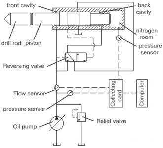
Fig. 1 shows how a hydraulic impactor works in principle. Its working process is generally divided into two stages: return and stroke, the return stage consists of return acceleration and return brake. Similarly, the stroke consists of stroke acceleration and impact pause [8-14].
Fig. 1The working principle of gas-liquid united hydraulic impactor
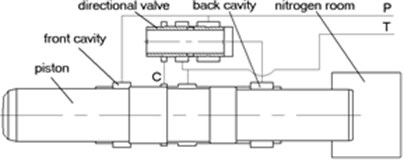
a) Return working condition
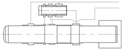
b) Stroke working condition
2.1. Return stage (return acceleration, return brake)
When high-pressure oil enters the piston front chamber, the piston back chamber is back to the tank; Under the action of the front chamber’s high-pressure oil, the piston moves up after overcoming the nitrogen’s force, fluid’s force of the back chamber, its own gravity, viscous friction, and seal’s friction resistance. which can compress nitrogen in the nitrogen chamber. The pistons make the accelerated motion in the return trip, before the high-pressure oil pass signal port C. As the piston moves to signal port C to interlink the former chamber of high pressure oil, under the action of the high-pressure oil, directional control valves commutation and switches oil circuit. Now, both front and rear chamber of the piston have high-pressure oil. Then, the piston continues to move up with the inertia effect and does return deceleration movement until it reaches the top dead center and the return trip ends.
2.2. Stroke stage (stroke acceleration, shock pause)
The position of piston and distribution flow valve areas shown in Fig. 1(b). Piston front and rear chamber both have the high-pressure oil, which constitutes a differential circuit. The former chamber’s oil enters the back chamber through the internal oil channel of distribution flow valve. Because the effective area of the rear chamber is larger than the front chamber, with the fluid pressure of piston front and rear chamber and the gas force in the Nitrogen chamber, the piston makes the accelerated stroke movement. When piston strokes to the drill rod, impact movement pauses and reversing valve changes the direction, then piston return into the initial state of next cycle. The pause time is , represents the piston length, c represents the propagation velocity of pressure wave, which generally taken 5000 m/s in steel.
3. Mathematical model of the hydraulic impactor
According to the working principle of hydraulic impact showed in Fig. 1, this research assumes a constant system pressure, incompressible and constant viscosity fluid, ignores oil quality and adiabatic nitrogen room, meanwhile all the components are rigid bodies. Based on Newton’s Second Law, fluid’s continuity principle and gas equation, we can list the following differential equations describing the hydraulic impactor’s movement:
Piston’s kinetic equation:
Dynamics equation of the spool in distribution flow valve:
Gas state equation of nitrogen room:
Flow rate‘s equilibrium equation:
On the above equation, , are the quality of the piston and the spool respectively; , , are piston’s displacement, velocity, acceleration; , , are spool displacement, velocity, acceleration; , are the angles of vertical direction to piston, spool; , is the clearance of the piston and the cylinder, the spool and valve body; , is the eccentricity of the piston, spool; , is the diameter of the pistons, the spool contacting with the cylinder; is dynamic viscosity of hydraulic oil; , are the length of the seal for the piston, spool; is the nitrogen chamber’s pressure; is the pressure difference; , , are the pressure of piston’s front, rear chamber and the valve’s front chamber; , , are the total effective areas of piston of the front chamber, rear chamber, and the nitrogen chamber; , are the bearing area of the front and rear chamber of directional control valve; is the inflation pressure of the nitrogen chamber; , are instantaneous working volume, initial volume of the nitrogen chamber; , are the initial period coefficients of pistons, spool; is leakage flow; is actually needed flow of the system.
4. Impactor system simulation model
4.1. Cylinder body model
To create the cylinder body simulation model in AMESim, we use a large set of validated libraries of pre-defined components, such as Hydraulic Component Design(HCD), Pneumatic Components Design(PCD) and so on.
4.1.1. Front cylinder body model
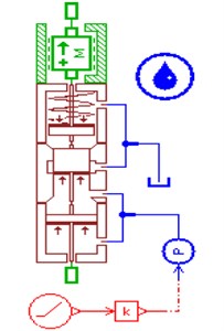
The front cylinder body of gas-liquid joint type hydraulic impactor is the nitrogen chamber, its inside is filled with the definite stressed nitrogen. We use related component model of Pneumatic Library and Pneumatic Component Design Library to create the front cylinder body simulation model, which is shown in the Fig. 2.
Fig. 2Front cylinder body model
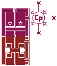
Fig. 3Middle cylinder body model
4.1.2. Middle cylinder body model
We use related component model of Mechanical Library and Hydraulic Component Design Library to create the middle cylinder body simulation model, the simulation model is based on the middle cylinder body of hollow valve core type hydraulic impactor. the model is shown in Fig. 3.
4.2. Valve type orifice system model
4.2.1. Distribution flow valve model
To analyse the dynamic characteristic of hydraulic directional valve, we use related component model of Hydraulic Component Design Library to create the two position, three-way hydraulic directional valve, the model is shown in Fig. 4.
Fig. 4Distribution flow valve model
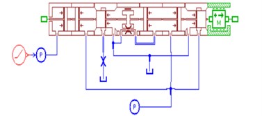
Fig. 5Relief valve model
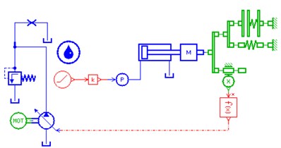
4.2.2. Relief valve model
Relief valve play a key role in overflow and safety protection, which is an indispensable element in the hydraulic system. To analyse the dynamic characteristic of hydraulic impactor system, we use related component model of Hydraulic Component Design Library to create the slide valve type direct-acting pressure relief valve, which is based on the structure and performance parameters of relief valve. The model is shown in Fig. 5.
4.3. Hydraulic power supply model
We select variable displacement hydraulic piston pump model in AMESim, and create variable regulating mechanism of hydraulic pump through hydraulic cylinder model, spring model. The simulation model of hydraulic power supply is built as Fig. 6.
Fig. 6Simulation model of hydraulic power supply
4.4. Simulation model integration of hydraulic impactor
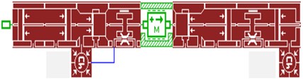
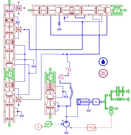
The excavator’s hydraulic system was used as the power source of impactor. This integrates the component model, selects the appropriate hydraulic lines and sets up a set of reasonable model parameters to establish the impactor’ systems simulation model. The model shown in Fig. 7 [15-17].
Fig. 7The system simulation model of hydraulic impactor
5. Parameter optimization of the hydraulic impactor
It usually uses the mathematical optimization method – Sequential Quadratic Programming (NLPQL) and is combined with the hydraulic simulation as well as computing analysis of hydraulic impactor system to optimize the critical dimension’s design of the hydraulic impactor [18].
5.1. The optimization target’s selection of impactor
The optimization goal of hydraulic impactor is to get a set of structural parameters that can make the entire hydraulic impact reach an optimal performance instead of making each subsystem achieve the optimal. Impact energy is the most important performance indicators of the hydraulic impactor, which are directly influenced by the structural parameters of impactor. This article uses the impact energy as the optimum objective.
Impact energy is calculated as follows:
In the formula, is the piston mass, is the last impacting velocity of piston.
According to the Eq. (7), the last impacting velocity of piston is the only parameter to determine the amount of the impact energy in the case that the piston’s quality has been set. Considering the limitation of material, the last impacting velocity of piston is generally not more than 12 m/s.
5.2. The optimization algorithm – NLPQL
NLPQL (Nonlinear Programming Quadratic Line search) is the realization of the sequential quadratic programming (SQP) method, which is the standard method based on the use of the gradient of the objective function and constraints to solve nonlinear optimization problems. The method is very applicable for the following conditions:
• The method is used to optimize the local problem and very suitable for local optimization;
• Function and gradient can get sufficiently high calculation accuracy;
• The problem is smooth and easy to change the scale.
As NLPQL uses the concept of the gradient, the discrete parameters can’t use this method. One of the features of this method is that the selecting optimization comes to an end once it finds a local minimum. Therefore, the obtained results largely depend on the initial value given by the algorithm. The NLPQL algorithm is very sensitive to the starting value, so it usually does not use the value on the boundary of the range of parameters as the starting value [7, 8].
NLPQL algorithm need to use AMESim to calculate the gradient of the objective function and constraints in all directions of the design space, and each input parameter is in one direction in the optimization process, AMESim uses the finite difference method to calculate the gradient value.
Assume that the objective function in which and are the two input parameters, the gradient of the function:
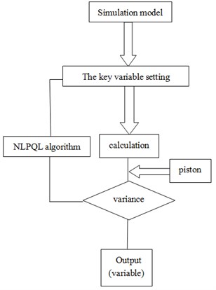
The above formula is used to calculate the gradient, is the relative gradient step size. First of all, from , , procedure works out , and then the subsequent twice run calculate respectively . The block diagram of the optimize design is shown in Fig. 8.
Fig. 8The block diagram of optimized design
5.3. Selection of design variable
According to the final shock speed of piston, the impact energy of the piston can be calculated. Theoretical analysis and experimental results show that the piston’s speed are related to system operation parameters, such as input quantity of system and initial inflation pressure of nitrogen room. Besides, it is also related to structural parameters of system, such as effective work area of former and rear cavity and the location of feedback hole of return and shock stroke and so on.
Energy consumption of reversing valve core consists of three main areas: one is the hydraulic energy losses, second is the throttling losses of valve port, and third is the leakage loss. Their size have direct relationship with effective work area of former and rear cavity of reversing valve core, and the location of reversing signal hole of valve core. When these parameters are changed, reversing speed of valve core and the quantity of hydraulic oil will be changed correspondingly.
The structural parameters of hydraulic breaking hammer system selected in the process of optimizing impact property are listed in the Table 1 in detail.
Table 1Design variables need to optimize
Name of design variable | Name in AMESim | initial value (mm) |
Piston bottom radius | R_piston_lower | 34.1 |
Piston top radius | R_piston_upper | 32.25 |
Radius of former cavity of valve core | R_valve_lower | 19.75 |
Radius of rear cavity of valve core | R_valve_upper | 19.4 |
Location of reversing signal hole of valve core of return stroke | signal_1 | 4.5 |
Location of reversing signal hole of valve core of shock stroke | signal_2 | 12.5 |
Location of piston braking signal hole | signal_3 | 54.5 |
Location of piston braking signal hole | signal_4 | 66.5 |
Note: The location of signal hole is the distance between the hole and the surface of former cavity of valve | ||
In order to make the optimization results more reliable, the actual working condition in experiment was referenced. Measured working parameters were imported into AMESim, that is to say, working pressure is 10 MPa, initial inflation pressure of nitrogen room is 0.8 MPa, return oil back-pressure is 2.3 MPa and route of piston is limited in 90 mm.
6. Design and study of structural parameters
In order to determine the effects of structural parameters on impact performance of hydraulic breaking hammer system, the following design and study of these arguments is to find which parameters have the maximum influence on the impact performance within the scope of the design respectively.
6.1. Design and study of piston parameters
Impact energy is associated with the final shock speed, which is related to stroke time and acceleration, while the stroke time is directly related to the route of piston. Besides, stroke time and acceleration are interconnected.
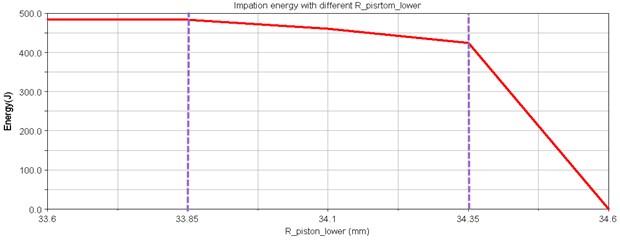
Fig. 9Impact energy curve
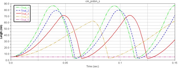
As can be seen in Fig. 9, when the piston bottom radius is changed from 33.6 mm to 34.6 mm, the impact energy of hydraulic breaking hammer remains unchanged, and then goes down. As the piston bottom radius increased to 34.35 mm, the piston impact energy and journey are reduced sharply. When the area of former cavity further reduces, as shown in the Trail 5 of Fig. 5, the piston doesn’t work normally, so the bottom design variables cannot be too large, which should be contained within 34.35 mm. When the area of former cavity of piston increases, the system can achieve higher impact energy, but we cannot blindly increase the area of operation. As shown in the Trail1 of Fig. 10, the distal radius is 33.6 mm, which is close to 90 mm (the alert value of piston stroke route), and impact energy doesn’t improve when compared with 33.85 mm distal radius.
In conclusion, through design and research comprehensively, the piston’s bottom radius should be controlled in the range of 33.85 mm to 34.35 mm.
Fig. 10Piston displacement curves
In the same way, the piston’s upper radius should be controlled from 31.125 mm to 33.25 mm. The location of braking signal hole of piston return stroke should be controlled in the range of 63.25 mm to 69.75 mm, and the location of braking signal hole of piston stroke should be controlled in the range of 54 mm to 60 mm.
Through the design and study of structural parameters of piston, the scope of each design variable was determined. Then, the sensitivity of these design variables within their scope was calculated and analyzed, the results as shown in the Figs. 11-12.
Fig. 11Design of bottom radius of piston
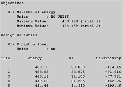
Fig. 12The location of braking signal hole of piston stroke
Judging from the analysis results, the top and distal radius of piston have higher sensitivity, and the location of braking signal hole of piston stroke and return stroke have a much lower sensitivity, but their mutual change impacts on the impact energy can’t be overlooked. So, the relation of the location of braking signal hole of piston stroke and return stroke, and the relationship between the upper and bottom radius of piston will be analyzed in experimental study of structural parameters.
6.2. Design and study of structural parameters of reversing valve core
Structural parameters of reversing valve core can also be determined by experiment initially. The working area of former cavity of reversing valve should be controlled from 19.55 mm to 19.75 mm. And the working area of rear cavity of reversing valve should be controlled in the range of 19.05 mm to 19.55 mm. When the signal hole of valve core of return stroke moves up, both the piston route and the impact’s speed increase, but the overall change is relatively small, and the influence on the impact energy is not very significant. On the contrary, the location of signal hole of valve core of shock stroke has little influence on the motion laws of piston. The impact energy can vary within a very small area, and the piston motion characteristics recorded virtually no change.
Through experiment and analysis, R_valve_lower and R_valve_upper are more sensitive than signal_1 and signal_2. Considering from design variables singly, Radii of former and rear cavity of valve core show much more influence on impact energy than the location of braking signal hole of valve core of shock and return stroke, but the influence by their interaction cannot be ignored. In the follow-up study, depending on the influence of interaction of these variables, accurate range of R_valve_lower and R_valve_upper and optimal design value of signal_1 and signal_2 can be determined, which can improve the efficiency of optimization analysis.
7. Experimental study on structural parameters
Because of only changing one variable parameter at a time, it is difficult to find a mutual influence of different design parameters on impact energy of virtual prototype of hydraulic breaking hammer. In order to find the optimal combination of design parameters, which has the best effects on impact energy, relevant experiments are designed as follows.
In order to prove the correctness of working principle about this new hydraulic impactor, we must validate the theory and principle. The experimental system of hydraulic impactor is showed in Fig. 13 and Fig. 14 [20-22].
Fig. 13The experimental system on hydraulic impactor
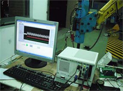
Fig. 14Experiment site
7.1. Experimental study on piston’s structural parameters
In order to obtain the impact performance of hydraulic breaking hammer under the influence of interplay of different structural parameters of valve core, two groups of experiment are carried out.
Before experiment, , the ratio of working area of former and rear cavity of piston, was defined, through which the impact performance of hydraulic breaking hammer under the influence of the value of R_piston_lower and R_piston_upper can be analyzed. Then determine the accurate value of signal_3 and signal_4, by analyzing the impact performance of hydraulic breaking hammer under the influence of them.
7.1.1. Experimental study on top and bottom radii of piston
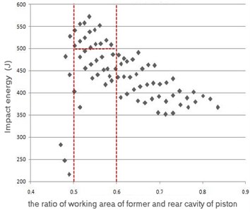
By analyzing test data of piston structural parameters, the figure can be obtained, which show the relation of impact energy and in Fig. 15. It can be seen from the figure that the values of are between 0.5 to 0.6, where impact energy is higher than 500 J. By experimental analysis, the rang of is from 0.5 to 0.6, which provides reference for the final optimization analysis.
Fig. 15Impact energy distribution
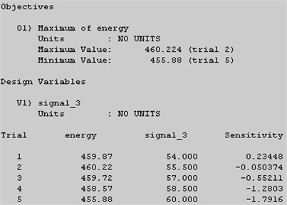
7.1.2. Experimental study on the location of braking signal hole of piston
By the previous design study and sensitivity analysis of parameters, the ranges of the distance of the two signal hole are determined. The next step is to find the optimal ratio of these two arguments, which can improve the impact energy of hydraulic breaking hammer system.
By experimental research results, the maximum and minimum impact energy and corresponding value of two arguments are shown in Table 2.
Table 2 shows that the impact energy changes in a small region with signal_3 and signal_4 changing. Moving the location of the two signal holes back appropriately, the piston route and impact energy can be improved to some extent. In short, the location of braking signal hole of piston has little influence on impact performance. For the sake of reducing computing time for subsequent optimization, the values of signal_3 and signal_4 are determined as 57 mm and 68.75 mm respectively.
Table 2Design of experiments of position of brake signal
Trial | Energy (J) | signal_3 (mm) | signal_4 (mm) | S (mm) |
Min | 400.84 | 58.50 | 64. 625 | 69.38 |
Max | 464.69 | 57 | 68.75 | 72.14 |
Original | 463.48 | 54 | 66.5 | 71.07 |
7.2. Experimental study on structural parameters of reversing valve core
In the same way, before experiment, , the ratio of working area of former and rear cavity of valve core, was defined, through which the impact performance of hydraulic breaking hammer under the influence of the value of R_valve_lower and R_valve_upper can be analyzed. The accurate values of signal_1 and signal_2 can be determined by analyzing the impact performance of hydraulic breaking hammer under the influence of them, which were listed in Table 3. By experimental analysis, the rang of is from 1.066 to 1.2, which provide reference for optimization analysis.
Table 3Impact energy range with different valve area ratio
Energy (J) | |
Energy500 | 1.075 |
470Energy 500 | 1.212 |
460Energy 470 | 1.368 |
450 Energy 460 | 1.685 |
440 Energy 450 | 1.957 |
From the research of experimental results, the maximum and minimum impact energy and corresponding value of two arguments are shown in Table 4.
Moving the location of the two signal holes up appropriately, the piston route can be increased so that the impact energy can be improved.
Table 4Design of experiments of signal port location of valve
Trial | Energy (J) | signal_2 (mm) | signal_1 (mm) | S (mm) |
Max | 500.69 | 16.50 | 8.50 | 76.50 |
Min | 411.89 | 4.50 | 0.50 | 67.30 |
Original | 463.48 | 54 | 66.5 | 71.07 |
8. Optimum design analysis of structural parameters
Through the design and experiment study of structural parameters of piston and valve core, final rang or accurate value of each parameters was determined. In order to get maximum impact energy of hydraulic breaking hammer, and the value of the individual design variables, optimum design and analysis is needed.
After final structural parameters optimization design analysis, the parameters corresponded to optimal impact energy of hydraulic breaking hammer was shown in Table 5, and the performance comparison before and after optimization was shown in Table 6.
Table 5Comparison of structural parameters before and after optimization
Name of design variable | Initial value (mm) | Optimal value (mm) |
R_piston_lower | 34.1 | 33.85 |
R_piston_upper | 32.25 | 31.25 |
R_valve_lower | 19.75 | 19.6 |
R_valve_upper | 19.4 | 19.45 |
signal_1 | 4.5 | 8.5 |
signal_2 | 12.5 | 16.5 |
signal_3 | 54.5 | 57 |
signal_4 | 66.5 | 68.75 |
Table 6Prototype performance comparison before and after optimization
Energy (J) | V (mm/s) | S (mm) | Impact frequency (bpm) | |||
Before optimization | 463.48 | 8.37 | 71.07 | 923 | 1.4017 | 0.6047 |
After optimization | 636.91 | 9.81 | 82.85 | 909 | 1.1625 | 0.5515 |
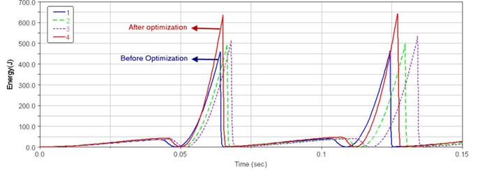
By parametric analysis of design parameters, impact energy of hydraulic breaking hammer was improved. The selected eight design parameters of piston and valve core can be divided into three categories: position of signal hole, former and rear working surfaces of valve core and former and rear working surfaces of piston, that is to say the system performance is improved after three steps’ optimization. Comparison of impact performance before and after optimization was shown in Figs. 16-18.
Fig. 16Velocity curves of the optimization process
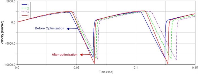
Fig. 17Displacement curves of the optimization process
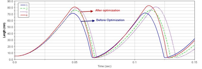
Fig. 18Impact energy curves of the optimization process
9. Conclusion
This article provides the structural parameters optimization of piston system and valve core system of virtual prototype of hydraulic breaking hammer, so that its impact energy can be improved compared to the original performance to some extent. On the basis of the initial design parameters of original model, all of the ranges of parameters were determined by design study. Then, by analyzing the parameters sensitivity, the regularity and extent of impact energy influence caused by design parameters are obtained. After parameter design research and follow-up experimental study, the efficiency of optimization analysis will be greatly improved.
Through four experiments on piston’s top and bottom radius, radius of former and rear cavity of reversing valve core,location of reversing signal hole of valve core and location of braking signal hole of piston, two bounded variables, and are constructed. By studying the influence of these two variables on the impact energy, the location of the four signal hole can be determined, which can provide the reference for optimal design.
Finally, after the optimization design analysis of structural parameters, we can find the best design values of eight structure parameters of piston and reversing valve system, and through the comparative analysis between simulation and experiment data, the system simulation model was accurate and the impact energy error between simulation and experiment was less than 20 %.
References
-
Xu Tongle, Xia Mingtang The development and research conditions on hydraulic hammer. Mechanical Engineer, Vol. 6, 2005, p. 20-21.
-
Zhou Zhihong, Gao Liwen, Xu Tongle, Zhang Kanglei, Li Jing Research on the models and selection ways to hydraulic hammer. Construction Machinery, Vol. 6, 2004, p. 66-68.
-
Zhu Falong, Yang Guoping Current research status and progress of hydraulic impactors. Mining and Processing Equipment, Vol. 41, Issue 4, 2013, p. 6-10.
-
Yang Guoping Research on design theory on the return oil chamber of a new hydraulic impactor. China Journal of Highway and Transport, Vol. 15, Issue 1, 2002, p. 113-115.
-
Yang Guoping, Liu Xiaojun, Gao Junhao, Chen Bo Design for improving hydraulic impactor based on virtual prototype technology. Machinery Design and Manufacture, Vol. 8, 2011.
-
Yang Guoping, Liu Zhong, Ding Wongsi, Yang Xiangbi Research on the precursor control valve of a new hydraulic impact hammer. Mechanical Science and Technology, Vol. 20, Issue 6, 2001, p. 836-838.
-
Yang Guoping, Gao Junhao, Chen Bo Improved design and 3D modeling of YC70 hydraulic impactor. Machinery Design and Manufacture, Vol. 5, 2011, p. 41-43.
-
He Qinghua Hydraulic Impact Mechanism Design Research. The Second Edition. Central South University Press, Changsha, China, 2009.
-
Zhou Zhihong, Liu Lianhua, et al. Advanced technology of hydraulic breaking hammer. Construction Machinery, Vol. 4, 2004, p. 39-40.
-
Wang Cong, Yang Guoping Simulation of motion characteristics for hydraulic impactor. Journal of Shanghai University of Engineering Science, Vol. 27, Issue 2, 2013, p. 124-127.
-
Chen Bo, Yang Guoping, Gao Junhao, Tian Guangdong Dynamic characteristics simulation research of hydraulic impactor based on Flowmaster. Machine Tool and Hydraulics, Vol. 39, Issue 11, 2011, p. 95-97.
-
Lin Hong, Yang Guoping, Wang Xibing, Fan Siyuan Research on return and impact travel of the hydraulic impactor. Machine Tool and Hydraulics, Vol. 36, Issue 5, 2008, p. 156-160.
-
Fang Jian, Yang Guoping, Wang Cong, Xu Xiaojian Co-simulation and test analysis of hydraulic breaking hammer based on RecurDyn and Simulink. Mining and Processing Equipment, Vol. 41, Issue 11, 2013, p. 81-86.
-
Yang Guoping, Chen Bo, Gao Jun-hao Mechanism and scheme analysis of pneumatic impactor system. Chinese Hydraulics and Pneumatics, Vol. 11, 2010, p. 5-9.
-
Chen Bo Modeling and Simulation Research of Hydraulic Impactor Based on AMESIM. Master Thesis, Shanghai University of Engineering Science, 2012.
-
Yang Guo-ping, Gao Junhao, Chen Bo Performance testing system design of hydraulic breaker based on virtual instrument. Chinese Hydraulics and Pneumatics, Vol. 3, 2012, p. 8-11.
-
Yang Guoping, Chen Bo, Gao Junhao Improved design and analysis of hydraulic impact hammer based on virtual prototype technology. Applied Mechanics and Materials, Vols. 48-49, 2011, p. 607-611.
-
Jiang Wei, Gao Qingxiu, Zhang Mingfeng, Zhang Shuzhen, Guo Haizhou, Xu Chunlong Optimization of electronic control unit pump parameters based on NLPQL. Vehicle Engine, Vol. 3, 2011, p. 25-28.
-
Yang Guoping, Chai Rui Compact energy calculation method of hydraulic hammer. Construction Machinery, Vol. 1, 2009, p. 83-85.
-
Yang Guoping, Gao Junhao, Chen Bo Performance testing system design of hydraulic breaker based on virtual instrument. Chinese Hydraulics and Pneumatics, Vol. 3, 2012, p. 8-10.
-
Ding Chongchong, Yang Guoping, Liang Cuiping, Wang Liang Research oil performance testing method for hydraulic impactor. Machine Tool and Hydraulics, Vol. 39, Issue 4, 2011, p. 56-58.
-
Wang Liang, Yang Guoping, Liang Cuiping, Ding Chongchong Test method of impact property for hydraulic breaking hammer. Construction Machinery, Vol. 8, 2009, p. 98-100.
About this article

The author wishes to thank the National Natural Science Foundation Project (50,975,169) and Shanghai University of Engineering Science Knowledge Innovation Engineering (085 Engineering) Project (JZ0901) for providing research fund and all colleagues who previously provide technical support.
Guoping Yang is responsible for task assignments and building mathematical model of the hydraulic impactor. Hanghang Wei is responsible for building simulation model of the hydraulic impactor and revising the manuscript. Huanhuan Zhang optimizes the parameters of the hydraulic impactor. Guojun Cao carries out the designand study of structural parameters. Chuanchang Li carries out the experimental study on structural parameters.
