Abstract
The isolation seismic technology has been developed during the past three decades, but it is a current focus in bridge seismic research and practice. In order to investigate the nonlinear seismic responses of isolated bridges and evaluate the effects of seismic isolation on the peak response of the bridges with lead rubber bearings (LRB) under bi-directional horizontal earthquake excitation, an analytical method of nonlinear seismic responses of continuous multi-span girder bridges with LRB and its solving method are presented considering the interaction between the restoring forces of the bearings. Shaking table test of 1/10 the scaled model of two-span girder isolated bridge with LRB have been conducted to verify effectiveness of the LRB as a seismic isolation device and peak response of isolated bridges. Experimental results well agreed with the results obtained from analytical results of peak displacement and acceleration of deck, displacement and force-displacement hysteresis loops of isolators. It is verified that analytical method given this paper is right and effective when analyzing nonlinear earthquake response of continuous girder isolated bridges with LRB. Moreover, the bi-directional coupled interaction of the restoring forces of LRB should be taken into account, which has considerable effects on the peak seismic responses of the isolated bridge.
1. Introduction
Some highway bridges that have been adopted aseismic design suffered severe damages or even collapsed during Loma Prieta earthquake (M7.0, 1989) in United States, Kobe earthquake (M7.3, 1995) in Japan and Wenchuan earthquake (M8.0, 2008) in China [1-2], which shows traditional aseismic design of bridge has its shortcomings. The bridge bearings and columns is vulnerable component of bridge structures under earthquake excitation. So the seismic performance of bridge columns and isolated bearings are investigated extensively [3-5]. Furthermore, there are other two modern seismic design approaches intended for reducing destructive effects on bridge structures caused by strong earthquakes. One is used isolation device, which is a strategy that attempts to reduce the seismic forces to near the elastic capacity of the structural member, thereby eliminating or reducing the inelastic deformations. The main concept in isolation is to reduce the fundamental frequency of structural vibration to a value lower than the predominant energy-containing frequencies of the earthquake. The other is used energy dissipation device or increased damping, which is reducing the amount of seismic energy input into the structure. In this way it is possible to limit large plastic deformations caused by the natural period enlargement. This stiffness decreases because of higher elongations due to nonlinear response, decoupling deck from pier under strong seismic events, and then increasing protection efficiency.
The lead-rubber bearing (LRB) is the well-developed seismic isolation devices for practical use in Japan and the United States [6-7]. For the present study, the LRB consisting of alternating layers of steel shims and rubber is considered as the isolation device. The LRB is very stiff in the vertical direction and flexible in the horizontal direction. The horizontal flexibility and damping characteristics of the bearing provide the desired isolation effects in the system. The horizontal flexibility transmits relatively limited earthquake forces from the piers to the superstructure. On the other hand, the damping of the bearing dissipates the seismic energy, thereby reducing the design displacement of the bridge. In addition, the inelastic deformation of the lead plug provides the hysteretic damping in the system.
There had been several studies in the past investigating the seismic design of isolated bridges with LRB. Li [8] and Pagnini and Solari [9] studied the stochastic response of a typical three-span bridge structure with the seismic isolation system consisting of rubber bearings and hysteretic dissipaters using the equivalent linearization technique. Hwang et al. [10-11] established an equivalent linear model for the seismic analysis of base-isolated bridges with lead-rubber bearings using an identification method. Ghobarah and Ali [12] and Turkington et al. [13] showed that the LRB is quite effective in reducing the seismic response of bridges. Saiidi et al. [14] studied the effectiveness of seismic isolators in reducing the force and displacement of the superstructure of a six-span bridge, and found that the use of isolators does not necessarily increase the displacement of the superstructure. Tan and Huang [15] developed an identification algorithm to investigate the dynamic properties of a base-isolated highway bridge equipped with the LRB. Zhu et al. [16] found the maximum response of isolated bridges is sensitive to the total process of earthquake ground motion. Chaudhary et al. [17] proposed the identification of system parameters from seismic accelerations recorded on a base-isolated bridge to examine the performance of various components of bridges. Jangid [18] analyzed the seismic response of isolated bridges under bidirectional earthquake excitation regarding the restoring forces of LRB as Park model.
The most previous research is conducted assuming the force deformation behavior of the LRB as bilinear with a single component of earthquake excitation. However, when the bridge system is subjected to bi-directional excitation, the assumption of unidirectional restoring force behavior of LRB may not be valid. As a result, there is a need to study the behavior of bridges isolated with LRB. An analytical model of nonlinear seismic responses of continuous multi-span isolated bridges with LRB and its solving method are carried out under bi-directional horizontal earthquake excitation considering the two horizontal orthogonal directional coupled hysteretic model of LRB in this paper. Furthermore, shaking table tests of 1/10 scaled model of continuous two-span girder isolated bridge with LRB are carried out.
2. Modeling
2.1. Isolated bridge system model
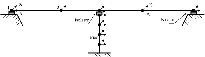
The continuous box-girder isolated bridge system representing symmetric arrangement of isolation system and substructure components are focused on for this evaluation as shown in Fig. 1. The bridge superstructure and piers are assumed to remain in the elastic state during the earthquake excitation. Abutments flexibility is assumed to be rigid and bridge piers are assumed to be rigidly fixed at the foundation level and without considering the soil structure interaction (SSI) effects. The superstructure and substructure of the bridge are modeled as a lumped mass system divided into a number of small discrete segments. Each adjacent segment is connected by a node, and at each node two degrees of freedom are considered. The masses of each segment are assumed to be distributed between the two adjacent nodes in the form of point masses. Five percent of the total mass was assumed as lumped at the substructure degree-of freedom. A damping ratio of 5 percent was assumed to account for substructure damping contributions characterized at the non-isolated frequency of the bridge system and for the total system mass. The ratio was utilized to proportion damping components acting across the substructure degree-of-freedom. According to the above assumptions, MDOF mathematical model of isolated bridge system is shown in Fig. 2, and similar bridge model is adopted using dynamic response of isolated bridge structures [6, 18].
Fig. 1Typical continuous box-girder isolated bridge system
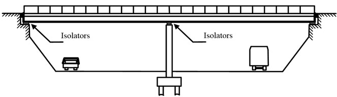
a) Elevation
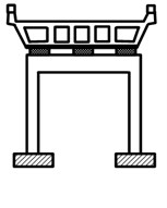
b) Section
Fig. 2Multi-degrees-of-freedom mathematical model of isolated bridge system
2.2. Mechanical modeling of isolation bearings
The uniaxial Bouc-Wen model [19-20] is widely used in random vibration analysis of modeling hysteretic inelastic system. Casciati [21] considered Bouc-Wen model as a smoothed form of the rate independent plasticity model and generalized it to the bi-directional case. The Casciati model is considered as a smoothed form of the rate-independent plasticity model. The horizontal restoring force of isolation bearings, consists of an elastic-hardening component and a hysteretic component given by:
where is the post-yield hardening stiffness, is the translational deformation and is the hysteretic force (the assumption of restoring force depends only on translational shear deformation of isolation bearings). The yield surface, is assumed to be a circular interaction surface:
where is the zero-displacement force intercept. The hysteretic can be computed from the constitutive equation:
ehere is the pre-yield elastic stiffness, is the plastic displacement increment. is governed by associative plastic flow rule:
where is the plasticity multiplier. The Kuhn-Tucker loading/unloading condition is:
The consistency condition is satisfied as:
The return-mapping algorithm for plasticity proposed by Simo and Hughes [22] is used to compute the restoring force for an isolation bearing under a given displacement history .
During a plastic regime, the rate of plastic force is:
Eq. (7) can be written as:
where is the Heaviside function, can be approximated with a smoothed function:
where , is defined as:
The rate of plastic force is approximated with:
By defining a dimensionless plastic variable , such that and uni-directional yielding displacement:
Eq. (12) becomes:
Casciati model can be rewritten in a more general form:
where , , are coefficients that control the shape of the hysteretic loop. The coefficient, and , govern the unloading force-deformation relation. The parameter governs the transition from the elastic regime to the plastic regime.
3. Equations of motion and analytical procedure
According to the MDOF mathematical model of isolated bridge system shown in Fig. 2, the equations of motion of the isolated bridge model are expressed in the following matrix form under two horizontal components of earthquake ground motion:
where , , represent the mass, damping, and stiffness matrices, respectively, of the bridge structure of order 2×2; , , represent the structural acceleration, structural velocity, and structural displacement vectors, respectively; is location matrix for the restoring force of the LRB; is vector containing the restoring force of the LRB; is the influence coefficient matrix; is the earthquake ground acceleration vector; , represent the earthquake ground acceleration in the longitudinal and transverse directions, respectively; and , is displacements of the th node of the bridge in the longitudinal and transverse directions , respectively.
The equation of motion shown in Eq. (16) was integrated numerically using Newmark’s step-by-step integration procedure. An iterative procedure is required at each time step because the assumed force-deformation relationship for the seismic isolators is nonlinear. The equations of motion in incremental form are expressed as:
where is incremental restoring force vector of the LRB.
The vector is expressed by:
where and are matrices of size 2×2 whose elements are the viscous damping and post-yield stiffness of the LRB, respectively, and is incremental pseudo-force vector containing the incremental hysteretic component of the restoring forces of the LRB. A modified Newton-Raphson procedure is used to determine the restoring force at each time step during the solution procedure. This solution procedure is implicit and unconditionally stable due to the choice of integration parameters, and . The deformation and force results can be obtained from bi-directional time-history response analysis of isolated bridge using Matlab program.
4. Outline of isolated bridge model
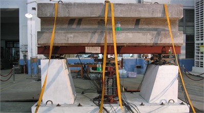
A bridge model consisting of a two-span continuous steel girder supported by LRB has been constructed for the shaking table test, as shown in Fig. 3. The bridge model is isolated by the LRB installed on the top of each pier. The substructure of bridge model consists of two rigid abutments and portal frame piers. The total span length and deck width of the prototype bridge are equal to 60 m and 9 m, respectively. The total pier height is equal to 10 m, including the cap beam.
Considering the shaking table capacity, a scaling factor of 1/10 is determined for the bridge model. Since the bridge deck is expected to exhibit rigid-body motion under horizontal excitations, the mass similarity is the major concern for the deck model. The plan dimensions of the deck model are determined to be 3 m in length and 0.9 m in width. Concrete blocks are placed on the rigid steel girder to result in a total weight of 90 kN for the deck model.
Fig. 3The 1/10 isolated bridge model
To preclude stiffness degradation due to possible concrete cracks, concrete-filled portal frame steel columns are used and designed based on stiffness similarity for the pier models. The thickness and exterior diameter of the steel pipe are determined to be 8 mm and 120 cm, respectively, from a scaled equivalent transformed section. Also, the steel cap beams are jacketed with steel plates to prevent cracks.
The LR bearings are foursquare and constructed with a 16 mm diameter central lead core, and the length of these foursquare bearings is 100 mm. The shear modulus of the elastomer used these experimental bearings is 0.8 N/mm2. The bearing is composed of 9 layers of 3 mm thick rubber and 8 layers of 1.5 mm thick steel shims with an outer (bonded) length of foursquare of 90 mm. The total rubber thickness in this bearing is 27 mm, and the first shape factor, is 8.5. The top and bottom steel end plated are 79 mm thick.
The isolated bridge model system is tested for the three real earthquake excitations. The peak acceleration and specific components of these ground motions applied in the longitudinal and transverse directions are indicated in Table 1. The test wave is obtained and used in experiment by compressing original real earthquake wave. That is to say, the compression ratio of the test wave to the original real earthquake wave is 1/3.16, and the amplitude of acceleration is modified to 0.2 g, 0.4 g and 0.6 g.
Table 1Peak ground acceleration of various earthquake ground motions
Earthquake | Recording station | Waves length (s) | Peak acceleration (g) | ||
EW | NS | UD | |||
, 1940 | Imperial | 50 | 0.214 | 0.349 | 0.211 |
, 1995 | KJMA | 50 | 0.821 | 0.599 | 0.343 |
Chi-Chi, 1999 | CHY015 | 160 | 0.145 | 0.157 | 0.032 |
5. Comparative analysis of experimental and analytical results
5.1. Deck acceleration response
The deck and bridge abutment acceleration time-history curves are shown in Fig. 4 under the PGA0.6 g bidirectional El Centro earthquake wave excitation. The reducing of deck longitudinal peak acceleration and transverse peak acceleration are 65 percent and 50 percent under longitudinal and transverse earthquake wave excited simultaneously, respectively. So seismic isolation is effective to reduce deck acceleration response, and the tendency of acceleration response of deck and bridge abutment are in-phase and same shape.
The experimental data and simulation results of the deck acceleration are shown in Fig. 5 under the PGA0.6 g El Centro wave longitudinal and transverse earthquake wave excited simultaneously. Experiment results agreed expectably with the results obtained from analytical results of acceleration of deck roughly. The difference of peak deck acceleration for analytical results is 15 percent in comparison to experimental results roughly.
Fig. 4Abutment and deck acceleration time-history curves of under the PGA = 0.6 g bidirectional El Centro earthquake wave excitation
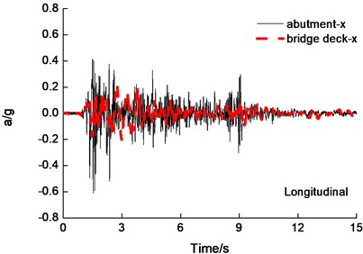
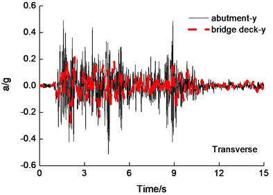
Fig. 5Deck acceleration time-history curves under the PGA = 0.6 g El Centro wave excitation
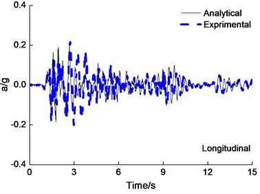
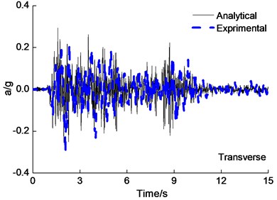
Fig. 6Deck displacement time history curve under the PGA = 0.4 g Kobe wave excitation
5.2. Deck displacement response
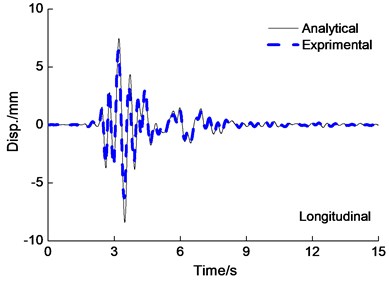
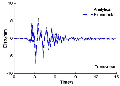
The deck displacement time-history curves are shown in Fig. 6 under the PGA0.4 g Kobe wave longitudinal and transverse earthquake wave excited simultaneously. From Fig. 6, it is also observed that experiment results agreed expectably with the results obtained from analytical results of the deck displacement. The difference of peak deck displacement for analytical results is 20 percent in comparison to experimental results roughly. Peak displacement of Cap beam and deck under multi-directional earthquake input is shown in Table 2, from Fig. 5 and Table 2, it is also observed that the deck longitudinal peak displacement under longitudinal earthquake input are smaller than under longitudinal and transverse earthquake wave input simultaneously.
Table 2Peak displacement of cap beam and deck under multi-directional earthquake input
Earthquake waves | Longitude (mm) | Horizontal and longitude (mm) | Horizontal and vertical (mm) | |||||||
-direction | -direction | -direction | -direction | -direction | ||||||
Cap-beam | Deck | Cap-beam | Deck | Cap-beam | Deck | Cap-beam | Deck | Cap-beam | Deck | |
El-Centro (0.2 g) | 1.01 | 2.98 | 0.86 | 3.56 | 0.67 | 2.86 | 0.85 | 4.61 | 0.62 | 3.21 |
El-Centro (0.4 g) | 2.84 | 8.03 | 1.54 | 6.77 | 1.09 | 6.54 | 3.01 | 8.12 | 1.02 | 6.74 |
Kobe (0.2 g) | 1.10 | 3.76 | 0.94 | 4.02 | 0.71 | 3.16 | 0.92 | 5.01 | 0.72 | 3.78 |
Kobe (0.4 g) | 3.05 | 8.94 | 1.84 | 8.47 | 1.06 | 7.13 | 3.24 | 10.2 | 1.07 | 7.97 |
Chi-Chi (0.2 g) | 2.07 | 5.78 | 2.31 | 7.91 | 1.54 | 8.34 | 2.28 | 8.65 | 2.07 | 9.22 |
Chi-Chi (0.4 g) | 5.57 | 14.61 | 3.32 | 18.4 | 3.61 | 19.10 | 3.5 | 17.89 | 3.13 | 18.86 |
5.3. Isolation bearings displacement response
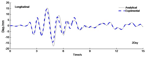
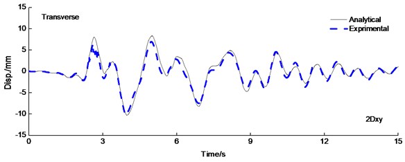
The deformation of isolated structure focused on isolated layer which absorbed and dissipated the most energy. As a result, the superstructure is protected effectively. Fig. 7 shows the displacement of isolated layer time-history curve under the PGA0.6 g Kobe wave longitudinal and transverse earthquake wave excited simultaneously. There are three similar characteristic for analytical results in comparison to experimental results. Firstly, is the peak displacement is equal and simultaneous roughly for analytical and experimental results. Secondly, the displacement response of the isolated layer is significantly influenced by the type of earthquake ground motion selected. Lastly, experiment results of isolated layer agreed expectably well with the results obtained from analytical results.
Fig. 7Displacement time history curve of LRB under the PAG = 0.6 g Kobe wave excitation
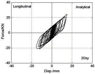
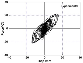
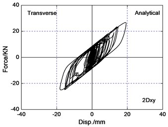
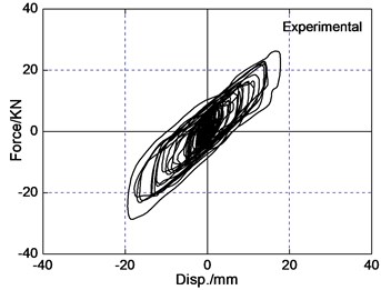
5.4. Force-deformation hysteretic behavior of LRB
The area of the hysteretic loop of the LRB implies energy dissipation capacity of isolated layer, and restoring force model depends upon the curve of the force-deformation behavior of the LRB. For the selected three pairs of recorded earthquake ground motions, it is observed that bearing restoring force curve are less irregular in bi-directional earthquake wave input than uni-directional earthquake wave input. The reason is that the interaction between the restoring forces in two orthogonal horizontal directions of LRB significantly influences the response of isolated bridges. The force-deformation behavior of LRB is plotted in Fig. 8 under the PGA0.4 g Chi-Chi earthquake wave input. The hysteretic curve loops are similar and has coupled behavior both analytical results and experimental results. The difference of peak bearing force and deformation for analytical results is 12 percent in comparison to experimental results roughly. So coupled hysteretic model of LRB used in this paper is reasonable.
Fig. 8Force-deformation loops of LRB under the PGA = 0.4 g Chi-Chi excitation
6. Conclusions
A nonlinear seismic response method of continuous girder isolated bridges with LRB is presented under bi-directional horizontal earthquake excitation considering bi-directional interaction model of LRB. The shaking table tests of continuous girder isolated bridges model with LRB under bi-directional earthquake excitation were carried out and the analytical results were contrasted to experimental results. The results can be concluded as follow:
1) Experiment results agreed well with the results obtained from analytical results of peak displacement and acceleration of model bridge deck. It is verified that computation method of seismically isolated bridge given this paper is right and effective when analyzing nonlinear earthquake response of continuous girder isolated bridges with LRB.
2) The difference of peak bearing force and deformation for analytical results is 12 percent in comparison to experimental results roughly, so bi-directional hysteretic model used in this paper of LRB is accurate and reasonable in the analysis.
3) The results show that the bidirectional interaction of the restoring forces of LRB has considerable effects on the seismic response of isolated highway bridges. There is considerable underestimation of the bearings displacements if the restoring force of LRB is idealized independently in the longitudinal and transverse directions. So bi-directional interaction of the LRB should be taken into account for the seismic isolation of bridges.
References
-
Han Q., Du X. L., Liu J. B., et al. The seismic damage of highway bridges during 2008 Wenchuan earthquake. Earthquake Engineering and Engineering Vibration, Vol. 8, Issue 2, 2009, p. 263-273.
-
Prakash S. S., Belarbi A., You Y. M. Seismic performance of circular RC columns subjected to axial, bending, and torsion with low and moderate shear. Journal of Engineering Structures, Vol. 32, Issue 1, 2010, p. 46-59.
-
Han Q., Du X. L., Zhou Y. H., et al. Experimental study of hollow rectangular bridge column performance under vertical and cyclically bilateral loads. Earthquake Engineering and Engineering Vibration, Vol. 12, Issue 9, 2013, p. 433-445.
-
Wang P. G., Han Q., Du X. L. Seismic performance of circular RC bridge columns with flexure-Torsion interaction. Soil Dynamics and Earthquake Engineering, Vol. 66, 2014, p. 13-30.
-
Deng X., Gong J., Zhou Y. Theoretical analysis and numerical simulation of variable curvature friction pendulum isolation bearing. Journal of Civil, Architectural and Environmental Engineering, Vol. 33, Issue 1, 2011, p. 50-58.
-
Priestley M. J. N., Seible F., Calvi M. Seismic Design and Retrofit of Bridges. John Wiley and Sons Inc., New York, 1996.
-
Naeim F., Kelly J. M. Design of Seismic Isolated Structures. John Wiley and Sons Inc., New York, 1999.
-
Li X. M. Optimization of the stochastic response of a bridge isolation system with hysteretic dampers. Earthquake Engineering and Structure Dynamic, Vol. 18, Issue 7, 1989, p. 951-964.
-
Pagnini L. C., Solari G. Stochastic analysis of the linear equivalent response of bridge piers with aseismic devices. Earthquake Engineering and Structure Dynamic, Vol. 28, Issue 5, 1999, p. 543-560.
-
Hwang J. S., Chiou J. M. An equivalent linear model of lead-rubber seismic isolation bearings. Engineering Structure, Vol. 18, Issue 7, 1996, p. 528-536.
-
Hwang J. S., Chiou J. M., Sheng L. H., et al. A refined model for base isolated bridges with bi-linear hysteretic bearings. Earthquake Spectra, Vol. 12, Issue 2, 1996, p. 245-273.
-
Ghobarah A., Ali H. M. Seismic performance of highway bridges. Engineering Structure, Vol. 10, Issue 3, 1998, p. 157-166.
-
Turkington D. H., Carr A. J., Cooke N., et al. Seismic design of bridges on lead-rubber bearings. Journal of Structure Engineering, Vol. 115, Issue 12, 1989, p. 3000-3016.
-
Saiidi M., Maragakis E., Griffin G. Effect of base isolation on seismic response of multi-column bridges. Structure Engineering Mechanics, Vol. 8, Issue 4, 1999, p. 411-419.
-
Tan R. Y., Huang M. C. System identification of a bridge with lead-rubber bearings. Computer and Structure, Vol. 74, Issue 3, 2000, p. 267-280.
-
Zhu D. S., Lao Y. C., Shen D. Y., et al. The seismic response features of isolated bridge with LRB. Engineering Mechanics, Vol. 18, Issue 1, 2000, p. 119-125.
-
Chaudhary M. T. A., Abe M., Fujino Y., Yoshida J. Performance evaluation of base-isolated Yama-age bridge with high damping rubber bearings using recorded seismic data. Engineering Structure, Vol. 23, Issue 8, 2001, p. 902-910.
-
Jangid P. S. Seismic response of isolated bridges. Journal of Bridge Engineering, Vol. 9, Issue 2, 2004, p. 156-165.
-
Wen Y. K. Approximate method for nonlinear random vibration. Journal of Engineering Mechanics, Vol. 101, 1975, p. 389-401.
-
Wen Y. K. Method for random vibration of hysteretic systems. Journal of Engineering Mechanics, Vol. 102, 1976, p. 249-263.
-
Casciati F. Stochastic dynamics of hysteretic media. Structure Safety, Vol. 6, 1989, p. 259-269.
-
Simo J. C., Hughes T. J. R. Interdisciplinary Applied Mathematics. Vol. 7, Computational Inelasticity. Springer-Verlag, New York, 1998.
About this article

This research is jointly funded by the National Natural Science Fund of China (Grants No. 51478022, No. 51421005), Program for Changjiang Scholars and Innovative Research Team in University (Grant No. IRT13044), and the research project of Beijing Municipal Commission of Education (Grant No. KZ201410005011). Their supports are gratefully acknowledged.
