Abstract
Four-cylinder U-shaped transmission mechanism design is closely related to operational stability, efficiency and life expectancy of Stirling engine system, as any deficiency of design of transmission mechanism may cause excessive reciprocating inertia force, centrifugal inertia force and counter-torque. Those intense forces and torques will transfer through the crankshaft bearings and the crankcase to supporting, resulting in the vibration of the Stirling engine and reducing the system operation stability and efficiency. According to features of four cylinder U-shaped drive mechanism, this paper built the counterweight theoretical model of transmission mechanism to obtain the values of counterweight and counter-balanced phase angle on crankshaft and output shaft. On this basis, dynamics simulation model of transmission mechanism can be established by multi-body dynamics simulation platform. Simulation results indicate that through certain improvement based on original design, the speed fluctuation coefficient of output shaft, left and right crankshafts is reduced by 19.2 %, 40.5 % and 37.4 % respectively; vibration displacement of the center of mass in output shaft is decreased by 19.5 %; average dynamic force and moment on engine body is diminished by 15.84 % and 20 % respectively; the weight of the flywheel can be declined by 50 % under steady working conditions. Above simulation results could verify the feasibility and effectiveness of improvement program aimed at dynamic balance. Meanwhile, this paper improves the power density of engine through the appropriate design of flywheel, striving to provide theoretical support for the design of transmission mechanism in Stirling engines.
1. Introduction
The Stiring engine is a closed cycling reciprocating piston engine by external heating (or burning). The features of Stirling engine are high efficiency, small size, light weight, compact structure, easy operation, easy maintenance, low pollution, and low noise and so on, so it can be used in many areas as clean and efficient power machine [1-3].
The Stirling engine is mainly composed of external heating system, the work of the circulatory system, transmission system, auxiliary systems, and surveillance systems. A transmission mechanism of the Stirling engine is the main component, and its function is to convert the linear reciprocating motion of the piston into a rotational movement of the output shaft of the engine power output. The crank connecting rod mechanism is the first transmission mechanism for a Stirling engine. Crank linkage can be based on the actual cylinder arrangement of flexible design, to ensure the expansion chamber and the compression chamber piston movement phase difference to meet the requirements of a certain phase angle. Crank linkage mechanism also has a simple structure, so it is still used as the main transmission mode of the Stirling engine.
Many researchers have been studying on the Stirling engine by doing experimental analysis or using numerical simulation based on theoretical model. In 1871, Schmidt proposed a simply isothermal model based on an assumption that the chambers inside the engine are of the same pressure and each chamber is fixed at a constant but distinct temperature [4]. In 1967, Finkelstein evaluated the heat transfer coefficient and the temperature variation based on a non-isothermal analysis [5]. In 1999, Makhkamov and Ingham considered the governing ordinary differential equations for the energy and mass conservation and analyzed the mechanical losses in the construction of the engine [6]. Kongtragool and Wongwises proveded a detailed literature review regarding the Stirling engines design [7].
Recently, many numerical models for the Stirling engines have been developed. In 2002, Zhang et al. presented a mathematical model of a one-stage Oxford split-Stirling cryocooler to simulate its dynamic performance, and then found the greatest deviations for the minimum pressure and net cooling power [8]. In 2009, Minassians et al. discussed the design, fabrication and experimental assessment of a symmetric three-phase free-piston Stirling engine system, and found that gas spring hysteresis loss is an important dissipation phenomenon for low-power Stirling engines during the experiment process [9]. At the same time, Benvenuto et al. presented an integrated methodology for both the design optimization and the performance evaluation of free-piston Stirling engines suitable for space applications [10]. In 2010, Alejandro et al. presented a control systems approach for the modeling and control of a kinematic wobble-yoke Stirling engine and analyzed the linear dynamics of the Stirling engine based on the dynamical model of the system [11]. In 2011 and 2014, Halit and Hamit built a the dynamic model of a free piston Stirling engine working with closed and open thermodynamic cycles and obtained a safe ranges for the hot end temperature, charge pressure, damping coefficient of the piston motion, stiffness of the piston spring and area of the displacer rod [12, 13]. In 2011, Formosa developed a coupled thermodynamic–dynamic semi-analytical model of free piston Stirling engines. This model has been validated using the experimental data available from the NASA RE-1000 Stirling engine prototype [14]. In 2012, Cheng and Yu developed a dynamic model for the beta-type Stirling engines with rhombic-drive mechanism and carried out a dynamic simulation of the engine under different operating and geometrical conditions by connecting the dynamic model to the existing thermodynamic model [15]. In 2014, Kazimierski and Wojewoda simulated a two-stroke, externally heated valve engine (EHVE) with a heater, a cooler and two blowers and found the EHVE engine reaches almost the same level of performance as the Stirling engine while using only available atmospheric air [16].
The above-mentioned studies focus on the thermodynamics analysis and control for Kinematic Wobble-Yoke Stirling Engine and free piston Stirling engines. The existing models cannot be applied for the engines with rhombic-drive mechanism and cannot be directly applied for the beta-type Stirling engines. For the four-cylinder U-transmission mechanism of Stirling engine, there are few related researches on the dynamic balance improvement design. This paper studies the four-cylinder U-transmission mechanism of Stirling engine, shown in Fig. 1. Its motion will produce reciprocating inertia force, centrifugal inertia force and counter-torque, which are periodic function of the crank rotation angle. Those force and moment pass through the crankshaft bearings and the crankcase to supporting, which results in vibration of the Stirling engine [16-18]. So designing appropriate equilibrium structure is essential to reduce the vibration of the engine and improve the reliability and life of Stirling machine running, according to analyzing the feature of U-transmission mechanism of Stirling engine. In addition, dynamics simulation model of the transmission mechanism is established by multi-body dynamics simulation platform. The simulation results could verify the feasibility and effectiveness of improvement program aimed at dynamic balance, which can provide references to the design of the transmission mechanism for Stirling engine.
2. The theoretical model of dynamic balance
The crank linkage of the four cylinder U-type structure consists of an output shaft and two crankshafts, and the crankshaft and the output shaft are connected via gears. The transmission mechanism applies to the four-cylinder double acting engine transmission, which can be extended to 8-cylinder and 12-cylinder engines. Fig. 1 shows the transmission mechanism of four-cylinder double-acting Stirling engine. As shown in Fig.1, the piston rod of No. 1 cylinder is in the upper dead point, and the crank angle is 0°. The crank phase angle of the No. 2 cylinder, No. 3 cylinder and No. 4 cylinder is 90°, 180° and 270° respectively.
In contrast with the first order reciprocating inertia force, the force is far smaller in value when its order exceeds two, and it also needs the complex structure to eliminate. Therefore, the reciprocating inertia forces with greater than second order are typically neglected [19]. At the same time, the centrifugal force generated by the rotating mass per cylinder is the same size. Because of the uniform distribution of the engine crank angle in 90°, the first order reciprocating inertia force, the second secondary reciprocating inertia force and the centrifugal force cancels itself.
Fig. 1Crank and connecting rod mechanism of four-cylinder u-shaped transmission [1]
![Crank and connecting rod mechanism of four-cylinder u-shaped transmission [1]](https://static-01.extrica.com/articles/15767/15767-img1.jpg)
Fig. 2The front view phase diagram of counterweight on the crankshaft and output shaft [1]
![The front view phase diagram of counterweight on the crankshaft and output shaft [1]](https://static-01.extrica.com/articles/15767/15767-img2.jpg)
In order to balance the first reciprocating inertia moment and the centrifugal inertia moment, the first reciprocating inertia moment is split into two halves to be balanced respectively. That is to say, the first task of balanced approach should be to balance the centrifugal inertia moment and one half of the first reciprocating inertia moment, and then to balance the remaining first reciprocating inertia moment [20]. The composition and phase of the balanced block is shown in Fig. 2. Rectangle 1, 2, 3, 4 in Fig. 3 represents respectively the each crank in cylinder; circle 0 represents the balance weight on the free end of the output shaft and the flywheel, and circle, II and III represents the counterweight on the left crank and right crank, respectively.
The counterweight on the crank balances the centrifugal inertial moment of the transmission mechanism, and then the counterweight , and will eliminate the first reciprocating inertia moment. According to the balance weight distribution and the structure of the transmission mechanism, balance weight balance equation is given by:
where is the weight of the counterweight-, is the weight of the rotary parts in each cylinder, is the weight of the reciprocating motion parts in each cylinder, is the distance between centroid of the counterweight- and the rotational center of the rotation shaft, is the axial distance between the two counterweight of output shaft, is the crank radius.
The coordinates of the rotational center for the left and right crankshaft can be obtained, according to the weight, phase, and gyration radius of the balance weight. The balance weight on the output shaft is arranged symmetrically at both ends, so the center of the rotation of output shaft is unchanged. Therefore, it is easy to obtain the weight, phase, and the radius of gyration of the counterweight on the output shaft. After the counterweight is added, the centroid coordinates of the left and right crankcase are:
where is the total weight of the counterweight on the each crank arm, (), is the weight of the original left crankcase, is the weight of the original right crankcase, is the abscissa of the left crankcase, is the ordinate of the left crankcase, is the abscissa of the right crankcase, is the ordinate of the right crankcase.
3. Dynamics simulation model
3.1. Establishment of the improved model
In order to reduce the quality of the counterweight and take full advantage of crankcase space, the center of mass of the counterweight should be away from crankshaft rotation center, which is beneficial to reduce the weight of the external combustion engine. It would be unwise to try to increase the size of the crankcase for the resettlement of the balance weight. So the gyration radius of counterweights on crankshaft are usually equal to or slightly less than crank radius, and counterweights are often designed into a fan-shaped or crescent-shaped, in order to increase the gyration radius of counterweights and reduce its weight. Meanwhile, according to the balance theory model, the weight and gyration radius of counterweight on crankshaft can be given in Table 1, and the coordinates of crankshafts in Table 2.
Fig. 3The shape, dimension and position of counterweight on the output shaft and output shaft
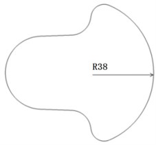
a) Original crankshaft model
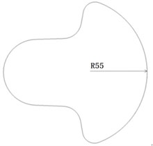
b) Improved crankshaft model
The original crankshaft model shape structure is shown in Fig. 3(a), the improved output shaft model in Fig. 3(b). According to the weight of counterweights and the centroid coordinates of crankshafts, the improved crankshaft model and output shaft model will be obtained.
Table 1The weight and gyration radius of counterweight
Counterweight | ||||
Weight (kg) | 0.567 | 0.341 | 0.497 | 0.352 |
Gyration radius (mm) | 24 | 24 | 24 | 24 |
Table 2The coordinates of each modified crankshafts
Centroid coordinate | ||
Left crankshafts (mm) | –6.478 | –6.478 |
Right crankshafts (mm) | 6.318 | 6.318 |
3.2. Equivalent model of crankshafts and sliding bearings
Each crankshaft is supported by three main journals, so this is a statically indeterminate problem, which is not directly solved by ADMAS. Therefore, the crankshaft is split into three separate parts, and these parts are connected through the dummy. The dummy and intermediate shafts are connected with each other through fixed hinge and universal hinge [21]. The fixed hinge limits all degrees of freedom; the universal hinge limits three degrees of freedom of movement and a rotational degree of freedom and retains the rotational degree of freedom around the and coordinate axis. So degree of freedom for crankshaft did not increase.
Fig. 4The equivalent dynamics simulation model of sliding bearing
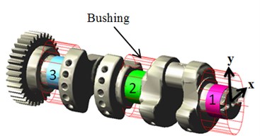
Fig. 5Change curves of the pressure of the cylinders
The model also takes into account the elastic support for the spindle neck. Bushing can provide force between the two members and play the role of the constraint member, just as the two parts are connected with the spring, which is equivalent to the sliding bearing. Therefore, the equivalent model of a thin layer oil film is built by Bushing between the shaft journal and bearing bush. Then the bearing bush and oil film are jointed with each other through revolute joint, so that it can be a more realistic simulation for the sliding bearing. As shown in Fig. 4, the crankshaft equivalent model supported by the sliding bearings is obtained in ADMAS. Table 3 shows the average stiffness and damping coefficients of the each sliding bearing [22].
Table 3The average stiffness and damping coefficients of sliding bearings
Sliding bearings | Bearing 1 | Bearing 2 | Bearing 3 | |
Stiffness | (N/m) | 3.4e8 | 5.8e8 | 4.1e8 |
(N/m) | 7.4e8 | 1.4e9 | 9.1e8 | |
Damping | (N·s/m) | 2.2e6 | 3.0e6 | 2.5e6 |
(N·s/m) | 7.5e6 | 1.2e7 | 8.8e6 | |
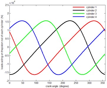
3.3. The cyclic loads of cylinders
Based on the theory of Schmidt cycle [23], pressure curves of hot chamber and cold chamber is obtained in every Stirling cycle. So it is easy to acquire the load curve of piston rod (Fig. 5), when the speed of the crankshaft is 1800 r/min. Pressure curves of each cylinder, the input load of dynamics model, are obtained by using spline functions AKISPL.
3.4. The dynamics model in ADAMS
In order to establish the dynamics model of the Stirling engine, it is necessary to simplify reasonably solid model. The improved engine solid model is also built, based on the dynamic balance theory of transmission mechanism. With the interface of ADAMS, the original and improved engine geometry model created in UG is led to ADAMS respectively. And then the boundary and constraint are added in the Table 4 under the real operating conditions [24-25].
Table 4Boundary and constraint of components
Constraint type | Body one | Body two |
Fixed | Cylinder | Ground |
Translational | Piston rod | Cylinder |
Revolute | Crosshead | Piston rod |
Revolute | Connecting rod (small head) | Crosshead |
Revolute | Crankshaft | Connecting rod (big head) |
Contact | Gear | Gear |
Translational joint motion | Piston rod | Cylinder |
4. The simulation results
It has got some parameters which have influences on the Stirling engine such as the dynamic load on engine body, the velocity fluctuations, centroid vibration of crankshafts output shaft etc. through the dynamics simulations. Here are the dynamics simulation results of original model and modified model.
Fig. 6Comparison of the speed fluctuation between original and improved model
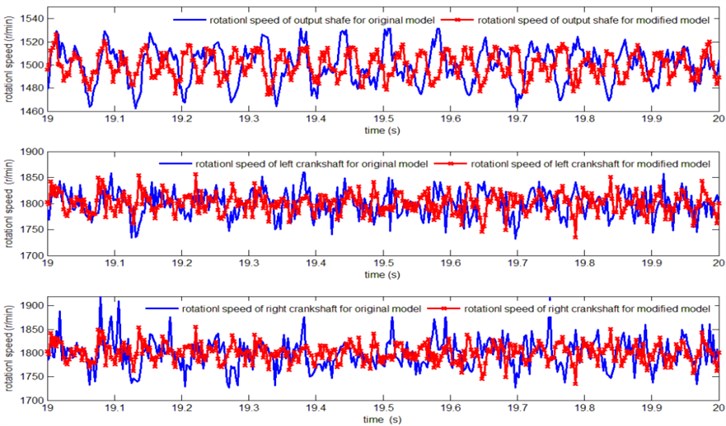
4.1. Speed fluctuations of crankshafts and the output shaft
In order to contrast the speed of the rotating shafts between the original model and the improved model clearly, it is essential to extract each shaft rotating speed variation curve in the final second, as is shown in Fig. 6. Thereby the speed fluctuation coefficients of each shaft are given in Table 5.
As the Table 5 shows, the speed fluctuation of the output shaft, the left crankshaft and the right crankshaft for the improved mode are decreased by 19.2 %, 40.5 % and 37.4 % respectively than the original model, which is beneficial to improve the transmission mechanism’s rotational stability.
Table 5Speed fluctuation coefficient of rotation shafts
Speed fluctuation coefficient | Original model | Improved model |
Output shaft | 5.2 % | 4.2 % |
Left crankshaft | 10.6 % | 6.3 % |
Right crankshaft | 13.1 % | 8.2 % |
Fig. 7The comparison of vibrations for each rotating shaft between the original model and improved model: a) Crankshaft vibration of the original model; b) Crankshaft vibrations of the improved model
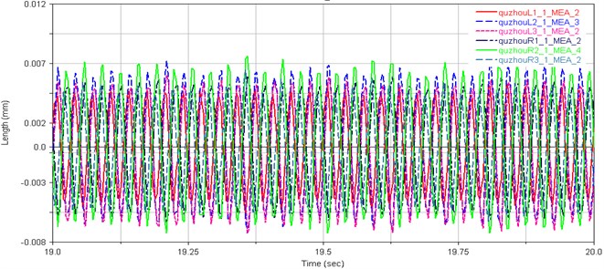
a)
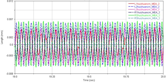
b)
4.2. Vibrations of crankshafts and the output shaft
Fig. 7(a) and (b) present the centroid vibration curves of the crankshaft for the original and improved Stirling engine model, respectively. The centroid vibration amplitudes of crankshafts and the output shaft for the original and improved Stirling engine model are given in Table 6.
As Table 6 shows, the centroid vibration amplitudes of the output shaft for the improved mode are decreased by 19.5 % than the original model, but the centroid vibration amplitudes of the crankshafts for the improved mode are increased by about 11 % than the original model. However, the centroid of vibration amplitude of the crankshaft has been increased, the vibration amplitude of the centroid of the output shaft has decreased significantly, which has improved the stability of the output shaft and output power of Stirling engine greatly.
Table 6The vibration amplitude of rotation shaft centroid
The centroid vibration amplitude (um) | Original model | Improved model | |
Output shaft | 12.15 | 9.78 | |
Left crankshaft | 5.25 | 4.9 | |
10.35 | 12.8 | ||
6.6 | 6.95 | ||
Right crankshaft | 5.25 | 4.9 | |
10.35 | 12.8 | ||
6.6 | 6.95 | ||
4.3. Loads on the engine body
Many parts and auxiliary system are fixed on the engine body which is one of the most important components in the system. The engine body sufferers many complex loads, such as gas pressure and inertia load when working. In order to compare the load on original engine body with that on modified engine model more clearly, the resultant forces on the engine body are presented in Fig. 8(a), and the total torque are presented in Fig. 8(b). The mean loads on the engine body of the original and improved Stirling engine model are given in Table 7.
Table 7The mean load on the engine body between the original model and improved model
Model | Force (N) | Moment (N·mm) |
Original model | 4829 | 3.5e6 |
Improved model | 4064 | 2.8e6 |
From Fig. 8(a) and Fig. 8(b) it can be seen that the load fluctuation of engine body reduces evidently. As Table 7 shows, the mean force and the mean moment on the engine body of the improved mode decrease respectively by 15.84 % and 20 % than the original model, which increases working stability and reliability of Stirling engine.
From the simulation results especially in Fig. 6 and Fig. 8, it can be seen that the simulation results contain the additive noise. The force and torque fluctuation is obvious. It may result from the time-varying supporting stiffness of input and output shaft and the time-varying meshing force. These fluctuation simulation results are similar to the situation in the field. The Stirling engine can not keep stable because of the extreme vibration in practical use.
Fig. 8The comparison of load on the engine body between the original model and improved model
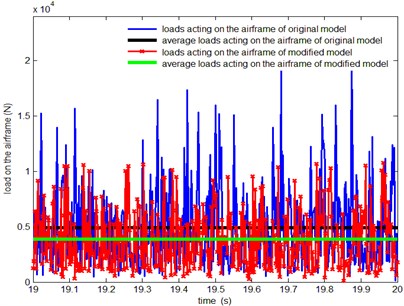
a) Resultant force on the engine
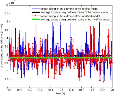
b) Resultant moment on the engine
5. Lightweight design and analysis of the flywheel
The flywheel is the key components of the four-cylinder double acting Stirling engine to ensure uniformity of operating speed, and whether the design of flywheel is appropriate will determine directly the stability and efficiency of engine. In order to reduce the layout space of transmission mechanism, increase power density and enhance the stability of engine operation, reasonable flywheel design is particularly important.
The lightweight design of the flywheel is carried out from the angel of structures and materials.
Firstly, in order to gain engine running state under the different flywheel mass and rotational inertia condition, it can be achieved by lowering the density of the original flywheel in the dynamics simulation. Based on above simulations, the appropriate flywheel mass and rotational inertia will be obtained on basis of ensuring the smooth operation of engine.
As the result of the simulations, Fig. 9 presents the effect of mass and rotational inertia the flywheel on speed fluctuation coefficient of the shafts for the dynamic model. The centroid vibration amplitudes of the shafts are given in Table 8.
Fig. 9Speed fluctuation coefficient curves of the crankshafts and output shaft
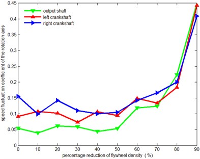
Table 8The relationship between flywheel mass and centroid vibration amplitude
Mass reduction | 0 % | 10 % | 20 % | 30 % | 40 % | 50 % | 60 % | 70 % | 80 % | 90 % |
0.330 | 0.331 | 0.331 | 0.330 | 0.331 | 0.338 | 0.337 | 0.330 | 0.334 | 0.335 | |
0.014 | 0.014 | 0.013 | 0.013 | 0.013 | 0.013 | 0.013 | 0.013 | 0.013 | 0.013 | |
0.219 | 0.219 | 0.219 | 0.219 | 0.219 | 0.221 | 0.220 | 0.218 | 0.219 | 0.221 | |
0.272 | 0.273 | 0.2721 | 0.272 | 0.272 | 0.272 | 0.273 | 0.273 | 0.272 | 0.272 | |
0.013 | 0.013 | 0.013 | 0.013 | 0.013 | 0.013 | 0.013 | 0.013 | 0.013 | 0.012 | |
0.228 | 0.113 | 0.228 | 0.228 | 0.228 | 0.228 | 0.228 | 0.227 | 0.228 | 0.229 | |
0.097 | 0.088 | 0.080 | 0.082 | 0.084 | 0.082 | 0.084 | 0.081 | 0.087 | 0.073 |
As the Fig. 9 show, the speed fluctuation coefficient of the rotation axis can be considered basically to maintain invariable as the density of flywheel reduced from 0 % to 50 %. However, when the density of flywheel reduced lower than 50 %, the speed fluctuation coefficient will increase rapidly with the density decreasing. In Table 8, the centroid vibration amplitude of the rotation axis can be basically considered to maintain invariable as the density of flywheel reduced from 0 % to 90 %. To sum up, flywheel mass and rotational inertia have no impacts on the vibration of the crankshafts and output shaft.
To summarize, in order to achieve higher power density and steady working conditions, the mass or rotational inertia of the flywheel should be decreased by 50 %.
Secondly, the mass of flywheel can be reduced by structure optimization. The first scheme reduces the mass by increasing the flywheel hole as shown in Fig. 10(a) while another scheme decreases the thickness of the flywheel as shown in Fig. 10(b). Both two lightweight structures reduce the mass by 57 % of the original one.
Table 9 shows the influence of the two lightweight structures on the system vibration.
It can be seen that increasing the flywheel hole better reduces the vibration of crankshaft and output shaft in comparison with decreasing the flywheel thickness. The maximum reduction amount reaches 29.78 % of the original one.
The relationship between different lightweight structures and rotational speed fluctuation is studied as shown in Table 10.
As Table 10 shows increasing the flywheel hole will aggravate the speed fluctuation while decreasing the flywheel thickness will cause the rotational speed fluctuation smaller. Especially for the output shaft, increasing the flywheel hole enlarges the rotational speed fluctuation by almost twice of the former one.
Fig. 10The different structure of flywheel
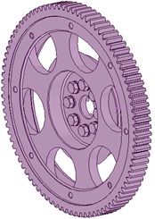
a)
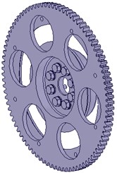
b)
Table 9The relationship between different lightweight structures and centroid vibration amplitude
(mm) | (mm) | (mm) | (mm) | (mm) | (mm) | (mm) | |
The original one | 0.3287 | 0.0135 | 0.2199 | 0.2735 | 0.0129 | 0.2295 | 0.0732 |
Decreasing the flywheel thickness | 0.3281 | 0.0125 | 0.1679 | 0.2713 | 0.0124 | 0.1827 | 0.0672 |
Increasing the flywheel hole | 0.3276 | 0.0099 | 0.166 | 0.2676 | 0.0095 | 0.1812 | 0.0514 |
Table 10The relationship between different lightweight structures and rotational speed fluctuation
Output shaft | The right crankshaft | The left crankshaft | |
The original one | 6.1 % | 11.6 % | 11.4 % |
Decreasing the flywheel thickness | 4.9 % | 9.4 % | 11.5 % |
Increasing the flywheel hole | 8.1 % | 16.2 % | 13.9 % |
6. Conclusions
According to the layout feature of the four-cylinder U-type transmission mechanism and calculating the inertial force and moment produced by the crank-rod mechanism, dynamic balance method is obtained through the equilibrium condition, which can provide a theoretical basis for dynamic balance design improvement.
Results of the Stirling engine dynamics simulation show that: some dynamic parameters of Stirling engine have been studied which have influence upon the stability of engine operation, such as speed fluctuation coefficient, the mechanical vibration, the load on the engine body etc. For the improved Stirling engine mode, the speed fluctuation coefficient of the output shaft, the left crankshaft and the right crankshaft are decreased respectively by 19.2 %, 40.5 % and 37.4 %; the centroid vibration amplitudes of the output shaft are decreased by 19.5 %; the mean force and the mean torque on the engine body are decreased respectively by 15.84 % and 20 % than the original model, which can certify the correctness and effectiveness of the dynamic balance improvement proposal.
As the result of the simulation on the different rotational inertia flywheel Stirling engine model, the mass of the flywheel is decreased by 50 % (that is to say, the rotational inertia of flywheel is decreased by 50 %), under the steady working conditions. So the total weight of Stirling engine has reduced to some extent, which is beneficial to improve power density. Increasing the flywheel hole significantly reduces the vibration condition, but will aggravate the speed fluctuation. These results provide some reference in anti-vibration design.
By simulation, the kinematics law and dynamics characteristics can be also obtained rapidly under different working conditions in order to achieve effective prediction and control about the structure and performance of the product in the early stages of the engine design, so as to provide a theoretical basis and guidance for the design and production of the Stirling engine.
The analysis model in this paper is based on a traditional and primitive four-cylinder double-crank model. More research on the new transmission models will be carried out in the next step. Moreover, the actual dynamic data will be measured based on a field test, and the analysis model can be modified in comparison with the test data.
References
-
Jin D. H. Green power – Stirling engine. World Science, Vol. 6, 1997, p. 25-27.
-
Li F., Chen H. The application of Stirling engine in energy utilization. Energy Research and Utilization, Vol. 4, 2006, p. 30-32.
-
Beale W., Wood J., Chagnot B. Stirling engine for developing countries. American Institute of Aeronautics and Astronautics, 1980, p. 1971-1975.
-
Schmidt G. Theory of Lehmann’s caloric engine. Zeit Des Vereines Deutsch Ing, Vol. 15, 1871, p. 1-12, (in German).
-
Finkelstein T. Thermodynamic analysis of Stirling engines. Journal of Spacecraft and Rockets, Vol. 4, Issue 9, 1967, p. 1184-1189.
-
Makhkamov K., Ingham D. Analysis of the working process and mechanical losses in a Stirling engine for a solar power unit. ASME Journal of Solar Energy Engineering, Vol. 121, Issue 2, 1999, p. 121-127.
-
Kongtragool B., Wongwises S. A review of solar-powered Stirling engines and low temperature differential Stirling engines. Renewable and Sustainable Energy Reviews, Vol. 7, 2003, p. 131-154.
-
Zhang C., Wu Y., Ji G., et al. Dynamic simulation of one-stage Oxford split-Stirling cryocooler and comparison with experiment. Cryogenics, Vol. 42, Issue 19, 2002, p. 577-585.
-
Minassians A., Seth R. Sanders Multiphase Stirling engines. Journal of Solar Energy Engineering, Vol. 131, Issue 11, 2009, p. 1-11.
-
Benvenuto G., De Monte F., Farina F. Dynamic behaviour prediction of free-piston Stirling engines. Proceedings of the 25th Intersociety, Energy Conversion Engineering Conference, Vol. 5, 1990, p. 346-351.
-
Alvarez Aguirre A., Garcia Canseco E., Scherpen J. Linear dynamics and control of a kinematic Wobble-Yoke Stirling engine. IEEE 49th IEEE Conference on Decision and Control, 2010, p. 2747-2752.
-
Halit K. Dynamic analysis of a free piston Stirling engine working with closed and open thermodynamic cycles. Renewable Energy, Vol. 36, Issue 6, 2011, p. 1704-1709.
-
Hamit S., Halit K. Performance comparison of a novel configuration of beta-type Stirling engines with rhombic drive engine. Energy Conversion and Management, Vol. 78, Issue 7, 2014, p. 627-633.
-
Formosa F. Coupled thermodynamic-dynamic semi-analytical model of free piston Stirling engines. Energy Conversion and Management, Vol. 52, Issue 12, 2011, p. 2098-2109.
-
Cheng C., Yu Y. Combining dynamic and thermodynamic models for dynamic simulation of a beta-type Stirling engine with rhombic-drive mechanism. Renewable Energy. Vol. 37, Issue 13, 2012, p. 161-173.
-
Kazimierski Z., Wojewoda J. Comparison of the externally heated air valve engine and the helium Stirling engine. Energy Conversion and Management, Vol. 80, Issue 6, 2014, p. 357-362.
-
Ma G., Cao Z., et al. Study on the dynamics demolition of crank-connecting rod mechanism of engine. Journal of Hebei University of Technology Vol. 33, Issue 6, 2004, p. 52-56.
-
Li B., Yang C., Liu Y. Analysis on characteristics of the movement and force of crank-connecting rod mechanism. Machinery, Vol. 33, Issue 1, 2006, p. 10-12.
-
Zhang B., Zhang L. Dynamics of Internal Combustion Engine. National Defense Industry Press, 2009, p. 140, (in Chinese).
-
Jin D. Stirling Engine Technology. Harbin Engineering University Press, 2009, p. 266, (in Chinese).
-
Hu A. Dynamics simulation analysis of diesel engine crankshaft system based on ADAMS. Coal Mine Machinery, Vol. 31, Issue 2, 2010, p. 62-65.
-
Smaili A., Khetawat M. Dynamic modeling of automotive engine crankshafts. Mechanism and Machine Theory, Vol. 29, Issue 7, 1994, p. 995-1006.
-
Yang Z. Simulation and Optimum of the Stirling Engine and the Dish-Stirling Solar Power Generation System. Beijing University of Technology, 2008.
-
Chen L., Du Y., Zhang Y., et al. Modeling and simulation of crankshaft-link-piston based on ADAMS. Journal of Mechanical Transmission, Vol. 34, Issue 7, 2010, p. 60-63.
-
Wu N., Liao R., Zhang B., et al. Multi-body system dynamics analysis of the crank and connecting rod mechanism in diesel engines. Chinese Internal Combustion Engine Engineering, Vol. 26, Issue 5, 2005, p. 69-73.
About this article

This project is supported by National Natural Science Foundation of China (Grant No. 51375001, 51309045).
