Abstract
In order to improve ride comfort and handling stability of a vehicle, this paper will present an adaptive sliding mode control algorithm for semi-active suspension systems. A hybrid reference model is proposed which combines virtues of sky-hook and ground-hook control logics, and chooses a more suitable compromise for a given application. The stability of the adaptive sliding mode control strategy is analyzed by means of Lypunov function approach taking into account the nonlinear damper characteristics and sprung mass variation of the vehicle. A state observer is designed based on unscented Kalman filter to estimate the suspension states in real-time for the realization of the controller, which improves the robustness of the control strategy and is adaptive to different types of road profiles. Finally, the performances of the controller are validated under the following two typical road profiles: the random road and half-sine speed bump road. The simulation results show that the proposed control algorithm can offer a good coordination between ride comfort and handling stability of a vehicle.
1. Introduction
Vehicle suspension system is to provide a good isolation for passengers from road disturbance and keep continuous contact between the tire and road surface. The key elements of the suspension system are spring and damper; the spring buffers the rebound motion and the damper dissipates the vibration energy. The viscous damper is a widely used shock absorber [1], which converts the vibration energy to thermal via the viscous fluid. Another type is the electromagnetic damper, and the vibration energy is converted into electrical energy via an electric motor for further use [2]. Conventional vehicle suspension, such as passive suspension, typically employs mechanical springs and dampers. The characteristics of suspension elements are generally fixed and chosen based on the design requirements of a vehicle [3]. The passive suspensions are known to have limitations to coordinate the ride comfort and handling stability. And these compromises can be solved by using active or semi-active suspensions [4]. Active suspensions can provide a good ride comfort and constrain the pitch and roll motion in transient state by acting the forces from the actuators. But the complexity, high cost and power requirements of active suspension systems limit its development and applications [5]. Semi-active suspension systems are able to enhance the suspension performance by modulating the damping force within a given range. And the semi-active suspension is more stable and fail-safe, with low energy consumption and high performances [6]. Therefore, the semi-active suspension systems have raised considerable attention and are available in a wide range of production vehicles in recent years [7-9].
A wide range of modern control theories have been applied in automotive suspension control [10-11]. The sky-hook control strategy was introduced by Karnopp et al. as a classical form for a vehicle active suspension system [12]. This control logic is simple and roust to the variation of vehicle payload. But it only dissipates energy of vehicle body mass, and the vibration of unspring mass becomes excessive. So it cannot reduce the resonant peaks of unspring mass. Some improved control algorithms are proposed to coordinate the ride comfort and handling. Hybrid sliding mode control of semi-active suspension systems was developed in Ref. [13]. Hybrid model is combined with the sky-hook and ground-hook as reference model for the sliding mode control algorithm, but in [13], road disturbance is as input for the reference model. In practice, the road disturbance information is difficult or expensive to be measured. A combination of neural networks and back-stepping control for the control of a semi-active suspension system was present in Ref. [14]. Some intelligent approaches are also applied in the suspension control since the nonlinear and uncertainty characteristics existed in vehicle suspension systems, such as neural networks [15] and genetic algorithms [16]. The mathematical proof for stability of the intelligent controller has not been demonstrated yet; and the proof of the system stability is important especially for the active suspension systems.
Sliding mode technique is a powerful method in either estimating states or controlling of a given system. Due to the simplicity and robustness, it is often applied in different systems such as suspension systems [17-18]. SMC is a nonlinear variable structure control method by application of a discontinuous signal that forces the system to slide along the restricted sliding mode surface. Chen et al. proposed a SMC for semi-active suspension [19], and this is an all-state feedback control. But some of the state information is difficult to be measured or estimated, such as tire deflection. Lam and Liao [20] proposed an SMC to track the sprung mass displacement and velocity of sky-hook reference model.
An adaptive SMC is proposed based on the designed state observer for semi-active suspension in this paper. In order to have a good coordination between the ride comfort and handling stability, a hybrid reference model is applied in the control algorithm. The suspension state estimator based on unscented Kalman filter is designed to improve the robustness of the control strategy and adaptive to different types of road disturbance. The control performance is validated in Matlab/Simulink environment under two typical road excitations. The main contributions of this paper are as follows:
a) An observer with unscented Kalman filter is designed to estimate the suspension state information in real time. The designed observer has low sensitivity to the unknown road surfaces.
b) The hybrid reference model is proposed, which could have a good coordination between the comfort and stability of the vehicle.
c) An adaptive SMC is proposed based on the state observer for semi-active suspension systems.
d) Stability of the proposed control algorithm is proved.
The remainder of this paper is organized as follows: the dynamic model of a quarter-car is presented in Section 2; the SMC algorithm is designed including the hybrid reference model and state observer in Section 3; simulation results and discussion are given in Section 4; at the end of this paper, the conclusions and future work are given.
2. Dynamic modeling
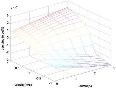
The performance of vehicle ride comfort and handling stability are heavily depending on the precision of the dynamic model of suspension. Assuming that the motion of four wheels can be decoupled and we are only interested in the frequency of vertical vibration (0-30 Hz), the quarter car suspension with 2 degree of freedom is the most commonly used model. The semi-active suspension model is shown in Fig. 1. The damping force can be adjusted by the damping continuously adjustable absorber according to the designed control algorithm. The variable damping force is achieved by controlling the flow rate and passage area of the oil inside the damper. The damping characteristic of the controllable absorber is shown in Fig. 2 according to the mathematical modeling results.
is the sprung mass of car body, including passengers, internal components and it varies according to the passenger number or payload condition of the vehicle. The absorber is continuous adjustable damper, which can be adjusted by controlling current of solenoid valve according to a given logic. is the unspring mass, which is supported by the tire modeled as liner spring with stiffness coefficient . The displacement of sprung mass and unspring mass are denoted as and respectively; and the road profile is denoted as . Assuming that there is no steering and the speed is kept constant, so we just consider the vertical motion of tire. The dynamic equations of the nonlinear suspension systems can be described as:
where, is the spring force, we assume that the spring stiffness is constant is the controllable damping force.
Fig. 1Semi-active suspension system
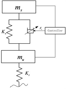
Fig. 2The velocity-current-damping force characteristics
3. Control design
3.1. Hybrid reference model
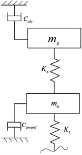
The ideal sky-hook is a comfort-oriented control policy, and the wheel motion becomes excessive since there is no damping forces applied to the unspring mass. So the vehicle handling stability will be deteriorated due to the loss of contact with the road surface. The ideal ground-hook controller is road-holding performances-oriented, but this will deteriorate the ride comfort of the vehicle. In order to improve both ride comfort and handling stability, the hybrid reference model is proposed to reduce the resonant peak values of vehicle body and wheel dynamic load. Even though neither of the two ideal controllers truly happens, we can still use this logic to design the suspension algorithm. And the hybrid reference control model is as shown in Fig. 3.
Fig. 3The configuration of hybrid reference model
The on-off sky-hook control logic can be expressed as:
where, is sky-hook reference damping coefficient.
The on-off ground-hook control logic can be expressed as:
where, is ground-hook reference damping coefficient:
where, is hybrid damping force; is the hybrid coefficient.
3.2. State estimation based on unscented Kaman filter
Some control algorithms assume that all states can be measured. But in practice, some states are difficult to be measured or not be measured at all due to the high cost or the limitation of techniques. So it is necessary to design the observer to identify the states or parameters of the system. EKF is an approximation to optimal estimation method for the nonlinear systems. It is based on the Taylor expansion theory and first order approximation to linearize the nonlinear system. But it is difficult to calculate the Jacobi matrix especially for the strong non-linear system by using the EKF estimation. The UKF is a nonlinear Kalman Filter that avoids the need for calculating the Jacobi matrix and shows superior accuracy compared to the EKF that works with a linearized model.
Choose the state vector , and the observer measurement as . Then the dynamic function can be rewritten as:
where, is the process noise, it is the derivative of road disturbance, and it is white noise with covariance ; is the observation noise which is assumed to be zero mean Gaussian white noise with covariance .
Where – vertical velocity of sprung mass; – vertical velocity of unsprung mass; – relative displacement of suspension; – tire deflection; – vertical displacement of sprung mass; – vertical displacement of unsprung mass.
And the continuous-time nonlinear system function Eq. (7) can be written as discrete-time nonlinear system function by using the first-order Taylor approximation:
where, is the sampling time.
The details of UFK theory can be referenced from [21] and [22], and it can be employed to develop a suspension state estimation approach. The UKF is a nonlinear Kalman filter that avoids the need for calculating the Jacobi matrix and shows superior accuracy compared to the extended Kalman filter based on a linearized model. The UKF is based on the Unscented Transform (UT) theory and statistical linearization technique. This technique is used to deal with the nonlinear system with a random variable through a linear regression between points drawn from the prior distribution of the random variable, named as sigma points. The detailed computation process has been presened in Table 1.
Table 1Summary of the UKF algorithm for suspension state estimation
a) The sigma vectors are propagated through the nonlinear system function: b) Measurement update: The mean of the state vector and the measurement value can be approximated by using a weighted sample of the sigma vectors: c) Covariance update The covariance of the state vectors and the measurement values can be calculated by: The weight vector can be acquired by*: d) Correction |
* considers the high order moment of the prior distribution, for Gaussian distribution, is optimal |
The sigma points are a set of points that has mean and covariance equal to the given mean and covariance. And the elements are discrete in probability distribution. This distribution can be propagated exactly by applying the nonlinear function to each point. We use the symmetrical sampling method to pick up the sigma points. For the random variable state vector , the mean is , the covariance of is denoted as . The sigma points are chosen so that their mean and covariance to be exactly as and . Let be a set of 21 sigma points (where is the dimension of the system state vector) [22]:
where, is a scaling parameter. The constant determines the spread of the sigma around the , and is usually set to a small value ; , it making sure that the covariance matrix is positive definite.
3.3. Sliding mode control
SMC is a highly robust technique for control of systems with bounded uncertainty. And it drives a state-trajectory towards a sliding surface and maintain it on the sliding surface for all the control time [23].
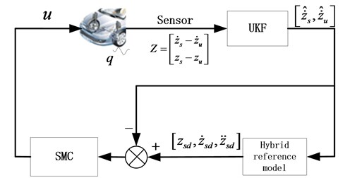
The sprung mass velocity and unspring mass velocity which are estimated by using the UKF observer are as inputs for the hybrid reference model. Since the road disturbance information is difficult to be measured or estimated specially when vehicle is moving at high speed, we use the estimated suspension state information during the reference state calculation, instead of the road input. The control diagram of SMC is shown in Fig. 4.
Fig. 4The diagram of SMC
Define the tracking error as:
where, is the desired sprung mass velocity from the hybrid reference model.
Choose the sliding surface as:
where, is the sliding surface for the heave motion; is the positive constant, here, we choose .
The derivation along surface and incorporation of system perturbation is:
where, ; is the system perturbation; is the vehicle mass perturbation.
So the equivalent control law can be deduced in absence of the system perturbation:
To consider the system uncertainties and perturbation, we consider the following sliding mode control:
where, is the continuous state feedback; is the sliding mode term representing the discontinuous state feedback control for constraining the perturbation of the system parameters and it will be designed later.
Design the following Lypunov function as following:
A sufficient condition for the stability of a sliding mode control is that the Lypunov function should subject to Eq. (17) in a neighbourhood of the sliding surface:
Substituting Eq. (15) into (17), we obtain:
We assume that, the system uncertainty boundary as , , here, we choose and . So design the nonlinear sliding mode control law as:
where, is sign function.
Substituting Eq. (15) into (18), we obtain:
where, is the Euclidean norm.
When , we have:
The original control logic by using Eq. (19) may require infinitely fast switching. This oscillation, called chattering. In real systems, a switched controller has imperfections which may lead to chatter of the system. So in order to eliminate the high frequency chattering during the switch control of SMC, an improved control law is proposed:
where, is a small positive constant.
The saturation function can be expressed as:
4. Simulation and discussion
In this section, the simulations are carried out in Matlab/Simulation environment to evaluate the performances of the adaptive SMC algorithm for the semi-active suspension. The simulations are implemented under two typical road excitations: the half-sine speed bump road and the random road. The speed bump road represents the discrete events of relatively short duration and high intensity [10]; and the smooth random road represents consistent excitations with wide range of frequencies. The parameters of the quarter car are listed in Table 2.
Table 2Parameters of off-road quarter car
Description | Symbol | Value |
Sprung mass | 2500 kg | |
Unspring mass | 250 kg | |
Spring stiffness | 166800 N/m | |
Tire stiffness | 1501200 N/m | |
Sky-hook damping coefficient | 8985 Ns/m | |
Ground-hook damping coefficient | 8985 Ns/m | |
Hybrid coefficient | 0.8 |
4.1. Case 1: Half sine speed bump road
The sine road can cause large suspension deflection in a short time. It is with the height of 101.6 mm and the length of 3.5 m according to the suggestion in reference [19], and the vehicle velocity is kept constant as 5 m/s. The UKF estimation results are shown in Figs. 5-6.
Fig. 5Sprung mass velocity estimation comparison
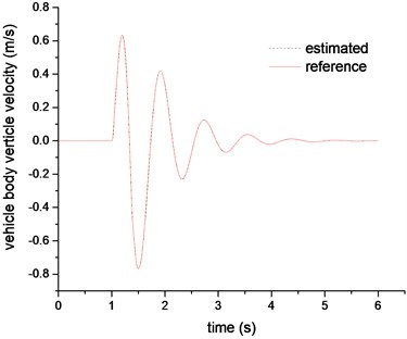
Fig. 6Unspring mass velocity estimation comparison
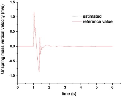
Figs. 5-6 plotted the results of estimated sprung mass velocity and unspring mass velocity, respectively. The results indicate that the proposed UKF observer can estimate the suspension sates in real time and provide accurate suspension states information for the reference model and SMC controller. The Figs. 7-9 are the control results comparison under different control laws. It can be clearly found that the SMC control can be better following the hybrid reference signals. And compared with the passive suspension system, the SMC can constrain both of the vehicle body acceleration and tire deflection. So it can be concluded that the SMC controller could achieve an excellent coordination between the ride comfort and handling stability.
Fig. 7The sprung mass acceleration comparison
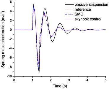
Fig. 8The suspension deflection comparison
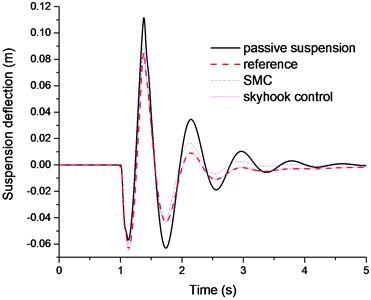
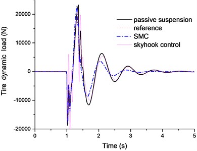
Fig. 9The tie dynamic load comparison
4.2. Case 2: Random road excitations
In this section, the rough road excitation in both time and frequency domains are studied. The ISO has proposed a series of standards of road roughness classification by using the power spectral density (PSD) values (ISO 1982). The PSD of the random road excitation can be expressed as the following form:
where, is the space frequency (m-1); is the reference space frequency, 0.01 m-1; is the road roughness coefficient; is frequency index, it reflects the frequency structure of the pavement, usually .
The random road excitation model is built by integrated Gaussian white noise. The equation of random road in time domain can be expressed as [24]:
where, is the Gauss white noise; is the low cut-off space frequency, 0.001 m-1; is the vehicle speed.
The irregular road profile is shown in Fig. 10. The vehicle speed is kept constant as 20 m/s. The simulation results are shown in Figs. 11-14.
Fig. 10The random road excitation profile
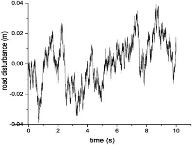
Fig. 11PSD of sprung mass acceleration comparison
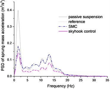
Fig. 12PSD of suspension deflection comparison
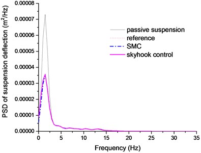
Fig. 13PSD of tire dynamic load comparison
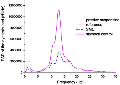
Fig. 14Time history of suspension deflection comparison
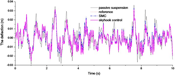
The Figs. 11-12 plotted the PSD comparison of vehicle body acceleration and suspension stroke under different control algorithms. We can find that the proposed SMC control can achieve a better control performance, even though it is not as good as the sky-hook controller. In Fig. 13, it clearly indicates that sky-hook control deteriorates tire dynamics especially in high frequency, and the SMC controller can have a good tradeoff between the ride comfort and handling stability. And this conclusion can also be drawn in Fig. 14.
5. Conclusions and future work
This paper has presented an adaptive SMC algorithm based on the hybrid reference model for semi-active suspension. The hybrid reference model combines virtues of sky-hook with ground-hook control logics and achieves a good coordination between the ride comfort and handling stability. The UKF state observer is designed to estimate the suspension states in real time based on the measurement signals from the equipped sensor in the vehicle. And the proposed SMC algorithm avoids using the road disturbance information; this will improve the robustness to the unknown road disturbances. The control performances are validated in Matlab/Simulink environment under different types of road excitations. The simulation results indicated that the proposed control algorithm can offer a good coordination between ride comfort and handling stability of the vehicle. The time delay of the actuator should be further studied in the future work.
References
-
Kashem S. B. A., Ektesabi M., Nagarajah R. Comparison between different sets of suspension parameters and introduction of new modified skyhook control strategy incorporating varying road condition. Vehicle System Dynamics, Vol. 50, Issue 7, 2012, p. 1173-1190.
-
Ren H., Chen S., Feng Z. The design and simulation analysis of electromagnetic energy regenerative suspension system. Proceedings of the FISITA 2012 World Automotive Congress, Springer, Berlin, Heidelberg, 2013, p. 601-610.
-
Liu G., Chen S. Z., Ren H. B. Matching analysis on main parameter for the shock absorber development process. Advanced Materials Research, Vol. 694, 2013, p. 393-398.
-
Chiang H., Lee L. Optimized virtual model reference control for ride and handling performance-oriented semi-active suspension systems. IEEE Transactions on Vehicular Technology, Vol. PP, Issue 99, 2014, p. 1-12.
-
Moradi M., Fekih A. Adaptive PID-sliding mode fault tolerant control approach for vehicle suspension systems subject to actuator faults. IEEE Transaction on Vehicular Technology, Vol. 63, Issue 3, 2014, p. 1041-1054.
-
Koch G., Kloiber T. Driving state adaptive control of an active vehicle suspension system. IEEE Transactions on Control Systems Technology, Vol. 22, Issue 1, 2014, p. 44-57.
-
Zong L. H., Gong X. L., Xuan S. H., et al. Semi-active H∞ control of high-speed railway vehicle suspension with magnetorheological dampers. Vehicle System Dynamics, Vol. 51, Issue 5, 2013, p. 600-626.
-
Chen H., Long C., Yuan C., et al. Non-linear modelling and control of semi-active suspensions with variable damping. Vehicle System Dynamics, Vol. 51, Issue 10, 2013, p. 1568-1587.
-
Yao Jialing, Taheri Saied, Tian Songmei, Zhang Zhongnan, et al. A novel semi-active suspension design based on decoupling skyhook control. Journal of Vibroengineering, Vol. 16, Issue 3, 2014, p. 1318-1325.
-
Cao J., Liu H., Li P., et al. State of the art in vehicle active suspension adaptive control systems based on intelligent methodologies. IEEE Transactions on Intelligent Transportation Systems, Vol. 9, Issue 3, 2008, p. 392-405.
-
Cao D., Song X., Ahmadian M. Editors’ perspectives: road vehicle suspension design, dynamics, and control. Vehicle system dynamics, Vol. 49, Issue 1-2, 2011, p. 3-28
-
Karnopp D., Crosby M. J., Harwood R. A. Vibration control using semi-active force generators. Journal of Manufacturing Science and Engineering, Vol. 96, Issue 2, 1974, p. 619-626.
-
Assadsangabi B., Eghtesad M., Daneshmand F., et al. Hybrid sliding mode control of semi-active suspension systems. Smart Materials and Structures, Vol. 18, 2009, p. 1-10.
-
Zapateiro M., Luo N., Karimi H. R., et al. Vibration control of a class of semiactive suspension system using neural network and backstepping techniques. Mechanical Systems and Signal Processing, Vol. 23, Issue 6, 2009, p. 1946-1953.
-
Guo D. L., Hu H. Y., Yi J. Q. Neural network control for a semi-active vehicle suspension with a magnetorheological damper. Journal of Vibration and Control, Vol. 10, Issue 3, 2004, p. 461-471.
-
Sun L., Cai X., Yang J. Genetic algorithm-based optimum vehicle suspension design using minimum dynamic pavement load as a design criterion. Journal of Sound and Vibration, Vol. 301, Issue 1, 2007, p. 18-27.
-
Deshpande V. S., Mohan B., Shendge P. D., et al. Disturbance observer based sliding mode control of active suspension systems. Journal of Sound and Vibration, Vol. 333, Issue 11, 2014, p. 2281-2296.
-
Balamurugan L., Jancirani J., Eltantawie M. A. Generalized magnetorheological (MR) damper model and its application in semi-active control of vehicle suspension system. International Journal of Automotive Technology, Vol. 15, Issue 3, 2014, p. 419-427.
-
Chen B. C., Shiu Y. H., Hsieh F. C. Sliding-mode control for semi-active suspension with actuator dynamics. Vehicle System Dynamics, Vol. 49, Issue 1-2, 2011, p. 277-290.
-
Lam H. F., Liao W. H. Semi-active control of automotive suspension systems with magneto-rheological dampers. International Journal of Vehicle Design, Vol. 33, Issue 1, 2003, p. 50-75.
-
Ren H., Chen S., Shim T., et al. Effective assessment of tyre–road friction coefficient using a hybrid estimator. Vehicle System Dynamics, Vol. 52, Issue 8, 2014, p. 1047-1065.
-
Julier S. J., Uhlmann J. K. Unscented filtering and nonlinear estimation. Proceedings of the IEEE, Vol. 92, Issue 3, 2004, p. 401-422.
-
Lee H., Utkin V. I. Chattering suppression methods in sliding mode control systems. Annual Reviews in Control, Vol. 31, Issue 2, 2007, p. 179-188.
-
Wu Z. C., Chen S. Z., Yang L., Zhang B. Model of road roughness in time domain based on rational function. Transaction of Beijing Institute of Technology, Vol. 29, Issue 9, 2009, p. 795-798.
About this article

The project is supported by the National Nature Science Foundation of China (Grant No. 51375046 and Grant No. 51205021).
