Abstract
Using the traditional cutting blasting technology in vertical shaft construction has some features, e.g. slows driving speed, gangue with large volume and throwing high. Moreover, large explosive charge initiation has a serious influence on freezing pipes and freezing wall. In this study, the periphery hole charge and charge structure was optimized, and the blasting model of the bedrock vertical shaft section was established by using the ANSYS/LS-DYNA numerical simulation software. In addition, stress concentration of the large diameter empty hole and its influence of blasting efficiency in blasting were analyzed. The field experiment was conducted to verify the blasting results. The results show that using large diameter empty hole blasting technology in vertical shaft construction of frozen hard rock section can significantly improve the speed of vertical shaft construction, obtain the excellent blasting effect and guarantee the safety of freezing pipes and freezing wall.
1. Introduction
Construction of vertical shaft is a key project in mine construction [1]. Engineering quantity of vertical shaft accounts for 5 % of total project amount of mine construction project. At present, in the construction process of the mine, vertical shaft cost accounts for ~20 %-30 % of total construction costs of mine. Vertical shaft project generally accounted for ~40 %-50 % of the total time limit of mine construction [2-5]. Therefore, it is important for modern mine construction to improve construction technology of shaft, improve the ability of shaft drilling equipment and accelerate the construction speed of vertical shaft.
Freezing sinking of vertical shaft which through unstable soil cover or joint development is one of the most effective construction methods in bedrock section of a large quantity of water gushing [6, 7]. When the freezing construction gets through the unstable soil cover, the drilling and blasting method will not be used in the construction. This ensures that freezing wall less entered the wild diameter in freezing. However, with the increasing in coal mining depth, a large number of shafts need through the hard sand strata. According to the geological data and experimental test, sandstone rock solid coefficient mostly is ~7-10, up to ~16, it is difficult to drill and blast, and greatly affect the tunneling speed of shaft.
In frozen hard bedrock mine vertical shaft construction, not only to improve the speed of construction, but also to ensure the safety of freeze wall and freeze pipes. Therefore, researchers in various countries are exploring. Xie et al. studied frozen soil mechanics index, such as the strength of the frozen soil, the deformation, constitutive relation, creep and stress relaxation [8]. Ling et al. reached a conclusion through experiments, the difficulty of frozen soil blasting consistent with the wave velocity from big to small order for the same kind of frozen soil, and P-wave velocity of frozen soil reflects the blastability of frozen soil significantly than the S-wave [9]. Li et al. through the frozen soil smooth blasting parameters experiment which takes frozen sand as prototype, to prove the feasibility of the implementation of the smooth blasting in frozen soil [10]. Yang et al. used numerical manifold method to carry on several simulations, the formation and development of cracks under impact loading in the process of double-hole blasting, the formation and dispersion of block, and the formation process of blasting crater, the calculation results deepen the understanding of rock failure mechanism and millisecond blasting effect [11]. Wang et al. studied the deep hole blasting, through the analysis of blast hole depth, hole concentration degree, and the relationship between blasting crater volume and the amount of explosive, pointed out that deep hole blasting can be used in vertical shaft construction of frozen hard rock section [12]. Dey et al. pointed out that cutting forms of vertical shaft deep hole blasting are parallel cylindrical cutting and inclined tapered cutting, use deep hole blasting can increase the driving speed vertical shaft [13]. Li et al. predicted the degree of compaction and optimized the distribution of blast holes by simulation model and experiment data [14]. Qu et al. carried out an experiment on inclined tapered cutting blasting, the inclined tapered cutting bottom holes are closely to each other, explosives are relatively concentrated, the rock in the circle of cutting hole can get high blasting energy, the experimental results showed that the cutting effect is exceedingly good in hard rock tunneling [15]. Li et al. conducted a simulation of large diameter empty hole spiral cutting blasting cavity forming process, and pointed out that the empty hole can provide free blasting surface to improving the blasting footage [16].
In the above study, deep hole blasting technology is the main method to improve the speed of excavation of vertical shaft, and large diameter empty hole blasting technology has never been used in frozen hard bedrock section vertical shaft construction. Recently, cutting forms of vertical shaft deep hole blasting are parallel cylindrical cutting and inclined tapered cutting. In inclined tapered cutting blasting, energy concentrated and crushing gangue throwing high. The crushing gangue often collapse sinking machinery equipment in well, moreover, drilling precision of inclined tapered cutting is not easy to control. Thus, this method is rarely applied in practice. Parallel cylindrical cutting blasting can be very well overcome the above disadvantages, and get better cutting effect. However, blasting gangue often appears in high boulder yield in deep hole blasting, bring inconvenience to the gangue cleaning.
In order to solve the above problems, in this study, large diameter empty hole blasting technology is applied in frozen hard bedrock mine vertical shaft construction, peripheral hole adopt the smooth blasting technique. The large diameter empty hole stress concentration in the course of blasting was analyzed by ANSYS/LS-DYNA, through the field experiment tests the embrasure utilization of vertical shaft freeze hard bedrock deep cutting blasting technology. This research has theoretical and practical guiding significance of vertical shaft rapid construction in frozen hard bedrock section.
2. Mathematical models
2.1. Large diameter empty holes blasting mechanism
In order to increase the cutting effect,drilling large diameter empty hole in the center of the wellbore, the empty hole can be drilled around ~40-50 m. According to the current research, beat empty hole blasting in the role of the following three aspects [16-21].
2.1.1. Stress concentration and guiding role
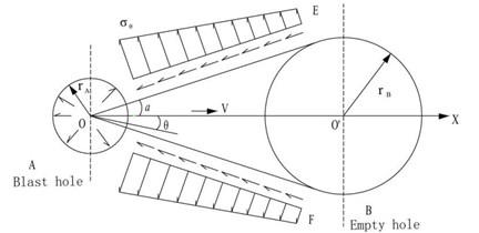
Stress waves will provoke around the borehole and spread after the explosives detonate, this high-impact action starts from the hole wall to activate the micro-cracks near the rock and make it expand. Stress wave spread to large diameter empty hole, and produce a reflection in the empty hole. Because the reflection of stress wave, the stress nearby the empty hole wall will larger than without empty holes, that shows the stress concentration effect of the empty hole. The existence of empty hole changed stress states of borehole isotropic compression generated after the adjacent detonating. The stress induced crack give priority development in the direction of a line of slot and the empty hole, the other direction of crack extension was inhibited. Meanwhile the reflection of stress wave in the wall of the empty holes enhanced stretching action in that direction. When the reflected tensile wave propagation of the explosion is near the source of crack activation zone, will guide the detonation gas directional accelerated propagation of cracks, so the existence of empty hole plays a guiding role of fracture (Fig. 1).
In Fig. 1, – additional radial explosion at a point in the rock stress, MPa; – explosion at a point in the rock shear stress, MPa; – blast hole radius, m; – empty hole radius, m; – blast hole and empty hole center distance, m; – calculation of point to line and angle hole center hole and empty hole connection.
Slots approximately coupled cylinder charges. Assuming the charge hole explosive for blasting at the same time, the blast hole A after initiation. Explosive stress wave is aroused in the surrounding rock, and the outward propagation, along with the increase of distance, the stress peak value of blast hole A according to certain attenuation law as [16, 17]:
where – the initial pressure of explosive acts on the hole wall, MPa; – the distance from the blast hole center to a point on the rock; – stress wave attenuation coefficient, , – the rock dynamic Poisson’s ratio. The Poisson’s ratio of rock is related to the strain rate and it decreases with the increase of strain rate, the relationship between the dynamic Poisson’s ratio and static Poisson’s ratio is . – dynamic lateral stress coefficient .
When the stress wave to B hole, because of the reflection of stress wave, stress near the B hole will be larger than B without empty holes, the stress performance of an empty hole concentration effect. Based on the theory of elastic mechanics, the peak of B near the hole stress state is expressed as [16, 17]:
where, – radial empty hole stress concentration stress in rock, MPa; – shear stress concentration in the air to rock stress, MPa; – empty shear stress concentration after rock stress, MPa; – distance from the empty hole center to a point in the rock, m.
When , , , the boundary conditions are taken into Eq. (4):
can be obtained from Eq. (7) and , when :
By the analysis of stress concentration effect theory, maximum tensile stress occurs in the empty hole wall in connection with slot, and with the increase of empty hole diameter, more significant role in guiding, the groove cavity of the broken rock zone is bigger.
2.1.2. Free surface effect
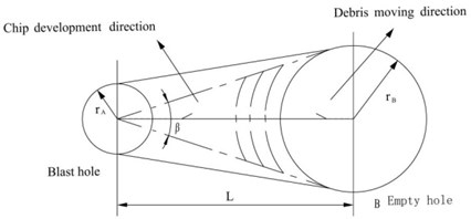
The purpose of straight slot is to provide a free surface for the caving blasting of follow-up delayed detonation. The existence of empty hole provides free surface for the blasting cutting. As shown in Fig. 2, according to the basic principle of fluid mechanics, in the straight hole blasting with empty hole, blast hole explosion makes the rock medium between blast hole and empty hole broken, and first of all to empty hole direction, with the help of empty hole free surface, corresponding to the empty hole wall produces the impact of the rebound and forming the tensile stress waves, due to the low dynamic tensile strength of rock, causes the rock began to flake off from the empty hole wall to charge hole direction, forming a groove cavity. When the empty hole diameter increases, strengthening the empty hole reflection, the reflected tensile wave scope also increases, which is more conducive to the rock.
Fig. 1Stress concentration effect analysis diagram of the empty hole
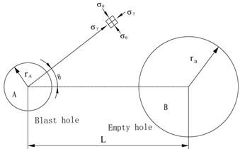
Fig. 2Free surface effect analysis diagram of the empty hole
In the straight hole blasting, the throwing direction of rock broken approximately vertical to the empty hole wall. The formation of broken cutting mainly to the impact of shear, when the per meter hole charge is certain, optimal spacing of is a function of the empty hole diameter, can be approximated solving by numerical.
According to the Newton iterative method, combined with each meter blast hole’s charge calculation formula of cutting charge holes, we obtain the following function [18, 19]:
where , – per meter hole charge, kg/m; – blast hole radius, m; – empty hole radius, m; – charge density, kg/m3; – charge detonation velocity, m/s; – blasting of rock density, kg/m3; – blast hole and empty hole center distance, m; – the initial velocity of rock throwing, m/s; – average speed of crack propagation in rock mass explosion, m/s; [] – the shear strength of rock, N/m2; – charging coefficient, cut hole is calculated based on ~0.6-0.8. Eq. (10) is derived from Eq. (9):
where . Newton iterative formula is:
The absolute value of the difference of two adjacent shall meet the conditions: .
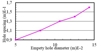
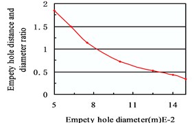
For shale, 3×10⁷ N/m2, 2700 kg/m3, the 2nd explosives, 1000 kg/m3, 3600 m/s; other parameters 0.7, (medicine column radius) 0.014 m, 0.016 m. The relationship between hole spacing and diameter of empty hole was obtained by using BASIC program (Fig. 2).
Fig. 3Relationship between hole spacing and diameter of empty hole
a)
b)
Fig. 3(a) shows, the optimal hole spacing with the empty hole diameter increased, but from Fig. 3(b) shows the optimal hole spacing and the empty hole diameter ratio was decreased with the increase of empty hole diameter.
Containing parallel hole cut blasting hole layout way is varied. The calculation model is used only for the calculation of relevant parameters of empty hole distance nearest blast hole. Other charges can determine the optimal resistance according to the actual blasting free surface width. By a similar method, free surface width and the optimal resistance are given by [16, 18]:
where – optimal resistance, m; – free surface width (vertical with throwing direction), m. Other symbols are the same as the symbols in Eq. (9).
2.1.3. Shear failure theory
As shown in Fig. 4, the blast hole blasting, rock particle radial displacement occurs under the action of the compression stress wave, is the speed. For the rock medium of well lane working face, except for OE and OF belong to the infinite body, within OE and OF belong to limited medium body, charge a fixed value resistance, thus the two ranges, particle suffered different resistance in the process of moving, the moving speed is not the same. This has resulted in the mobile OE and OF face internal and external side of rocky point exists a velocity gradient, inevitably produces shear stress on OE and OF surfaces. In addition, due to the pressure side effects, rock radial compression, tensile stress will exist in the tangential direction, so OE and OF face not only the existence of shear stress at the same time also there is tension stress.
The rock is fragile body, the tensile and shear capacity is relatively small, thus the role of these two kinds of stress, OE and OF surface generate tensile shear failure, the formation of cracks, rock within OEFO and original rock separated, and threw the empty holes by the detonation gas expansion driven force. The projectile along the OE and OF surface damage is shear failure or tensile fracture, mainly depends on the empty hole diameter (free surface width) and the empty hole and the relative ratio of charge hole center. When considering the cut blasting, the clamping effect of rock is relatively large, that realization of cutting mainly to overcome the shear strength of OE and OF surface, and make the projectile has a certain cast speed.
Fig. 4Analysis of shear failure
2.2. Security of freezing pipe safety measures
In a deep hole blasting of vertical shaft frozen soil, the effect of blasting to freezing pipes safety is related to the explosive stress wave velocity transfer in the rock and rock properties. For sandstone, detonation wave propagation velocity shows a growth trend by the rock wall to outside, in the peak and then attenuation, and gradually stabilized, close to the original stress zone. Because of the influence of blasting, the rock loose circle around the wellbore formation, according to the freezing construction experience, freeze pipes located outside the rock loose circle, will not occur to broken pipes incidents for blasting.
Freezing pipes from the surrounding the eye is very close, so the charge controls of periphery holes and an explosive of ignition and adopt reasonable delay time is the main measures to ensure the safety of the freezing pipes.
2.2.1. Periphery hole charge calculation and charge structure
The empirical formula of the control of periphery holes explosive charge is [22]:
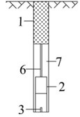
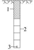
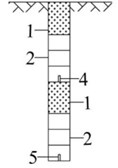
where – periphery hole maximum charge, kg; – peripheral hole distance, m; – peripheral hole in freezing distance, m. When the distance between freezing pipe and hole wall is less than 1.2 m, the above formula available periphery hole charge; equal to and greater than 1.2 m, can according to the light explosion requirements calculate the peripheralwhole charge. In order to achieve a cutgood blasting effect and ensure the safety of freezing pipes wall, charge structure using radial coupling with longitudinal air interval charge, peripheral holes use 35 mm water gel explosive charge, no coupling coefficient 1.43, longitudinal have a certain length of air gap longitudinal have a certain length of the air gap. The hole bottom blasting was used in all gun ports (Fig. 5).
Fig. 5Charge structure diagram: a) peripheral hole with air interval charge structure; b) two order cut hole and auxiliary hole using continuous loading; c) first-order cut hole with section charge structure. 1 – plugging materials; 2 – cartrige; 3 – detonator; 4 – first detonator; 5 – second detonator; 6 – crabstick; 7 – air layer
a)
b)
c)
2.2.2. Millisecond blasting shock absorption
According to the observation data, the continuation time of a blasting vibration is generally ~4-8 ms, but we design primer detonator used the 100 ms extension, so shock superposed may not happened caused by different segments of detonator. Therefore, we can put the periphery hole initiation as an independent initiation process. In the reasonable selection of blasting parameter at the same time, we should also strengthen cooperation on construction and frozen, stop brine circulation every time before blasting, to check and correct after blasting and then resume normal operation.
3. Numerical simulations
In order to improve the ability of rock breaking comparison of large diameter empty hole in the stage parallel hole cut blasting effect. Comparison of numerical simulation is adopted in this research cut blasting with large diameter empty hole and the empty hole, cutting hole divided into the first step groove eye and the second. The groove eyes in the same order are in the same initiation time. The delay time of the second step groove eye is 2000 us. To facilitate the observation of the empty hole near the stress and crack, this study establishes 1/2 model and uses the model to generate complete conditions [23, 24].
3.1. Model establishment
In the 3D model of shaft blasting, the type of model element is SOLID164 element. The simulation model (800 cm×400 cm×600 cm) is built according to the size of the wellbore. The length of the charge is 450 cm, the stemming length is 150 cm, cutting hole diameter is 50 mm, empty hole diameter is 100 mm, cartrige diameter is 40 mm, cutting hole spacing is 240 cm. In the model, the number of rock elements is 408450, the number of explosive material elements is 72396, the number of tamping plug material elements is 53604, the number of air material elements is 53867, the number of nodes is 514552.
The reflectionles boundary condition was applied in the upside, rear and two sides of models applied. To simulate the clamping effect of rock in the shaft, the fixed constraint was applied at the rear and two sides. The underside is the plane of symmetry, and symmetrical constraint was imposed on the nodes of the surface.
According to the actual size of the model, establishes the cutting blasting model in ANSYS10.0. Defining the properties for each kind material before the elementary division (Mainly is the simple definition, the real material property need to generate the K file right after the change in the K file). And then on explosives, stemming, air of refinement, the rock controlling element size reasonable on the surface element uses the surface size controller unit in the grid control. Finally, the sweep element division of rock mass V-sweep was used to ensure the unit is hexahedral element.
In order to describe the rock rheology on the action of the explosion impact plastic hardening softening, the elastoplastic constitutive equation was used to describe the rock in this study.
The material model is related to the strain rate, so the strain can be considered to failure. To select the isotropic or kinematic hardening, hardening parameter can be adjusted between 0 (only the kinematic hardening) and 1 (only the isotropic hardening). The Cowper-Symonds model is used to establish the strain rate, with the relevant factor and strain rate that yield stress, which can be expressed as Eq. (14):
where – initial yielding stress; – hardening parameter; – rate of strain; and are the strain rate parameters of the Cowper Symonds model; – effective plastic strain; – plastic hardening modulus was obtained from Eq. (15):
where and are elasticity modulus and tangent modulus, respectively.
The parameters in Eqs. (14)-(15) can generally be selected from Table 1 [25-29].
In LS-DYNA explosive materials are described by the blasting explosive material equation and state equation. While modeling is not explosive materials and equation of state, in the formation of the K file after the change in the K file.
The type of material for explosives is (*MAT-HIGH-EXPLOSIVE-BURN), and the general JWL High Explosive equation is:
The parameters in the formula can generally be selected from Table 2 [26-29].
Air material using (*MAT_NULL), there are two types of LS-DYNA equation of state to describe the air material. The equation of state (EOSLINEAR-POLYNOMIAL) can be expressed as Eq. (17):
The parameters in the formula can generally be selected from Table 3 [26].
Table 1Rock mechanics parameters
Density (g∙cm-3) | Hardening exponent | Modulus of elasticity (GPa) | Poisson’s ratio | Compressive strength (MPa) | Tensile strength (MPa) | Failure strain |
2.63 | 0.5 | 28 | 0.20 | 170 | 13 | 0.6 |
Table 2Explosive parameters selection
(kg/m3) | (m/s) | (GPa) | (GPa) | |||||
1250 | 3900 | 4.20 | 0.45 | 3.55 | 0.16 | 0.45 | 3.15 | 1.0 |
Table 3Air material parameters
(kg/m3) | (MPa) | (MPa) | (J/m3) | ||||||
1.25 | 0.1 | 0 | 0 | 0 | 0.4 | 0.4 | 0 | 2.5×10⁵ | 1.75×10⁻⁵ |
Tamping plug material using (*MAT_PLASTIC), and the mechanical parameters are: density is 1670 kg/m3, elastic modulus is 2 GPa, Poisson’s ratio is 0.22.
Lagrange and ALE are two different methods provided by LS-DYNA 3D for simulation of the explosion, these two methods are adopted to simulate the relationship between explosive and blasting structure. In Lagrange, element connection of explosives and structure can be established through sharing node. In ALE, explosive is defined as fluid, it could avoid the adverse effects of mesh distortion on calculation results in the explosion process. Decoupling charge is adopted in the research, Lagrange algorithm is adopted in rock and stemming, while the Euler algorithm is adopted in explosive and air, the grid coupling of explosive, air and surrounding rock through command definition, thus numerical simulation of the explosion process is realized by ALE algorithm.
3.2. Results
The built in ANSYS model is derived from the K file. In accordance with the provisions of table K files modified material parameters. The K file into the LS970 solver to solve. The calculation of the structure of the d3plot file after the introduction of LS-PREPOST1.0 processing software for processing analysis. The symmetric model will be mirrored into a complete structure model using reflect operation with the key Misc. (Fig. 6).
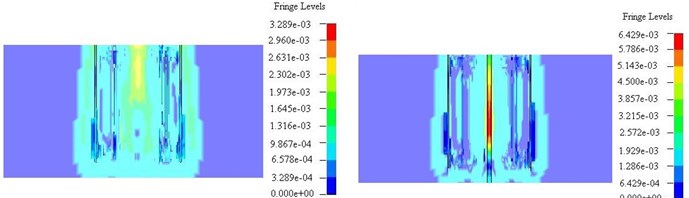
Fig. 6Stress state comparison chart of perpendicular to the direction of blasting hole (left – non empty cutting hole, right – empty cutting hole)
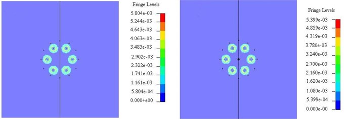
a) 100 us
b) 120 us
c) 280 us
d) 400 us
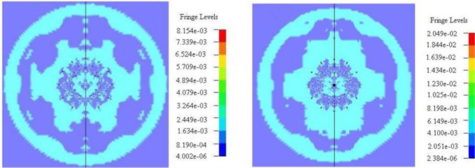
e) 2100 us
f) 2200 us
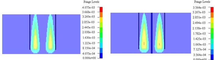
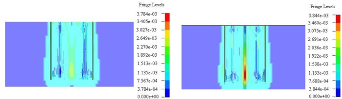
In order to clearly observe the stress concentration near the empty hole, the cross section perpendicular to the free surface map was used for analysis (Fig. 7).
4. Field experiment
The reconstruction project of Hengyuan coal mine is 9 km in width from east to west, 7 km in width from north to south, and the area is about 46.09 km2. The project is located in the northwest of Liuqiao Town, Suixi County, Huaibei City, which is 8 km away from Huaibei city in the east, is neighbored Henan province in the west, connects shallow mine boundary between No. 1 Mine of Liuqiao and Hengyuan coal mine in the south and is closed to limited boundary of exploration right in the north. The project constructs two shafts, one is the air shaft and the other one is the return air. The designed net diameter of return air shaft is 7.6 m and full depth is 993.5 m. Freezing sinking is constructed for design topsoil and freezing bedrock, the bottom boundary freezing bedrock depth is 273.5 m, freezing depth is 315 m and freezing segment supporting depth is 307 m. The Permian bedrock Shiqianfeng freezing zone can be found when the checking holes through the Cenozoic loose layer group, generally freezing depth is about 22.70 m. According to the exploration data, there is a fault judged as F17 normal faults, tendency is the north east and north west, inclination is 70°, drop is 30-70 m, extended over 4.6 km long northwest side about 50 m away from the wellbore department. In addition, the fault is reliable fault of drill hole and three-dimensional seismic tomography control.
According to the measured data, the deep wells smooth blasting test section is mainly sandstone lithology when driving north, and sandstone rock solid coefficient is 12 to 18, dense and hard. According to theory, combined with on-site construction conditions and rock properties, the hard rock of the north freezing segment performed well blasting parameters are designed (Fig. 8 and Table 4 (a-b)).
The combined effect of blasting statistics is shown in Table 5. The rock crushing circumstances surrounding the eye side and the eye marks after blasting are shown in Fig. 9(a) and (b), respectively.
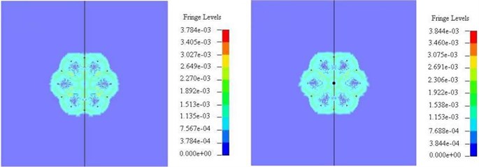
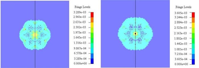
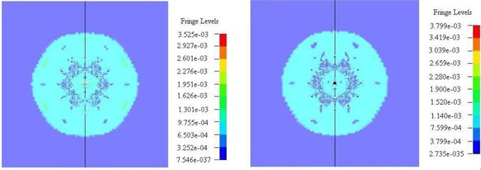
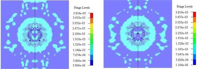
Fig. 7Stress state comparison chart of parallel to the direction of blasting hole (left – non empty cutting hole, right – empty cutting hole)
a) 120 us
b) 200 us
c) 240 us
Table 4aBlasting parameter table
Circle No. | Blast hole | Hole No. | Pre-circle Blast-hole number | Blast hole angle (º) | Blast hole depth (m) | Blast hole location | |
Hole space (mm) | Circle diameter (mm) | ||||||
1 | Cutting hole 1 | 1-6 | 6 | 90 | 5.30 | 850 | 1700 |
2 | Cutting hole 2 | 7-18 | 12 | 90 | 5.30 | 650 | 2500 |
3 | Brukup borehole 1 | 19-38 | 20 | 90 | 5.00 | 710 | 4500 |
4 | Brukup borehole 2 | 39-68 | 30 | 90 | 5.00 | 680 | 6500 |
5 | Periphery hole | 69-115 | 47 | 87 | 5.00 | 510 | 7600 |
Table 4bBlasting parameter table
Circle No. | Explosive charge | Detonator order | Connection mode | |||
Single hole | Circle hole | |||||
Cartridge number | Weight (kg) | Cartridge number | Weight (kg) | |||
1 | 7 | 5.60 | 36 | 28.80 | 1 | Bundle coupling |
2 | 6 | 4.80 | 60 | 48.00 | 5 | |
3 | 8 | 4.00 | 140 | 70.00 | 7 | |
4 | 7 | 3.50 | 180 | 90.00 | 9 | |
5 | 4 | 2.00 | 141 | 70.50 | 11 | |
Total | 307.30 | |||||
Fig. 8Blasting hole arrangement diagram
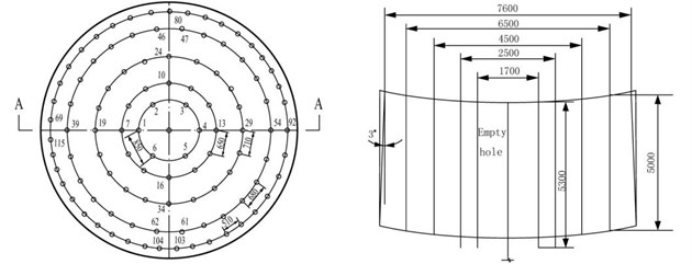
Table 5Blasting effect comparison
Project name | Unit | Non empty hole | Empty hole ( = 100 mm) |
Excavated section area | m2 | 54.10 | 54.10 |
Properties of rock | f | 12-18 | 12-18 |
Blast hole depth | m | 5.20 | 5.20 |
Efficiency of borehole | % | 89.20 | 93.80 |
Cyclical footage | m | 4.64 | 4.88 |
Circulating blasting off rock volume | m3 | 216.12 | 218.20 |
Fig. 9Field experimental results
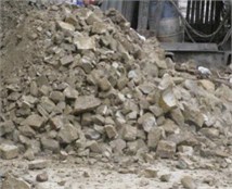
a) Broken rock
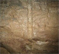
b) Periphery hole residual pore
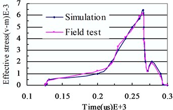
Fig. 10Empty hole effective stress comparison
5. Discussion
The first order borehole explosion generated strong shock wave, which was outward diffusion in concentric way. Simultaneously, shock wave energy decayed also very fast, the scope of the shock wave is ~10-15 times of the hole diameter. Stress wave of the adjacent blast hole began to overlay when 120 us (Fig. 6(b)). It can be seen from Fig. 6(c) that the cut way non empty holes in a 280 us middle circle the stress on the free surface appear concentration, this is because of the six cutting hole stress superposition, the maximum stress is ~230-263 MPa. The empty hole cut in 280 us near the free surface empty holes appear stress concentration, and the maximum stress is ~252-288 MPa. After 400 us, the first step groove eye stress superposition, and then forms concentric circles stress wave transfer outward. Fig. 6(e)-(f) is the transfer process of stress wave caused by the second step groove eye. In the second step groove eye, the blast hole shock wave attenuation, then hole stress waves are superimposed on each other. Finally concentric circles stress wave was formed and transferred outward.
It can be seen from Fig. 7 (a-c), after the detonation of the first step groove eye, a fusiform stress area near blasting hole was formed, this is because of the reverse initiation of explosives from down successive initiation. About 200 us, stress wave reaches the center court. If there is a non empty hole in the circle, each hole stress superposition formation stress concentration. And the maximum stress concentration is about 260 MPa, if the blasting process contains a large empty hole, stress concentration near the hole formed in the air at the time of 240 us, the maximum concentration of stress is about 640 MPa.
According to the above simulation analysis, it can be found that when the large diameter empty hole was used, the first step groove eye initiation can produce in the empty hole near the stress concentration phenomenon, blasting will appear after a circle of reflection crack produced by the effect of the reflected tensile wave in the air near the hole. Therefore, the large diameter empty hole in shaft in deep hole blasting can improve blasting quality, and reduces the gangue block rate.
It can be seen from Table 5, during the entire driving cycle test section and for the no empty hole, the average cycle footage is 4.64 m, the borehole average utilization rate is 89.20 %. While the large-diameter empty hole of footage is 4.88 m, the borehole average utilization rate is 93.80 %. This shows that the use of a large diameter empty hole cut blasting deep borehole utilization was significantly higher than a non-empty hole blasting method which can significantly improve the speed of shaft construction.
From the Fig. 9, full face in rock crushing and blasting block are uniform, bulk rate is very low, which will help grab rock machine rock, and protects the freezing shaft pipes effectively, such as freeze-fracture security incidents when blast around the eye surface neat, during the trial, indicating that the large diameter hollow bore hole blasting technique for the freezing hard rocks is feasible.
Trials of non-empty bore holes and empty hole with a drilling 25 m, the aperture of 100 mm, were carried out and cycled six times. The field test of an empty hole concentration stress contrast to the situation is shown in Fig. 10.
According to Fig. 10, it can be found that the effective stress of the simulation empty hole coincides with the curve of field tests within 300 microseconds. According to field trials, the maximum concentration stress of empty hole is up to 600 MPa, similar to the results of the simulation. This shows that use the set of large diameter empty hole in the hole cut blasting, you can get a good cut blasting effect.
6. Conclusion
Large diameter empty hole blasting has some characteristics, e.g. stress concentration and stress guidance, provide free surface is cut blasting and reflected tension shock wave breaks rock. In this research, the results of ANSYS/LS-DYNA numerical simulation software and field engineering experiment indicated that the maximum stress near large diameter empty hole is more than 600 MPa. However, if without large diameter empty hole the mutual superposition maximum stress near the center circle is just about 300 MPa. In freezing hard bedrock section vertical shaft construction, using large diameter empty hole blasting technology, the average drilling depth is 5.20 m, the average cycle drilling length is 4.88 m and blast-hole utilization rate reached 93.80 %, the bulk rate decreased. Thus, this technology can improve the driving speed of frozen hard bedrock mine vertical shaft construction greatly. In peripheral holes, smooth blasting technology and air decking were adopted for avoiding over-break and under-break. Meanwhile, multi-deck blasting technology was used to reduce single-section amount of blasting cartridges to guarantee the safety of freezing pipes and freezing wall. Therefore, this research has important theoretical significance and application value for kilometer deep vertical shaft rapid excavation and lining construction safety in frozen hard bedrock section.
References
-
Wang Y., Zhang C., Xue L., Huang X. Prediction and safety analysis of additional vertical stress within a shaft wall in an extra-thick alluvium. Mining Science and Technology, Vol. 20, 2010, p. 350-356.
-
Wang L., Cheng Y.-P., Ge C.-G., Chen J.-X., Li W., Zhou H.-X., et al. Safety technologies for the excavation of coal and gas outburst-prone coal seams in deep shafts. International Journal of Rock Mechanics and Mining Sciences, Vol. 57, 2013, p. 24-33.
-
Tao H., Weihao Y., Zhijiang Y., Chi Z., Dongliang B. Monitoring study of shaft lining concrete strain in freezing water-bearing soft rock during mine shaft construction period in west China. Procedia Engineering, Vol. 26, 2011, p. 992-1000.
-
Özkan İ., Erdem B., Ceylanoğlu A. Characterization of jointed rock masses for geotechnical classifications utilized in mine shaft stability analyses. International Journal of Rock Mechanics and Mining Sciences, Vol. 73, 2015, p. 28-41.
-
Lee J., You K., Jeong S., Kim J. Proposed point bearing load transfer function in jointed rock-socketed drilled shafts. Soils and Foundations, Vol. 53, 2013, p. 596-606.
-
Zhang J. X., Zhang X. Z., Guo X. Z., Jiang J. X., Wu L. J. Water in rush analysis and manage measures of shaft sinking by freezing method. Disaster Advances, Vol. 5, 2012, p. 452-456.
-
Duda R. Methods of determining rock mass freezing depth for shaft sinking in difficult hydrogeological and geotechnical conditions. Archives of Mining Sciences, Vol. 59, 2014, p. 517-528.
-
Xie Q., Zhu Z., Kang G. Dynamic stress-strain behavior of frozen soil: experiments and modeling. Cold Regions Science and Technology, Vols. 106-107, 2014, p. 153-160.
-
Ling X., Li Q., Wang L., Zhang F., An L., Xu P. Stiffness and damping radio evolution of frozen clays under long-term low-level repeated cyclic loading: experimental evidence and evolution model. Cold Regions Science and Technology, Vol. 86, 2013, p. 45-54.
-
Li H. B., Lv Y. X., Liu Y. Q., Qiao W. G., Chen S. H., Yan Y. F., et al. Influencing factor analysis of interference vibration reduction of millisecond blasting. Disaster Advances, Vol. 5, 2012, p. 494-501.
-
Renshu Y., Yanbing W., Huajun X., Maoyuan W. Dynamic behavior analysis of perforated crack propagation in two-hole blasting. Procedia Earth and Planetary Science, Vol. 5, 2012, p. 254-261.
-
Wang F., Tu S., Yuan Y., Feng Y., Chen F., Tu H. Deep-hole pre-split blasting mechanism and its application for controlled roof caving in shallow depth seams. International Journal of Rock Mechanics and Mining Sciences, Vol. 64, 2013, p. 112-121.
-
Dey K., Murthy V. M. S. R. Prediction of blast-induced overbreak from uncontrolled burn-cut blasting in tunnels driven through medium rock class. Tunnelling and Underground Space Technology, Vol. 28, 2012, p. 49-56.
-
Li Q. W., Li Yuan, Dasgupta G. , Song D. P., Qiao L., Wang L. P., Dong J. H. Analysis of the Blasting Compaction on Gravel Soil, Journal of Chemistry, (in Press).
-
Qu S., Zheng X., Fan L., Wang Y. Numerical simulation of parallel hole cut blasting with uncharged holes. Journal of University of Science and Technology Beijing, Mineral, Metallurgy, Material, Vol. 15, 2008, p. 209-214.
-
Li P., Wang Y. J., Ke B. Numerical simulation for cavity formation process by progressive large diameter empty hole spiral cut blasting. 2nd ISRM International Young Scholars’ Symposium on Rock Mechanics: Achievements and Ambitions, Beijing, China, 2011, p. 803-807.
-
Yang Q., Wang H., Wang J. Blasting control techniques for an urban hard-rock tunnel passing under brick-wood buildings. Modern Tunnelling Technology, Vol. 51, 2014, p. 199-202.
-
Yang G.-L., Jiang L.-L., Yang R.-S. Investigation of cut blasting with duplex wedge deep holes. Journal of China University of Mining and Technology, Vol. 42, 2013, p. 755-760.
-
Konicek P., Soucek K., Stas L., Singh R. Long-hole destress blasting for rockburst control during deep underground coal mining. International Journal of Rock Mechanics and Mining Sciences, Vol. 61, 2013, p. 141-153.
-
Yang R.-S., Che Y.-L., Tong X., Mi Y.-L., Feng L. Experimental study on the technology of middle empty hole in parallel hole cut blasting. Global Conference on Civil, Structural and Environmental Engineering and the 3rd International Symposium on Multi-field Coupling Theory of Rock and Soil Media and Its Applications, Yichang, China, 2012, p. 1314-1317.
-
Yang G., Yang R., Huo C., Che Y. Numerical simulation of stress wave propagation induced by cut blasting in multi-media. 3rd International Conference on Applied Mechanics and Mechanical Engineering, ICAMME, Macau, China, 2012, p. 22-25.
-
Wu L., Yu D., Duan W., Zhong D. Rock failure mechanism of air-decked smooth blasting under soft interlayer. International Conference on Chemical, Material and Metallurgical Engineering, ICCMME, Beihai, China, 2011, p. 617-621.
-
Wu K.-C., Li B., Tsai K.-C. The effects of explosive mass ratio on residual compressive capacity of contact blast damaged composite columns. Journal of Constructional Steel Research, Vol. 67, 2011, p. 602-612.
-
Thiagarajan G., Kadambi A. V., Robert S., Johnson C. F. Experimental and finite element analysis of doubly reinforced concrete slabs subjected to blast loads. International Journal of Impact Engineering, Vol. 75, 2015, p. 162-173.
-
Qiao L., Li Q. W., Dasgupta G., Ma S. W., Wang L. P., Dong J. H. Blasting vibration safety criterion analysis with equivalent elastic boundary: based on accurate loading model. Shock and Vibration, (in Press).
-
Wang F. T., Tu S. H., Yuan Y., Feng Y. F., Chen F., Tu H. S. Deep-hole pre-split blasting mechanism and its application for controlled roof caving in shallow depth seams. International Journal of Rock Mechanics and Mining Sciences, Vol. 64, 2013, p. 112-121.
-
Fakhimi A., Lanaria M. DEM-SPH simulation of rock blasting. Computers and Geotechnics, Vol. 55, 2014, p. 158-164.
-
Yan J. H., Lu W. B., Zhao Z. G., Yan P., Chen M. Safety distance for secondary shotcrete subjected to blasting vibration in Jinping-II deep-buried tunnels. Tunnelling and Underground Space Technology, Vol. 64, 2013, p. 112-121.
-
Menezesa P. L., Lovell M. R., Avdeev I. V., Higgs C. F. Studies on the formation of discontinuous rock fragments during cutting operation. International Journal of Rock Mechanics and Mining Sciences, Vol. 71, 2014, p. 131-142.
About this article

This research was founded by the National Natural Science Foundation of China (No. 51374012, No. 51174004) and Anhui Province Science and Technology Project (No. 1501041123).
