Abstract
The electromechanical integrated magnetic gear (EIMG), in which the field modulated magnetic gear, drive and control are integrated, is proposed in this paper. The dynamic model of the EIMG system with four subsystems is founded and the model assumptions are given. Then, the electromagnetic coupling stiffnesses are calculated by the finite element method and the dynamic differential equations are deduced. On the basis of the modal analyses of the EIMG system, the changes of the natural frequencies with the system parameters are discussed. The results show that the electromagnetic coupling sitffnesses change periodically with the relative rotation angles. The EIMG system has five torsional modes and five transverse modes, which have entirely different modal characteristics. The natural frequencies of the EIMG system are affected greatly by the system parameters.
1. Introduction
Magnetic gear is a kind of the magnetic transmission and offers multiple advantages, such as non-contact, non-wear, low vibration and noises, and so on. Magnetic gears overcome the mechanical fatigues and other disadvantages of the mechanical gears, and have significant advantages, such as little maintenance, improved reliability, no lubrication, inherent overload protection [1]. Field modulated magnetic gear (FMMG) proposed by K.Atallah adopts the coaxial topology and has a high utilization of the permanent magnets (PMs) [2]. So, FMMG can provide larger torque and higher torque density than the traditional magnetic gears, which adopt the parallel shaft topology. FMMG can be widely used in the medicine, chemical industry, vehicle, navigation and other fields [3].
FMMG has attracted the attentions of many scholars and extensive researches are carried out. Transmission mechanism [5], torque characteristics [6], structural optimization [7], transmission efficiency [8], rotor eccentricity [9] and dynamics [10] have been discussed. A variety of new transmissions [11, 12] have been proposed. FMMGs have been rapidly applied to many fields. However, FMMGs must be driven by the excellent-performance motors. The whole drive system will take up a bigger space and the transmission performance will be affected by the motor performance.
In this paper, a new kind of an electromechanical integrated magnetic gear is presented by authors, in which FMMG, drive and control are integrated. It is named the electromechanical integrated magnetic gear (EIMG). Except for the advantages of FMMG, EIMG has a compact structure and makes the electromechanical system simplify drastically. It can provide larger torque at a lower speed and can be applied in robot control, aerospace, navigation, vehicle and other drive fields, in which high control precisions are required.
In order to optimize the design parameters and improve dynamic characteristics, the dynamics of the EIMG system must be studied. Meanwhile, the dynamic model and the free vibration are the bases of the forced vibration, parametric vibration and nonlinear vibration. In this paper, an electromagnetic coupling dynamic model of the EIMG system with four subsystems is presented. The modal characteristics and the influences of the main design parameters on the natural frequencies are discussed.
2. Dynamic model and the dynamic differential equations of the EIMG system
2.1. Model assumptions
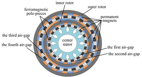
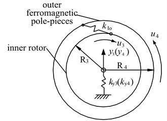
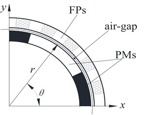
EIMG shown in Fig.1 is composed of the inner stator, the inner and outer ferromagnetic pole-pieces (FPs), the inner rotor, the outer stator and four air-gaps. Three-phase coils are arranged in the inner stator and generate a rotating magnetic field in order to provide power. PMs are arranged uniformly on the inner surface of the outer stator, the inner and outer surfaces of the inner rotor. The inner and outer FPs are composed of the permeability and non-permeability materials at regular intervals. The FPs takes charge of modulating the magnetic fields in two air-gaps beside them in order to make the number of pole pairs of the PMs on the inner and outer rotors agree with the number of pole pairs of the space harmonic flux density of the air-gaps.
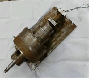
Fig. 1Topology and prototype of the electromechanical integrated magnetic gear
When the outer FPs is fixed, the dynamic model of the EIMG system shown in Fig. 2 contains four subsystems, namely, the inner stator/inner FPs subsystem, the inner FPs/inner rotor subsystem, the inner rotor/outer FPs subsystem and the outer FPs/outer stator subsystem. The electromagnetic coupling dynamic model employs following assumptions [13]:
(1) Main components of the EIMG system are considered to be rigid, assuming that the elastic deformations of PMs, FPs, the rotor and the stator are negligible.
(2) Magnetic interactions among all parts are modeled as the linear spring along tangential direction and normal to their axes. Supports of the inner rotor and the outer FPs can be equivalent to the transverse (i.e. radial) linear spring normal to their axes. Constraints between the inner stator, the inner FPs, the outer stator and the foundation are equivalent to the tangential linear spring and the transverse linear spring, respectively.
(3) Frictional forces among parts are considered to be negligible. Time-varying components of the electromagnetic coupling stiffnesses due to the magnetic field modulating are negligible.
(4) Although the EIMG system has the maximum output torque, out-of-step because of the overload doesn’t occur. Manufacturing and installation errors of all components are not included in this paper.
(5) The effects of the inertias and load waves connected to the EIMG system at the input and output sides are excluded here, considering that these can only cause resonances at very low frequencies.
(6) Amplitudes and frequencies of the electric currents in the inner stator are constants always.
(7) All PMs on the inner and outer surfaces of the inner rotor are assumed to be identical with the same size, performance parameters, respectively. All PMs on the outer stator have the same size, performance parameters too. Magnetic components and non-magnetic components in the inner and outer FPs have the same sizes and performance parameters, respectively.
Fig. 2Dynamic model of the electromechanical integrated magnetic gear
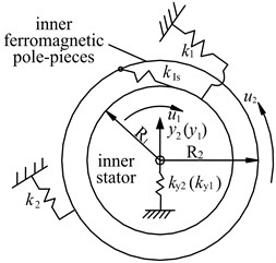
a) The inner stator/inner FPs subsystem
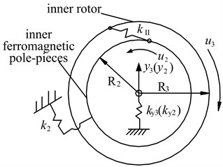
b) The inner FPs/inner rotor subsystem
c) The inner rotor/outer FPs subsystem
d) The outer FPs/outer rotor subsystem
The dynamic model of the EIMG system allows each part translate in directions and rotate about their translation axes. Torsional displacements of the inner stator, the inner FPs, the inner rotor, the outer FPs and the outer stator, are , , , , , respectively. For convenience, the torsional angular displacements are all replaced by their corresponding translational displacements as:
where , are the equivalent radius of gyration of the inner stator, the inner FPs, the inner rotor, the outer FPs and the outer stator, respectively.
Transverse vibration displacements of the inner stator, the inner FPs, the inner rotor, the outer FPs and the outer stator are , , , , , respectively. Then, the generalized displacement vector of the EIMG system can be written as:
2.2. Inner stator/inner FPs subsystem
Fig. 2(a) illustrates the dynamic model of the inner stator/inner FPs subsystem. The undamped differential equations of 4 degrees of freedom (DOF) model of the inner stator/inner FPs subsystem are given as follows:
where and are the masses of the inner stator and the inner FPs, respectively; and are the equivalent masses of the inner stator and the inner FPs along their torsional vibration direction, respectively, , ; and the mass moments of inertia of the inner stator and the inner FPs, respectively, , ; and are the transverse supporting stiffnesses of the inner stator and the inner FPs, respectively; and are the torsional supporting stiffnesses of the inner stator and the inner FPs around their axes, respectively; is the electromagnetic coupling stiffness between the inner stator and the inner FPs, ; and are the radial and tangential components of , respectively; and are the relative displacement and the meshing angle between the inner stator and the inner FPs, respectively, .
The relative displacement between the inner stator and the inner FPs can be calculated as:
By substituting Eq. (2) into Eq. (1), the undamped differential equations of the inner stator/inner FPs subsystem are gotten as follows:
2.3. Inner FPs/inner rotor subsystem
Fig. 2(b) shows the 4 DOF dynamic model of the inner FPs/inner rotor subsystem. The undamped differential equations of the subsystem can be expressed as follows:
where and are the mass and the equivalent mass of the inner rotor, respectively, ; is the mass moment of inertia of the inner rotor, ; is the electromagnetic coupling stiffness between the inner FPs and the inner rotor, ; and are the radial and tangential components of , respectively; is the transverse supporting stiffness of the inner rotor; and are the relative displacement and the meshing angle between the inner FPs and the inner rotor, respectively, .
The relative displacement between the inner rotor and the inner FPs can be calculated as:
By substituting Eq. (5) into Eq. (4), the dynamic differential equations of the inner FPs/inner rotor subsystem are derived:
2.4. Inner rotor/outer FPs subsystem
The 4 DOF dynamic model shown in Fig.2(c) is used to describe the coupling between the inner rotor and the outer FPs. The undamped differential equations of the subsystem can be got:
where and are the mass and the equivalent mass of the outer FPs, respectively, ; is the mass moment of inertia of the outer FPs, ; is the electromagnetic coupling stiffness between the outer FPs and the inner rotor, ; and are the transverse and tangential components of , respectively; is the transverse supporting stiffness of the outer FPs; and are the relative displacement and the meshing angle between the outer FPs and the inner rotor, respectively, ; and are the torque on the inner rotor and the outer FPs, respectively.
The relative displacement between the inner rotor and the outer FPs can be given as:
By substituting Eq. (8) into Eq. (7), the dynamic differential equations of the inner rotor/outer FPs subsystem can be obtained:
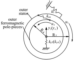
2.5. Outer FPs/outer stator subsystem
The 4 DOF dynamic model shown in Fig. 2(d) illustrates the subsystem of the outer FPs and the outer stator. The undamped differential equations of the subsystem can be expressed:
where and are the mass and the equivalent mass of the outer stator, respectively, ; is the mass moment of inertia of the outer stator, ; is the electromagnetic coupling stiffness between the outer FPs and the outer stator, ; and are the radial and tangential components of , respectively; is the transverse supporting stiffness of the outer stator; and are the relative displacement and the meshing angle between the outer FPs and the outer stator, respectively, ; are the torsional supporting stiffnesses of the outer stator around its axis.
The relative displacement between the outer FPs and the outer stator can be calculated as follows:
By substituting Eq. (11) into Eq. (10), the dynamic differential equations of the outer FPs/outer stator subsystem are:
2.6. The overall system
Eq. (3), Eq. (6), Eq. (9) and Eq. (12), which define the differential equations of individual subsystem, are combined systematically to obtain the differential equations of the overall EIMG system. The undamped differential equations of the 10 DOF of the overall EIMG system can be given in matrix form as:
The mass matrix and the load vector are given respectively as follows:
Because is a 10×10 matrix and bigger, the elements in the matrix can be expressed as follows, respectively:
Free vibration differential equations of the EIMG system are written in matrix form as:
where is a zero vector.
3. Electromagnetic coupling stiffness
All components in the EIMG system are coupled by the electromagnetic field. Here, magnetic circuits are considered to be linear and unsaturated. The two-degree finite element model of the example EIMG system shown in Table 1 can be founded in Ansys. The initial meshes and the magnetic flux density can be calculated and is shown in Fig. 3.
The starting points of the electromagnetic coupling FEM computations of the EIMG system are four basic laws of Maxwell electromagnetic field, namely Ampere circuit law, Gauss law, Faraday’s law of induction and law of continuity of magnetic flux. The whole computational domain is divided into thousands of grid cells. By the variational principle, the partial differential equations are converted to multiple algebraic equations and can be solved by numerical method. The reluctances of the air-gaps are bigger than permanent magnets and the back iron. Meanwhile, the thicknesses of the air-gaps are smaller. So, the grids of the air-gap domains are small and dense.
The meshes on the back iron of the inner rotor and the meshes on the permanent magnets of the inner rotor have common boundary nodes. During running of the EIMG system, all unit nodes on the permanent magnets and the back iron of the inner rotor rotate together as a rigid body. Similarly, the meshes on the back iron of the outer stator and the meshes on the permanent magnets of the outer stator have common boundary nodes. The meshes on the magnetic components and non-magnetic components of the inner and outer FPs have common boundary nodes. The meshes on the magnetic components and non-magnetic components of the outer FPs rotate together as a rigid body. The middle positions of the air-gaps aren’t the common areas of the nodes. During running of the EIMG system, the magnetic field distribution is calculated by interpolations among the boundary nodes. Although there are some errors, the errors are negligible if the meshes of the air-gaps are very small.
Fig. 3The finite element model of the EIMG system
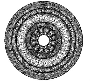
a) Initial meshes of the EIMG system
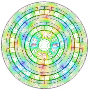
b) Magnetic field distribution
c) Arrangements of PMs segments
The magnetic flux densities of the middle positions of the air-gaps , = 1, 2, 3, 4, 5, can be obtained. and are the radial and tangential components of the magnetic flux densities , respectively. The average torque on each component can be achieved by integrating the Maxwell stress tensor in Ansys. Meanwhile, the electromagnetic coupling forces on all parts can be calculated as follows:
where and , = 1, 2, 3, 4, 5, are the radial and tangential components of the electromagnetic coupling forces, respectively; is the axial length of the EIMG system; , = 1, 2, 3, 4, is the radius of the middle position of the each air-gap; is the space permeability.
The electromagnetic coupling stiffnesses among components can be obtained in Ansys:
where and , = 1, 2, 3, 4, 5, are the radial and tangential components of the electromagnetic coupling forces among components.
When the three-phase alternating currents in the inner stator are switched on, the electromagnetic stiffnesses among components will vary with the relative position angles among components in Ansys and can be worked out in Fig. 4.
Fig. 4Electromagnetic coupling stiffnesses among parts of the EIMG system
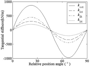
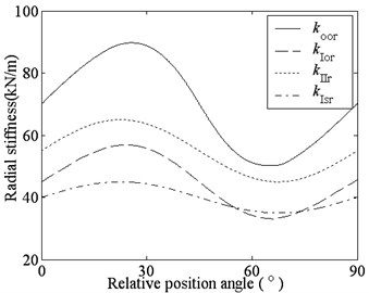
Fig. 4 indicates that the tangential electromagnetic coupling stiffnesses, , , and , vary sinusoidally with the relative position angles among the components. When there isn’t relative rotation between the inner stator and the inner rotor, or between the inner rotor and the outer stator, the EIMG system will stabilize at zero point, also called no-load point or balance point. Now, there isn’t output torque on the outer FPs, namely, the tangential magnetic coupling stiffnesses are zero. The tangential electromagnetic coupling stiffnesses increase with the relative rotation angle among parts increasing. When the relative rotation angle comes to a certain angle, , the tangential electromagnetic coupling stiffnesses will achieve the maxima. Where, is the number of pole pairs of PMs on the inner rotor or the number of pole pairs of the three-phase alternating currents on the inner stator.
Fig. 4 shows that the radial electromagnetic stiffnesses , , and vary sinusoidally with the relative position angles. When the relative rotation angle comes to a certain angle, , the radial electromagnetic coupling stiffnesses will achieve the maxima. But theaverage stiffnesses aren’t zero.
Meanwhile, Fig. 4 indicates that the radial electromagnetic stiffnesses are much smaller than the tangential electromagnetic stiffnesses. This is because magnetic fields in Fig. 3(b) and the radial electromagnetic forces on all parts are nearly evenly distributed along the entire circumference. So, the radial resultant forces are less than tangential resultant forces. Accordingly, the radial electromagnetic stiffnesses are smaller.
Table 1Parameters of example EIMG system
Number of pole pairs on the inner stator | 2 | Number of pole pairs on the inner surface of the inner rotor | 5 |
Number of pole pairs on the outer surface of the inner rotor | 4 | Number of pole pairs on the outer stator | 17 |
Number of the inner ferromagnetic pole pieces | 7 | Number of the outer ferromagnetic pole pieces | 21 |
Outer radius of the inner stator / mm | 98 | Inner radius of the inner FPs / mm | 100 |
Outer radius of the inner FPs / mm | 130 | Thickness of PMs on the inner rotor / mm | 10 |
Inner radius of the inner rotor yoke / mm | 152 | Outer radius of the inner rotor yoke / mm | 182 |
Inner radius of the outer FPs / mm | 204 | Outer radius of the outer FPs / mm | 234 |
Thickness of PMs on the outer stator / mm | 10 | Inner radius of the outer stator yoke / mm | 256 |
Outer radius of the outer stator yoke / mm | 276 | Axial length / mm | 40 |
Remanence of PMs / T | 1.3 | Coercive force of PMs / KOe | 11.6 |
Magnitude of currents on the inner stator / A | 20 |
4. Free vibration of the EIMG system
When the output torque on the outer FPs is the maximum, the electromagnetic coupling stiffnesses among all components will be close to maxima. Now, the characteristic parameters of the EIMG system are shown in Table 2. Substituting the design parameters into the Eq. (14), the natural frequencies and the modal shapes can be worked out in Matlab and shown in Table 3.
Table 2Characteristic parameters of the example EIMG system
(N/m) | (N/m) | (N/m) | (N/m) | (rad) | (rad) | (rad) |
8.6444×10⁵ | 3.1446×10⁵ | 4.5467×10⁵ | 2.0416×10⁵ | 0.1014 | 0.1818 | 0.1435 |
(rad) | (kg) | (kg) | (kg) | (kg) | (kg) | (N/m) |
0.2022 | 1.3 | 1.3 | 11 | 6.2 | 7.7 | 3×10⁶ |
(N/m) | (N/m) | (N/m) | (N/m) | (N/m) | (N/m) | |
3×10⁶ | 3×10⁶ | 3×10⁶ | 3×10⁶ | 3×10⁶ | 3×10⁶ |
Table 3 indicates that there are ten different modes, in which the natural frequencies and the modal shapes are completely different. In the mode shapes corresponding to the natural frequencies 1322.1 rad/s, 1639.2 rad/s 277.2 rad/s, 453.0 rad/s and 832.6 rad/s, the relative deflections of the torsional degree of freedoms (DOFs) are much bigger than the relative deflections of the transverse DOFs. Also, the torsional relative deflection of the inner stator, the inner FPs, the inner rotor, the outer FPs and the outer stator reaches maximum, respectively. Considering the shape characteristics, the above five modes are named the torsional modes of the inner stator, the inner FPs, the inner rotor, the outer FPs and the outer stator (ISRM, IFRM, IRRM, OFRM and OSRM). Other five modes, in which the transverse relative deflections of all parts are much bigger than the torsional relative deflections, are named the transverse modes of the inner stator, the inner FPs, the inner rotor, the outer FPs and the outer stator (ISTM, IFTM, IRTM, OFTM and OSTM).
Table 3Mode frequencies and mode shapes of the EIMG system
Mode type | ISRM | ISTM | IFRM | IFTM | IRRM |
Natural frequencies (rad/s) | 1322.1 | 1529.5 | 1639.2 | 1501.9 | 277.2 |
Mode shapes | -1.0000 0.0326 -0.3773 0.0011 0.0194 0.0017 -0.0015 -0.0002 0.0003 0.0000 | -0.0015 1.0000 0.1705 0.1796 -0.0074 -0.0006 0.0004 0.0000 -0.0000 -0.0000 | 0.4003 0.1331 -1.0000 -0.2413 0.0335 0.0027 -0.0015 -0.0002 0.0001 0.0000 | -0.1691 0.1442 0.4506 -1.0000 -0.0120 -0.0010 0.0006 0.0001 -0.0001 -0.0000 | 0.0489 0.0033 0.2841 0.0125 1.0000 -0.0294 0.6704 -0.0032 0.3670 0.0109 |
Mode type | IRTM | OFRM | OFTM | ORRM | ORTM |
Natural frequencies (rad/s) | 530.6 | 453.0 | 694.2 | 832.6 | 623.5 |
Mode shapes | -0.0186 -0.0012 -0.0956 -0.0039 -0.1608 -1.0000 0.1569 -0.0210 0.1719 -0.0018 | 0.0313 0.0020 0.1688 0.0071 0.5793 -0.1422 -1.0000 0.0598 -0.7975 -0.0120 | 0.0010 0.0001 0.0046 0.0002 0.0129 0.0027 0.0995 -1.0000 -0.2081 -0.0254 | 0.0097 0.0005 0.0370 0.0012 0.0925 0.0140 -0.9268 -0.1766 1.0000 0.0726 | -0.0009 -0.0001 -0.0041 -0.0002 -0.0119 -0.0037 0.0602 -0.0155 -0.1031 1.0000 |
Meanwhile, Table 3 shows that the relative influences among the adjacent components are bigger and the relative vibrations among the intervals components are smaller. Namely, when the resonance of the EIMG system occurs and the displacement of a certain DOF reaches maximum, such as the torsional displacement of the inner rotor, the torsional and transverse displacements of the adjacent components, such as the inner and outer FPs, will be bigger and the displacements of the inner and outer stators will be smaller. This is because all components in the EIMG system are coupled by the magnetic field forces rather than the direct contacts. The weak magnetic coupling forces make the influence among intervals components be smaller.
5. Influence of the design parameters on the natural frequencies
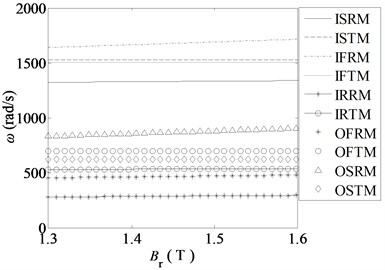
When the design parameters change, the natural frequencies will change too. Fig. 5 shows the influence of the design parameters on the natural frequencies.
(1) Fig. 5(a) shows that all the natural frequencies increase with the remanence of PMs increasing. The natural frequencies of the torsional modes increase obviously, and others are nearly invariable. That is because that the electromagnetic coupling forces and the stiffnesses among components will increase proportionally with increasing. But the radial electromagnetic stiffnesses are smaller than the tangential electromagnetic stiffnesses. When the transverse supporting stiffnesses are almost unchanged, the natural frequencies will change as above.
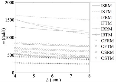
(2) Fig. 5(b) shows that all the natural frequencies decrease when the axial length increases. Especially, the natural frequencies of the ISTM and IFTM decrease greatly. This is because the electromagnetic torques on all the components and the electromagnetic coupling stiffnesses among the components will increase, when the axial length increases. Meanwhile, the masses of all the components increase greatly too. When the torsional and transverse supporting stiffnesses are unchanged, all the natural frequencies decrease.
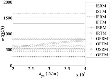
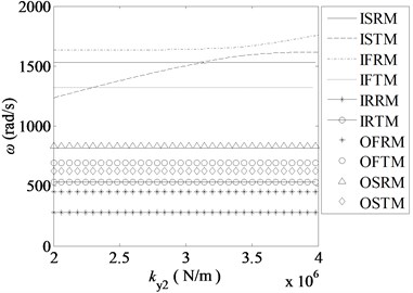
(3) The torsional and transverse supporting stiffnesses will change a lot, when the supporting systems of the components are different. Fig. 5(c) and Fig. 5(d) indicate that the corresponding mode frequency will increase when a certain supporting stiffnesses increases, and other frequencies are similarly constant.
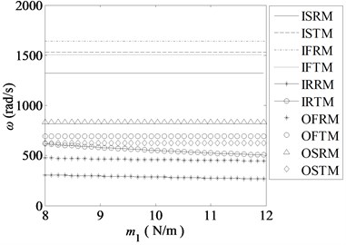
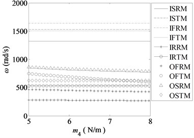
(4) When the structure parameters or materials are different, the masses of the components will also change. Fig. 5(e) and Fig. 5(f) show that only the natural frequencies of the torsional and transverse modes of this component are affected significantly, when the mass of a certain component increases. That is, the mass change of a certain component hardly affects the other natural frequencies of other components.
Fig. 5Changes of the natural frequencies along with the main parameters
a)
b)
c)
d)
e)
f)
In conclusion, the remanence of PMs and the axial length have great influences on the natural frequencies. The supporting systems only affect the vibration frequencies of a certain component. When the space of the EIMG system is certain, the masses of parts change little and has smaller influences on the natural frequencies.
To optimize the dynamic characteristics of the EIMG system and reduce the vibration, the natural frequencies always need be adjusted. On the premise of the enough output capacity, the better options are to change the remanence of PMs and the effective axial length of the EIMG system. When a certain frequency of a component is adjusted, the supporting system can be changed.
6. Conclusion
The electromagnetic coupling stiffnesses in the EIMG system are much smaller than the meshing stiffness of the mechanical gear drive system. The tangential electromagnetic coupling stiffnesses are much bigger than the radial electromagnetic coupling stiffnesses. Meanwhile, the electromagnetic coupling stiffnesses change periodically with the relative rotation angles among components. The EIMG system with four subsystems includes five torsional modes and five transverse modes, which have entirely different modal characteristics. The natural frequencies of the EIMG system are affected greatly by the remanence of PMs and structure size. The component support of a certain part affects the mode frequency of the corresponding component. All these can provide some theory basis for the parameter designs and optimizations of the EIMG system in order to work steadily in a certain working condition.
References
-
Rasmussen P. O., Andersen T. O., Joergense F. T., Nielsen O. Development of a high performance magnetic gear. IEEE Transactions on Industry Applications, Vol. 41, Issue 3, 2005, p. 764-770.
-
Atallah K., Howe D. A novel high-performance magnetic gear. IEEE Transactions on Magnetics, Vol. 37, Issue 4, 2001, p. 2844-2846.
-
Baghli L., Gouda E., Mezni S., Rezzoug A. Hybrid vehicle with a magnetic planetary gear. EFEEA’10 International Symposium on Environment Friendly Energies in Electrical Applications, Ghardaïa, Algeria, 2010.
-
Frank N. W., Toliyat H. A. Gearing ratios of a magnetic gear for marine applications. Electric Ship Technologies Symposium, Maryland, USA, 2009, p. 477-481.
-
Atallah K., Wang J., Howe D. A high-performance linear magnetic gear. Journal of Applied Physics, Vol. 97, Issue 10, 2005, p. N516-N516-3.
-
Niguchi N., Hirata K., Hayakawa Y. Study on transmission torque characteristics of a surface-permanent-magnet-type magnetic gear. IEEJ Transactions on Industry Applications, Vol. 131, Issue 3, 2011, p. 396-402.
-
Jian L. N., Xu G., Song J., Xue H., et al. Optimum design for improving modulating effect of coaxial magnetic gear using response surface methodology and genetic algorithm. Progress In Electromagnetics Research, Vol. 116, 2011, p. 297-312.
-
Du Shiqin, Jiang Jianzhong, Zhang Yuejin, Gong Yu A magnetic gearing. Transactions of China Electrotechnical Society, Vol. 25, Issue 9, 2010, p. 41-46.
-
Percebon L. A., Ferraz R., Ferreira D. L., Mauricio V. Modelling of a magnetic gear considering rotor eccentricity. IEEE International Electric Machines and Drives Conference, 2011, p. 1237-1241.
-
Hao Xiuhong, Yuan Xiaoming, Zhang Hongfei, Zhang Lijie Combination resonances of parametric vibration system of the field modulated magnetic gear. Journal of Vibroengineering, Vol. 16, Issue 3, 2014, p. 1590-1601.
-
Jian Linni, Chau K. T., Jiang J. Z. A magnetic-geared outer-rotor permanent-magnet brushless machine for wind power generation. IEEE Transactions on Industry Applications, Vol. 45, Issue 3, 2009, p. 954-962.
-
Rasmussen P. O., Mortensen H. H., Matzen T. N., et al. Motor integrated permanent magnet gear with a wide torque-speed range. IEEE Energy Conversion Congress and Exposition, 2009, p. 1510-1518.
-
Ahmet Kahraman Free torsional vibration characteristics of compound planetary gear sets. Mechanism and Machine Theory, Vol. 39, 2004, p. 953-971.
About this article

This project is supported by Natural Science Foundation of China (51205341), Research Program of Natural Science at Universities of Hebei province (Q2012032), the Joint Fund of Specialized Research Fund for the Doctoral Program of Higher Education and Hebei Provincial Education Office (20121333120004).
