Abstract
In deep rock blasting, there are different constraint conditions such as unidirectional loading, bidirectional loading and tridirectional loading due to in-situ stress. The similar model test of rock blasting under unidirectional load was carry out to study the law of crack propagation in rock by blasting in this study. A transparent material which conformed to the mechanical properties of hard rock is used to make specimens. A high-speed camera was used in some model blasts. After blasting the surface cracks on the specimen were measured, including the near zone and middle zone of blasting. The results showed that: (1) the radial main cracks in the specimens under initial static load propagated along the principal stress direction, which is different from that without initial stress, and there is almost no radial main crack in the direction perpendicular to the principal stress. (2) The average length of radial crack and diameter of circumferential fracture circle gradually decrease with the increase of unidirectional initial stress, but the diameter of compression crushing circle increase. (3) The maximum and average initial velocity of radial crack growth decrease with the increase of unidirectional initial stress.
Highlights
- A transparent material which conformed to the mechanical properties of hard rock was used to carry out the similar model test of rock blasting.
- The effect of unidirectional initial stress on the propagation velocity for radial main crack was analyzed.
- A mechanical model for blasting-induced radial main crack propagation under unidirectional initial stress was established.
1. Introduction
With the transformation of modern mine mining from shallow to deep, rock mass exists in the environment with high in-situ stress. It leads to changes in the theory of rock blasting and crushing and the stability mechanism of surrounding rock in deep mine compared with that in shallow mine, which urgently needs to be improved and enriched [1].
Many studies have been carried out on the influence of in-situ stress field on cracking of rock mass and effect of rock fragmentation by blasting [2-7]. Such as, Yang et al. [8] studied the dynamic mechanical behavior of crack initiation and propagation by blasting with the situation of blasthole through rock bedding under the state of high in-situ stress by using laboratory model experiment. In order to study the dynamic mechanical behavior of main crack in slotted cartridge blasting under the action of unidirectional confining pressure, Yue et al. [9] used a new digital laser dynamic caustics experimental system to carry out several groups of blasting optical measurement experiments. In addition, Yang et al. [10] used numerical simulation method of smoothed particle hydrodynamics coupled with finite element method (SPH-FEM) to study the propagation and penetration process of cracks between blastholes under high in-situ stress, and analyzed the dynamic evolution process and distribution characteristics of stress field around blastholes.
In the experiment and production practice, it was found that hole blasting in the medium with dynamic and static stress fields presented a few of phenomena for preferential crack initiation, good blasting effect and low explosive consumption, which Zhang described as “waveguide effect” [11]. He believed that the dynamic response of rock mass would be changed due to the existence of complex in-situ stress in the rock mass. In this regard, Xiao [12] proposed the principle that the initial stress field had a “guiding effect” on the propagation of cracks. In summary, researchers generally believed that the propagation direction of crack in rock by blasting under the condition of in-situ stress was toward to the direction of maximum principal stress [13, 14], but they hold different views on its mechanism, which was still controversial.
In addition, the most of current research results were about the influence of in-situ stress on the longest main crack, while there were few studies on the effect of in-situ stress on the circumferential fractured zone in middle blasting area. Therefore, the blasting model test of transparent rock under the action of confining pressure in this study was carried out to study the mechanism of in-situ stress on crack propagation by blasting, and reveal the law of the in-situ stress effecting on the direction, length and speed of crack propagation by blasting, as well as diameter of the circumferential fractured zone in middle blasting area.
2. Experiments
2.1. Test device
The in-situ stress constrained on deep rock mass is simulated by using a self-developed device for model test, which has plane stress loading system, data measurement system and high-speed photography system [15]. The device consists of three parts, which are stress loading platform, oil pressure station, high-speed camera suspension, as shown in Fig. 1.
The stress loading platform can provide confining stress for model specimens with the maximum size of 500 mm×500 mm×100 mm (length×width×height). The rated power of oil pressure station used for loading platform is 5 MPa, the extreme power is 7 MPa, and the piston area of a single oil cylinder is 7.065 cm2. If this device is used to load model specimens with the size of 300 mm×300 mm×20 mm, the rated load concentration and ultimate load concentration that could be reached inside the specimen were 1.1775 MPa and 1.6485 MPa respectively, which basically satisfied the uniform condition of stress field in the model.
Fig. 1Device for plane stress loading on model specimen
2.2. Similarity coefficient
The deep roadway project of Dingji Coal Mine in Huainan mining area is taken as the prototype for model test. The in-situ stress field in this mining area is mainly dominated by horizontal tectonic stress [16]. The buried depth of roadway is 910 m [17], the cross-section shape of which is semicircular arch, and the cross-section size is 5000 mm×3880 mm. The roadway is mainly located in the stratum of medium sandstone and siltstone, and the physical and mechanical parameters of protolith are shown in Table 1.
Table 1Physico-mechanical parameters of prototype rock
Material type | / KN∙m-3 | / GPa | / MPa | / ° | / MPa | / MPa | |
Sandstone | 27 | 12.97 | 10.00 | 43 | 0.268 | 135 | 21.5 |
Note: – bulk density, – deformation modulus, – cohesion, – internal friction angle / (°), – Poisson’s ratio, – compressive strength, – tensile strength | |||||||
At present, the most commonly similar material used in experiments of rock blasting is cement mortar [18]. However, the cracks cannot be directly observed in models made by cement mortar after blasting. Therefore, a kind of transparent hard rock-like material was used to make models in this study. This transparent hard rock-like material is made of a mixture of rosin saturated solution (RSS), epoxy resin (ER) and curing agent (CA), and its physical and mechanical properties are similar to those of hard rock through relevant tests [19]. The basic physical and mechanical parameters are shown in detail in Table 2.
Table 2Basic mechanical parameters of transparent rock-like materials
Physical quantities | / MPa | / MPa | / MPa | |||
Numerical value | 1230 | 2423 | 360-1802 | 0.26-0.31 | 3.29-96 | 0.259-7.22 |
Note: – density / kg∙m-3, – compressional wave velocity / (m/s) | ||||||
In similar systems, the ratio of the same physical quantities is called similarity ratio, that is, “prototype physical quantity ()/model physical quantity () = similarity ratio ()” [20]. The similarity relation between various physical quantities of model test can be obtained as:
The geometric similarity coefficient selected for model tests is 16.7 () in this study. The similarity coefficient for bulk density could be calculated that 2.2. Hence, it can be calculated by above formulas as 36.7 (stress similarity coefficient), 36.7 (elastic modulus similarity coefficient), 36.7 (cohesion similarity coefficient), 4.15 (time similarity coefficient).
2.3. Blasting charge
It had been shown that using uncoupled charge in rock blasting can enlarge the range of fractured zone and make full use of explosive energy [21-24]. The method of uncoupled charge is used in model test for rock blasting, and the diameter for blasthole is designed to be 4 mm, the diameter for charging is 3 mm, and the height for charging is 20 mm. A relatively safe and stable small detonator is selected as the explosive in this test, and its main component is DDNP. The prototype explosive is a three-level permissible water-gel explosive for coal mine, with a density of 1.1 g/cm3 and a detonation speed of 3600 m/s. The model explosive is DDNP in bulk, with a density of about 0.7 g/cm3 and a detonation speed of 5400 m/s. It can be obtained through calculation that 1.047 is the density ratio of prototype explosive to model explosive, and is the detonation velocity ratio of prototype explosive to model explosive), which basically meets the principle of “similar blasting energy of explosives” [25]. The detailed charging structure is shown in Fig. 2.
Fig. 2Schematic diagram for charging structure
It can be seen from Fig. 2, the blasthole for charging is located in the center of specimen, and the two ends of it are bonded with 1 mm thick plastic discs, which are used for fixing the special small detonator.
2.4. Test scheme
According to the making method for transparent hard rock-like material [19], flat plate specimens with a size of 300 mm×300 mm×20 mm are made for blasting model tests by use the mass ratio of 10:10:1 (namely epoxy resin: curing agent: saturated rosin solution).
The buried depth of simulated rock mass designed in tests is from 0 m to 1600 m, so the corresponding loading stress values simulated confining pressure of vertical is from 0 MPa to 1.168 MPa according to 36.7 (stress similarity coefficient) and (vertical stress). The four groups of loading schemes designed in actual model tests are shown in Table 3.
Table 3Test scheme for blasting of transparent model specimens
Specimen number | Buried depth / m | design / MPa | loading / MPa |
TFG-0 | 0 | 0 | 0 |
TFG-1 | 400 | 0.3 | 1.2 |
TFG-2 | 1000 | 0.743 | 3.1 |
TFG-3 | 1600 | 1.168 | 4.8 |
Note: – confining pressure | |||
3. Results and analysis
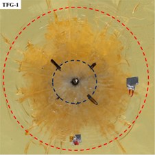
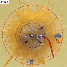
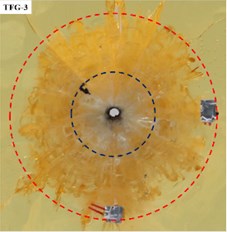
As shown in Fig. 3, it was the model specimen after explosive explosion, where the propagation of cracks by blasting could be clearly observed.
Fig. 3Transparent model specimens after explosion
a) = 0 MPa
b)= 1.2 MPa
c)= 3.1 MPa
d)= 4.8 MPa
Based on the existing explosion theory after explosion of explosives embedded in infinite rocks [26, 27], different damage zones from near to far with charge as the center would be produced in rocks. According to the characteristics of the fractures in the rock surrounding a blasthole, the rock damage region was divided into a crushed zone, a fractured and an elastic vibration zone [28].
It can be seen from Fig. 3, the postblast specimens displayed a wide range of damage. The damage area in specimen TFG-0 after explosion with uncoupled charge was divided into crushed zone (Ⅰ), fractured zone (Ⅱ and Ⅲ) and elastic vibration zone (Ⅳ), which was basically consistent with the phenomenon and conclusion of current single-hole blasting test [29].
By comparing Fig. 3(a-d), it was found that the radial main cracks in specimen (TFG-1) without initial stress loading propagated radially, while the radial main cracks in specimens (TFG-2, TFG-3 and TFG-4) with initial stress loading propagated mainly along the direction of principal stress. This indicated that the initial static stress could affect or change the propagation direction of radial main crack and make it propagate toward to the direction of principal stress.
With the increase of vertical load applied to specimens (TFG-1, TFG-2 and TFG-3), the total area of crushed zone (Ⅰ) and fractured zone (II and III) was decreasing, whereas the area of vibration zone (IV) was expanding. It was obvious that there were seven radial main cracks in specimen TFG-0, three radial main cracks in specimen TFG-1 and specimen TFG-2, but there were only two radial main cracks in specimen TFG-3. At the same time, the included angle between the two radial main cracks in specimen TFG-2 was significantly reduced compared with that in specimen TFG-1.
In order to study the influence of confining pressure load on the fractured zone, it was divided into two parts – Ⅱ and Ⅲ in the present investigation and was shown in Fig. 3(a). Part Ⅱ of fractured zone referred to the area where the circumferential cracks and radial cracks intersect, while part Ⅲ of fractured zone actually referred to the area of only radial cracks. The part Ⅱ of fractured zone and crushed zone from each model specimen were intercepted as shown in Fig. 4, where the blue line was marked as crushed zone and red line was marked as part Ⅱ of fractured zone.
Fig. 4Part Ⅱ of fractured zone and crushed zone on four specimens
a)
b)
c)
d)
Through the measuring on diameters of the boreholes for the specimens (Fig. 4) after being subjected to the action of the explosion shock wave, it was found that the boreholes were expanded to varying degrees. For TFG-0, TFG-1, TFG-2 and TFG-3, with the same charge weight of approximately 0.052 g and initial borehole diameter of 4 mm, the determined diameters of the postblast boreholes were 4.7 mm, 4.1 mm, 4.37 mm, and 4.57 mm, respectively. Obviously, borehole expansion without confining pressure load was larger than that under confining pressure load, and the borehole expansion under confining pressure increased with the increase of vertical stress.
In addition, the measurement for diameter of crushed zone in postblast model specimens showed that the initial in-situ stress had a great effect on crushed zone. For instance, the diameter of crushed zone without initial stress was 2.34 cm (TFG-0); under the state with initial stress, the diameters of crushed zone increased from 1.85 cm (TFG-1) to 2.24 cm (TFG-3) with the increase of vertical stress. Apparently, the above measurement results also showed that the expansion of crushed zone are “suppressed” by the initial stress, and there was a positive correlation between diameter of crushed zone and vertical stress.
3.1. Effect of initial stress on crack propagation in fractured zone
Fractured zone was contribute to main part of rock fragmentation by blasting in engineering, the failure range of which was much larger than that of crushed zone. The length, velocity of crack and damage range in fractured zone played an important role in determining delay time, designing a blast and understanding the mechanism of rock fragmentation by blasting [30]. Therefore, the influences of initial stress on crack length, crack velocity, and damage range were analyzed in detail in the following sections.
3.1.1. Effect on part Ⅱ
As the load was only applied on the model specimens in direction of vertical, the boundary conditions of model specimen were different in each direction [31]. Hence, the effect of initial stress on the diameter of Part Ⅱ was divided into vertical direction and horizontal direction to discuss. The diameters of Part Ⅱ in fractured zone of specimens were measured, as shown in Table 4.
Table 4Diameters of Part Ⅱ in fractured zone
Number of specimens | Diameters of Part Ⅱ /cm | ||
Along the direction of | Perpendicular to the direction of | Mean value | |
TFG-0 | 9.3 | 9.3 | 9.3 |
TFG-1 | 8.2 | 8.4 | 8.3 |
TFG-2 | 7.3 | 7.5 | 7.4 |
TFG-3 | 7.2 | 7.4 | 7.3 |
It can be seen from Table 4 that the diameters for part Ⅱ of fractured zone varied with the boundary conditions of model specimens. Under the condition of no confining pressure (specimen TFG-0), the diameters along the stress direction and perpendicular to the stress direction for part Ⅱ of fractured zone were equal. However, under the confining pressure load (specimen TFG-1, TFG-2 and TFG-3), the diameters in the horizontal direction and the vertical direction were not equal, and the diameters in the horizontal direction were smaller than that in the vertical direction.
At the same time, it can be found that with the increase of vertical load, the diameters for part Ⅱ of fractured zone decreased gradually, which indicated that vertical load applied on the model specimens not only restrained crack propagation in the direction of , but also restrained the crack propagation perpendicular to the direction of .
According to the studies of Qian and Li [32, 33], the initial static load applied on the specimens along the vertical direction had a constraint effect on the rock, so that the dynamic compressive strength of surrounding rock along this direction was increased. The current blasting theory believes that cracks in Part Ⅱ of fractured zone are mainly caused by the loading and unloading action of compression stress wave on the surrounding rock of the borehole. However, the strengthening for the strength of surrounding rock in direction of vertical lead to the weakening of the loading and unloading damage of compression stress wave on rock around blasthole, which result in that the diameters for Part Ⅱ of fractured zone in the direction of vertical were relatively smaller compared with that in the direction of horizontal.
3.1.2. Effect on part Ⅲ
According to postblast model specimens (Fig. 3), the propagation law for the longest main crack on each specimen could be obtained, as shown in Fig. 5.
Fig. 5 showed that the length of the longest main crack decreased with the increase of vertical stress, and the direction of the longest crack propagation was closer to the direction of stress loading with the increase of stress. According to the measurement results, the Angle between the longest main crack of TFG-0 and the vertical axis was 45, while the Angle between TFG-1, TFG-2 and TFG-3 and the vertical axis decreased gradually with the increase of stress, which were 30, 20 and 0in turn.
In order to characterize the variation of radial main crack length with unidirectional initial stress applied on model specimens, some radial cracks from four postblast specimens were selected to measure. The results for measuring were shown in Table 5, where the number of radial main cracks selected from each postblast specimen was equal.
Fig. 5Distribution of the longest main crack in postblast model specimen
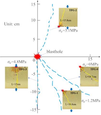
Table 5Statistics for radial main crack length in model specimens
Number of specimens | Length of radial main cracks / cm | Mean value / cm | ||||
1# | 2# | 3# | 4# | 5# | ||
TFG-0 | 14.8 | 16.0 | 18.7 | 16.8 | 16.5 | 16.6 |
TFG-1 | 15 | 9.7 | 6.8 | 15.8 | 16.6 | 12.8 |
TFG-2 | 15.2 | 9.6 | 15.2 | 7.1 | 15.8 | 12.6 |
TFG-3 | 15 | 7.8 | 9.5 | 15 | 8.2 | 11.1 |
Note: Cracks 1#∼5# are the top five in length of radial main cracks on model specimens | ||||||
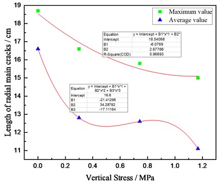
Table 5 showed that the average length of radial main cracks decreased successively from specimen TFG-0 to specimen TFG-3. The data in Table 5 were plotted in Fig. 6, which could be obtained the relationship between vertical stress and length of the main cracks.
It can be clearly seen from Fig. 6 that both the length of longest main crack and average length of cracks decreased with the increase of stress, which fully indicates that the initial stress can suppress crack propagation of radial main crack. According to the results for data fitting, the relationship between the vertical stress and length of main cracks was as follows:
where represented the vertical stress; y represented the maximum length of main cracks.
Based on the analysis of model test results in sections (1) and (2), it can be seen that the initial stress had different effects on part Ⅱ and part Ⅲ of fractured zone. For part Ⅱ of fractured zone in postblast model specimens, the diameter of which along the direction of stress loading were smaller than that perpendicular to the direction of stress loading. However, for part Ⅲ of fractured zone in postblast model specimens, the propagation length of main cracks along the direction of stress loading was much longer than that perpendicular to the direction of stress loading.
Fig. 6Length of blasting-induced main cracks vs loading stress
3.2. Effect of initial stress on fracture and damage energy
Previous researches showed that rocks under an external force would undergo stages such as microcrack closure, elastic deformation, microdefect evolution and expansion and catastrophic failure. During these stages, the rocks were always exchanging energy with the surrounding environment, converting the mechanical energy from the surrounding environment into strain energy and thermal energy and store them as their own internal energy; at the same time, the strain energy was converted into plastic energy and surface energy etc. and energy was released in the forms of electromagnetic radiation, acoustic emission and kinetic energy [34, 35]. Therefore the “energy” can be considered as a parameter appeared in the whole process of rock deformation and fragmentation [36, 37].
The energy distribution of rock fragmentation by blasting mainly includes: the energy for rock fracture damage, the energy for blasting vibration, the energy of escaping and other forms of dissipated energy, such as thermal energy and radiation energy [38]. And the distance between rock mass and source of detonation determines the amount of explosive energy received by rock mass. In other words, the rock mass which is close to the source of detonation would receive more explosive energy and be broken more finely. However, due to the great attenuation of stress energy, the rock mass which is far away from the source of detonation would receive less explosive energy, which leads to fewer broken layers and correspondingly coarser particle size of rock mass.
In this study, the relationship between crack area and energy of rock fracture damage was established to characterize the effect of initial in-situ stress on the energy used for rock mass fracture damage. Meanwhile, according to the difference of rock mass distance from detonation source, it was assumed that the energy absorbed by crushed zone per unit area was KJ /m2, the energy absorbed by Part Ⅱ of fractured zone per unit area was KJ /m2, and the energy absorbed by Part Ⅲ of fractured zone per unit area of was KJ /m2 (). Therefore, the explosion energy consumed by fracture damage zone of specimens was that area of damage or fracture times energy dissipated per unit area. According to Fig. 3, the crushed zone and fractured zone were reconstructed as shown in the Fig. 7.
In the figure above, the , and were used to indicate the area of crushed zone, Part Ⅱ of fractured zone and Part Ⅲ of fractured zone, respectively. It should be noted here that, for the convenience of calculation in this study, the range of fracture and damage for Part Ⅲ of fractured zone was considered to be the area surrounded by the blue main cracks and the yellow lines. The area of fractured and crushed zone on specimens after blasting can be calculated based on Fig. 7, and the results of calculation were shown in Table 6.
Fig. 7Crushed zone and fractured zone vs loading stress
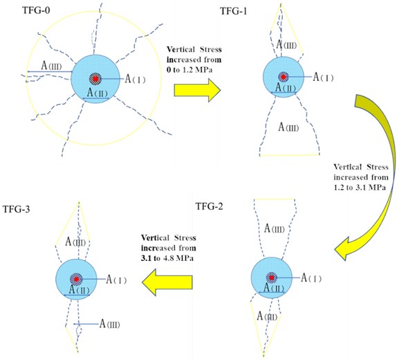
Table 6The area of fractured and crushed zone on specimens
Number | / cm2 | / cm2 | / cm2 | Total area / cm2 |
TFG-0 | 4.166 | 63.08 | 480.1 | 547.4 |
TFG-1 | 2.564 | 51.54 | 119.4 | 173.5 |
TFG-2 | 3.481 | 39.53 | 98.68 | 141.7 |
TFG-3 | 3.816 | 38.04 | 61.14 | 101.0 |
It can be seen from Table 6 that with the increase of stress, the total area of fracture damage zone decreased gradually, which indicated that the energy produced by the explosion of an explosive was used to and damage less and less.
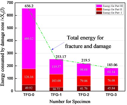
The study had shown that the formation of fines and severe fracturing are important factors in rock blasting as both processes consume a great amount of energy [39]. Furthermore, Cunningham et al. concluded that close to half or even more of the total explosive energy was consumed for the borehole expansion. Accordingly, it is assumed that in this study, so that the energy consumed in the damage zone of each specimen can be expressed as follows:
It was obvious from Fig. 8 that the total energy used for fracture and damage gradually decreased with the increase of stress applied to the specimens TFG-0, TFG-1, TFG-2 and TFG-3. The results also showed that the total energy consumed for fracture and damage of specimens under the state of no stress loading was greater than that under the state of stress loading. In terms of the energy consumed in the crushed zone, the energy consumption in the non-stress state was larger than that in the stress state, but the proportion for energy consumption of crushed zone increased with the increase of stress (energy proportion: the energy consumed in the crushed zone accounts for the total energy used for fracture and damage). For the fractured zone (both Part Ⅱ and Part Ⅲ), the energy consumption decreased with the increase of stress, and the proportion of energy consumption to total energy used for fracture and damage also decreased.
Fig. 8Energy distribution of crushed zone and fractured zone
According to the study on attenuation mechanism of stress wave in intact rock under confining pressure by Liu [40], there are a large number of microcracks in intact rock, where stress waves propagating through intact rock will force microcracks to overcome friction and produce sliding. In this process, part of the energy of the stress wave is converted into thermal energy, resulting in the decrease of its energy dissipation wave amplitude. The confining pressure can make the microcracks inside the rock close, thus increasing the friction force that drives them to slide, resulting in the reduction of the number of microcracks that can slide under the action of stress waves, which finally reduces the attenuation of the stress wave. This means that the increase of confining pressure will make the energy of stress wave transform into thermal energy inside rock mass and the vibration energy in far zone of blasting more.
As can be seen from Section 2.2, the same charge amount was adopted in this experiment, which means that the total energy of explosive explosion under different conditions of stress was equal. In addition, the same charging structure was used in each model specimen, so it can be roughly considered that the energy of escaping of each specimen is approximately the same. Therefore, the reduced total energy used for fracture and damage under stress state is just converted into the thermal energy generated in rock mass and vibration energy in the distant zone of blasting, which is consistent with the research results of Xu [41].
In summary, it can be concluded that the initial stress changed the distribution of explosion energy, that is, the total energy used for rock fragmentation by blasting was reduced, the proportion of energy used for crushed zone was increased, and the proportion of energy used for fractured zone was decreased.
3.3. Effect of vertical stress on the propagation velocity of main crack by blasting
The effect of unidirectional initial stress on the propagation velocity for radial main crack was analyzed by using the photos of crack propagation at different times recorded by a high-speed camera during the test. The high-speed camera (Memrecam HX-3E) produced by NAC company was used in the experiment, and 8,000 images were collected per second. The pictures captured by high-speed camera in the two states before and during blasting were shown in Fig. 9.
Due to the limitation of the equipment, the images shown by the lens are crushed zone and fractured zone near the blasthole on the model specimen. Therefore, it can be only calculated the crack propagation velocity in these two zones to discuss the influence of unidirectional initial stress on it. The propagation velocities from 0 μs to 125 μs for radial main cracks of the four model specimens were calculated according to the position of crack tip recorded on the high-speed camera at different times, and the calculated results were summarized in Table 7.
Fig. 9High-speed photographs at times 0 μs, 125 μs, and 250 μs
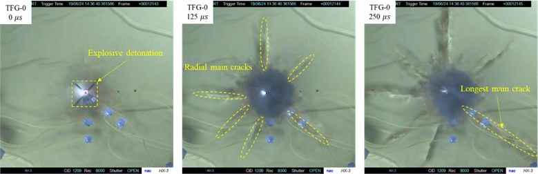
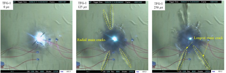
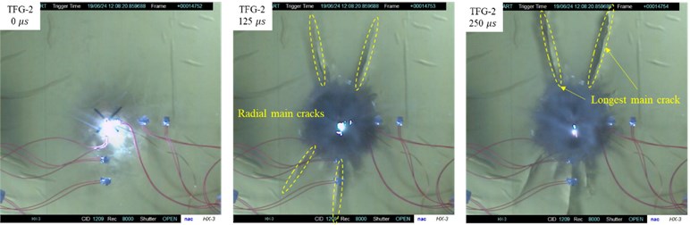
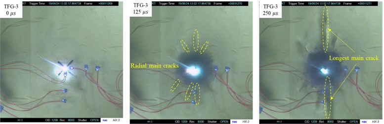
Table 7Propagation velocity of radial main cracks
Number of specimens | Propagation velocity /(m/s) | |||
1# | 2# | 3# | Mean value | |
TFG-0 | 679.5 | 640.1 | 538.6 | 619.4 |
TFG-1 | 563.6 | 442.2 | 433.6 | 479.8 |
TFG-2 | 511.3 | 511.3 | 383.5 | 468.7 |
TFG-3 | 346.9 | 303.5 | 251.5 | 300.6 |
Note: Cracks 1#∼3# are the top three in length of radial main cracks on model specimens from 0 μs to 125 μs | ||||
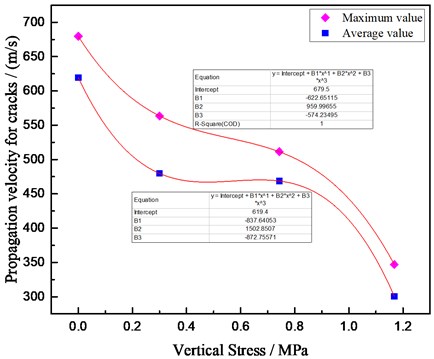
The data in Table 7 were plotted into the propagation velocity-stress curve of radial cracks, as shown in Fig. 10.
As can be seen from Fig. 10, both the maximum and average initial velocities of radial cracks propagation decreased with the increase of unidirectional initial stress. Thus, it can be obtained that the initial stress also had a “suppression” effect on the propagation velocity of main cracks by blasting. The data fitting results showed that there was a polynomial function relationship between propagation velocity of cracks and vertical stress, as shown in the following equation:
where represented the vertical stress; y represented the propagation velocity of cracks.
Fig. 10Propagation velocity of radial crack vs vertical stress
4. Discussions
Plane blasting model tests were used in Section 3 of this study. Due to the poor actual sealing effect of the boreholes, the leakage of explosive gas was more serious, which reduced the cracking effect of the explosive gas on the specimens. Therefore, it is considered that the blasting cracks in the specimens were caused by the effect of stress wave.
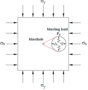
Classical blasting theory has clarified that the propagation of the radial main crack located in the Part Ⅲ of fractured zone is mainly caused by the circum-tensile stress wave derived from compressive stress wave. However, the test results in Section 3 of this study show that the propagation law of main crack changes greatly under the action of initial static stress compared with that without initial static stress. Therefore, the combination of dynamic and static loading (as shown in Fig. 11) was used to simulate the stress state of deep rock mass engineering to explore the action mechanism of initial static load on crack propagation by blasting in this study [42].
It is assumed that the initial stress of rock mass in vertical direction is , the initial stress in the horizontal direction is , the internal explosion load is , and the compressive strength and tensile strength of the rock are , respectively.
When the rock in the state of static in-situ stresses was subjected to the dynamic loading of explosive explosion, it would start to damage at a certain time. In this process, the effect of in-situ stress on the rock was usually regarded as quasi-static loading. Moreover, blasting model test only under vertical load were carried out in the experimental part of this study. In this case, the force model could be simplified as shown in Fig. 12, and the explosion load was described by , (). Generally, the rock mass in fractured zone was subjected to dynamic load of stress wave. In order to facilitate the analysis, the stress wave in model within the same radius of fractured zone (the crack was still in propagation) at a certain moment was described by , (), and a point taken from each of the four different directions was denoted as , , , and .
Fig. 11Force model of deep rock mass under blasting
According to the existing blasting theory, when the circumferential tensile stress derived from blasting stress wave was greater than the tensile strength of rock, there will be produced the radial cracks in rock. Therefore, the above four points are also affected by circumferential tensile stresses, which were described by and . At the same time, it is assumed that . In this way, the dynamic load was also simplified to the static load (as shown in Fig. 12). In this case, stress analysis can be carried out according to the plane stress problem in the theory of elastic mechanics.
Fig. 12Force model of deep rock mass under blasting at a certain moment
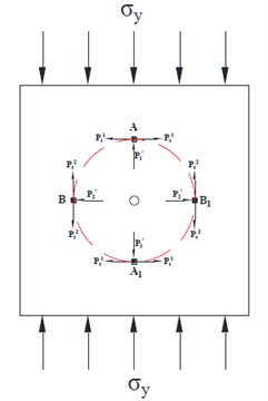
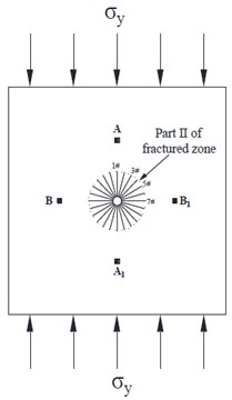
Fig. 13Force model for Part Ⅱ of fractured zone of deep rock mass
(1) Internal stress analysis of the model under vertical load.
From the experimental results in the section 3, it can be seen that there are circular crushed zone and Part Ⅱ of fractured zone on each specimen under the conditions with different initial stress, which indicates that the loading and unloading effect of blasting stress wave on the model specimen was much greater than the tensile and compressive strength of the specimen under initial stress. Therefore, it can be assumed that under the combined action of the blasting stress wave and the initial stress, cracks would occur along all directions in crushed zone and Part Ⅱ of fractured zone of model specimen, as shown in Fig. 13.
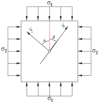
According to the Griffith crack mathematical model for the propagation of a closed crack under pressure, a Griffith crack of size 2 in an infinite linear elastic plate was investigated. The edge was subjected to uniform biaxial pressures and , and the Angle between the crack direction and the action direction of was (called crack Angle). The rectangular coordinate system was established, where the -axis was parallel to the direction of the crack, and the -axis coincides with the vertical line of the crack (Fig. 14). By coordinate transformation of the stress component, the stress state in the far field was:
Fig. 14Griffith crack model for the propagation of a closed crack under pressure
In this way, the far-field stress at the tip of cracks can be calculated when the Angle changes from 0 to 90. The detailed calculation results were shown in the Table 8.
Table 8Far-field stress at the tip of cracks of Part Ⅱ in fractured zone
Internal stress | Number of cracks | ||||||
1# | 2# | 3# | 4# | 5# | 6# | 7# | |
/ MPa | 0.93 | 0.75 | 0.5 | 0.25 | 0.067 | 0 | |
/ MPa | 0 | 0.067 | 0.25 | 0.5 | 0.75 | 0.93 | |
/ MPa | 0 | 0.25 | 0.43 | 0.5 | 0.43 | 0.25 | 0 |
Note: The angle between the direction of crack 1# and the direction of vertical stress is 0, angle for 2# is 15, and so on, the angle for crack 7# is 90 | |||||||
(2) Force analysis of model under the coupling action of blasting load and vertical stress.
When the model specimens were only subjected to static stress loading, the specimens had not been damaged, indicating that the shear stress inside the specimens was not enough to cause the shear failure on the specimens. Hence, the effect of shear stress on the crack propagation in Part Ⅱ of fractured zone on the model specimens was ignored in this study. According to the values calculated in Table 8, the force analysis on the infinitesimal points A and B in Fig. 10 can be obtained shown in Fig. 15.
Obviously, the force model shown in Fig. 12 is a symmetrical structure, so the stress analysis on the above four force points can be carried out according to two parts of A/A1 and B/B1. According to Fig. 15, the forces acting on A/A1 can be obtained as follows:
When , there will be produced tensile failure in the rock mass. When , there will be produced compression failure in the rock mass. The existing blasting theory has pointed out a fact that the blasting stress wave in the fracture zone is no longer enough to crush the rock mass, so the stress wave weakened by the initial stress is more unlikely to produce any compression failure on rock mass in the vertical direction of points A/A1. For points A/A1, it is only necessary to discuss the horizontal tensile stress.
Fig. 15Force analysis for infinitesimal points in rock mass
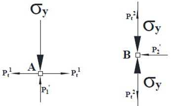
According to Fig. 15, the forces acting on B/B1 can be obtained as follows:
Same as above analysis, it is impossible to generate any compression failure on rock mass in the horizontal direction of points B/B1. For points B/B1, it is only necessary to discuss the vertical tensile stress.
By comparing the tensile stress at points A/A1 () with the tensile stress at points B/B1 (), it is found that: . It has been informed in the hypothesis that all the taken points are from the fracture zone (radial cracks are in propagation) and are at the same distance from the blast center. Therefore, with the further attenuation of stress wave, there must be a situation that . It can be concluded that the crack along AA1 direction will continue to propagate after the stopped propagating for crack along BB1 direction. In other words, the total length of the crack in the direction of AA1 is greater than the total length of the crack in the direction of BB1. On the macro level, the radial crack propagates along the direction of principal stress, that is, the initial stress has a “guiding effect”.
5. Conclusions
In this study, similar model tests of rock blasting under unidirectional load were carried out with transparent model materials. Based on the results of model tests, the law for the effect of unidirectional initial stress on propagation of blasting-induced crack was analyzed. At the same time, a mechanical model for blasting-induced radial main crack propagation under unidirectional initial stress was established, based on Griffith crack mathematical model for the propagation of a closed crack under pressure and basic theory of rock fragmentation by blasting. Thus, it was carried out to obtain the influence mechanism of initial stress on the direction of crack propagation. The research results are of great practical significance for correctly understanding the law of crack propagation in rock mass by blasting under high in-situ stress and enriching the theory of rock fragmentation by blasting. The conclusions obtained from this study are summarized as follows:
1) The initial stress affected the propagation direction of radial main cracks. Under the action of the combined dynamic and static loads, the propagation direction of radial main cracks of model specimens was changed from the radial direction (without initial stress) to the direction of vertical stress. With the increase of the load on the specimens, the number of radial main cracks gradually decreased, and finally the radial main cracks only propagated along the loading direction.
2) The initial stress also suppressed the propagation length and velocity of radial main cracks. With the increase of vertical load, the length of radial cracks propagating along the direction of vertical stress was less affected, while the radial cracks propagation far away from the direction of vertical stress was more and more restricted. As a whole, the propagation of radial main cracks was suppressed by vertical stress. In addition, the propagation velocity of radial main cracks and the diameters of Part Ⅱ on fractured zone and crushed zone decrease with the increase of vertical stress.
Although some meaningful conclusions have been drawn in this study, which enriches the theory of rock fragmentation by blasting in deep rock mass and can also provide reference for engineering practice, there is still a big gap between this study and practical rock blasting in deep rock because it is only carried out on the basis of blasting model test under unidirectional load. Therefore, it is necessary to focus on the study of mechanism for rock blasting under tridirectional loads in the next study.
References
-
W. Lu, M. Chen, X. Geng, D. Shu, and C. Zhou, “A study of excavation sequence and contour blasting method for underground powerhouses of hydropower stations,” Tunnelling and Underground Space Technology, Vol. 29, No. 5, pp. 31–39, May 2012, https://doi.org/10.1016/j.tust.2011.12.008
-
C. Yi, D. Johansson, and J. Greberg, “Effects of in-situ stresses on the fracturing of rock by blasting,” Computers and Geotechnics, Vol. 104, No. 12, pp. 321–330, Dec. 2018, https://doi.org/10.1016/j.compgeo.2017.12.004
-
L.-Y. Yang and C.-X. Ding, “Fracture mechanism due to blast-imposed loading under high static stress conditions,” International Journal of Rock Mechanics and Mining Sciences, Vol. 107, No. 7, pp. 150–158, Jul. 2018, https://doi.org/10.1016/j.ijrmms.2018.04.039
-
R. Yang, C. Ding, L. Yang, and C. Chen, “Model experiment on dynamic behavior of jointed rock mass under blasting at high-stress conditions,” Tunnelling and Underground Space Technology, Vol. 74, No. 4, pp. 145–152, Apr. 2018, https://doi.org/10.1016/j.tust.2018.01.017
-
H. Wang et al., “Effect of confining pressure on damage accumulation of rock under repeated blast loading,” International Journal of Impact Engineering, Vol. 156, No. 10, p. 103961, Oct. 2021, https://doi.org/10.1016/j.ijimpeng.2021.103961
-
Y. Luo et al., “Impact analysis of pressure-relief blasting on roadway stability in a deep mining area under high stress,” Tunnelling and Underground Space Technology, Vol. 110, No. 4, p. 103781, Apr. 2021, https://doi.org/10.1016/j.tust.2020.103781
-
J.-S. Zhao et al., “Microseismic monitoring of rock mass fracture response to blasting excavation of large underground caverns under high geostress,” Rock Mechanics and Rock Engineering, Vol. 55, No. 2, pp. 733–750, Feb. 2022, https://doi.org/10.1007/s00603-021-02709-3
-
Renshu Y., Chenxi D., and Liyun Y., “Blast cracking of borehole-crossed bedding under high stress condition,” (in Chinese), Chinese Journal of Rock Mechanics and Engineering, Vol. 37, No. 4, pp. 801–808, 2018, https://doi.org/10.13722/j.cnki.jrme.2017.1001
-
Zhongwen Y., Shiying T., and Shichun Z., “Expanding law of cracks formed by slotted cartridge blast under unidirectional confining pressure,” (in Chinese), Journal of Vibration and Shock, Vol. 38, No. 23, pp. 186–195, 2019, https://doi.org/10.13465/j.cnki.jvs.2019.23.027
-
Jianhua Y., Wenbin S., and Chi Y., “Mechanism of rock fragmentation by multi-hole blasting in highly-stressed rock masses,” (in Chinese), Explosion and Shock Waves, Vol. 40, No. 7, pp. 118–127, 2020, https://doi.org/10.11883/bzycj-2019-0427
-
Zhicheng Z., Zhengxue X., and Jian H., “Experimental study on the wave transmission effect of the initial stress field as transmitting of quake wave from rock blasting,” (in Chinese), Chemical Minerals and Processing, Vol. 7, pp. 21–24, 2005, https://doi.org/10.16283/j.cnki.hgkwyjg.2005.07.008
-
Zhengxue X., Zhicheng Z., and Duanming L., “The influence of initial stress field on blasting,” (in Chinese), Journal of China Coal Society, Vol. 21, No. 5, pp. 51–55, 1996, https://doi.org/10.13225/j.cnki.jccs.1996.05.011
-
H. K. Kutter and C. Fairhurst, “On the fracture process in blasting,” International Journal of Rock Mechanics and Mining Sciences and Geomechanics Abstracts, Vol. 8, No. 3, pp. 181–202, May 1971, https://doi.org/10.1016/0148-9062(71)90018-0
-
H. P. Rossmanith, R. E. Knasmillner, A. Daehnke, and L. Mishnaevsky, “Wave propagation, damage evolution, and dynamic fracture extension. Part II. Blasting,” Materials Science, Vol. 32, No. 4, pp. 403–410, Jul. 1996, https://doi.org/10.1007/bf02538964
-
J. Ge, Y. Xu, W. Huang, H. Wang, R. Yang, and Z. Zhang, “Experimental study on crack propagation of rock by blasting under bidirectional equal confining pressure load,” Sustainability, Vol. 13, No. 21, p. 12093, Nov. 2021, https://doi.org/10.3390/su132112093
-
Quansheng L. and Kaide L., “Characteristics of in-situ stress field for deep levels in Huainan coal mine,” (in Chinese), Rock and Soil Mechanics, Vol. 33, No. 7, pp. 2089–2096, 2012, https://doi.org/10.16285/j.rsm.2012.07.023
-
Ying X. and Pu Y., “Model test of disintegration in deep rock under blasting load,” (in Chinese), Chinese Journal of Rock Mechanics and Engineering, Vol. 34, pp. 3844–3851, 2015, https://doi.org/10.13722/j.cnki.jrme.2015.0861
-
Yuanlin W. and Shuren W., “Experiment study on damage model of rock fragmentation by blasting,” (in Chinese), Engineering Blasting, Vol. 3, No. 1, pp. 29–33, 1997.
-
J. Ge and Y. Xu, “A method for making transparent hard rock-like material and its application,” Advances in Materials Science and Engineering, Vol. 2019, No. 2, pp. 1–14, Sep. 2019, https://doi.org/10.1155/2019/1274171
-
Qiangyong Z., Xuguang C., and Bo L., “Study of 3D geomechanical model test of zonal disintegration of surrounding rock of deep tunnel,” (in Chinese), Chinese Journal of Rock Mechanics and Engineering, Vol. 28, No. 9, pp. 1757–1766, 2009.
-
C. He and J. Yang, “Experimental and numerical investigations of dynamic failure process in rock under blast loading,” Tunnelling and Underground Space Technology, Vol. 83, No. 1, pp. 552–564, Jan. 2019, https://doi.org/10.1016/j.tust.2018.08.047
-
Y. Wang et al., “Explosion propagation and characteristics of rock damage in decoupled charge blasting based on computed tomography scanning,” International Journal of Rock Mechanics and Mining Sciences, Vol. 136, No. 3, p. 104540, Dec. 2020, https://doi.org/10.1016/j.ijrmms.2020.104540
-
C. Ding, R. Yang, Z. Lei, M. Wang, Y. Zhao, and H. Lin, “Fractal damage and crack propagation in decoupled charge blasting,” Soil Dynamics and Earthquake Engineering, Vol. 141, No. 2, p. 106503, Feb. 2021, https://doi.org/10.1016/j.soildyn.2020.106503
-
Ying X., Yiping M., and Yusheng C., “Study on control of blast crack by decoupling charge index,” (in Chinese), Chinese Journal of Rock Mechanics and Engineering, Vol. 21, No. 12, pp. 1843–1847, 2002.
-
Wenhua Y., Qinyong M., and Wei H., “Model experiment and analysis of wedge-shaped cutting millisecond blasting,” (in Chinese), Chinese Journal of Rock Mechanics and Engineering, Vol. 31, pp. 3352–3356, 2012.
-
Wenlong W., Drilling Blasting. (in Chinese), Beijing, China: China Coal Industry Publishing House, 1984.
-
Hanukayev A. H., Physical Process of Rock blasting. (in Chinese), Beijing: Metallurgical Industry Press, 1980.
-
Z. Zhang, “Kinetic energy and its applications in mining engineering,” International Journal of Mining Science and Technology, Vol. 27, No. 2, pp. 237–244, Mar. 2017, https://doi.org/10.1016/j.ijmst.2017.01.009
-
M. Shadabfar, C. Gokdemir, M. Zhou, H. Kordestani, and E. V. Muho, “Estimation of damage induced by single-hole rock blasting: a review on analytical, numerical, and experimental solutions,” Energies, Vol. 14, No. 1, p. 29, Dec. 2020, https://doi.org/10.3390/en14010029
-
Z.-X. Zhang, L. Y. Chi, Y. Qiao, and D.-F. Hou, “Fracture initiation, gas ejection, and strain waves measured on specimen surfaces in model rock blasting,” Rock Mechanics and Rock Engineering, Vol. 54, No. 2, pp. 647–663, Feb. 2021, https://doi.org/10.1007/s00603-020-02300-2
-
Z.-X. Zhang, D.-F. Hou, Z. Guo, Z. He, and Q. Zhang, “Experimental study of surface constraint effect on rock fragmentation by blasting,” International Journal of Rock Mechanics and Mining Sciences, Vol. 128, No. 4, p. 104278, Apr. 2020, https://doi.org/10.1016/j.ijrmms.2020.104278
-
Qihu Q., “Some advances in rock blasting dynamics,” (in Chinese), Chinese Journal of Rock Mechanics and Engineering, Vol. 28, No. 10, pp. 1945–1968, 2020.
-
Xinbing L., Fengqiang G., and Ke G., “Test study of impact failure of rock subjected to one-dimensional coupled static and dynamic loads,” (in Chinese), Chinese Journal of Rock Mechanics and Engineering, Vol. 29, No. 2, pp. 251–260, 2010.
-
Y. Bernabé and A. Revil, “Pore-scale heterogeneity, energy dissipation and the transport properties of rocks,” Geophysical Research Letters, Vol. 22, No. 12, pp. 1529–1532, Jun. 1995, https://doi.org/10.1029/95gl01418
-
V. Sujatha and J. M. C. Kishen, “Energy release rate due to friction at bimaterial interface in dams,” Journal of Engineering Mechanics, Vol. 129, No. 7, pp. 793–800, Jul. 2003, https://doi.org/10.1061/(asce)0733-9399(2003)129:7(793)
-
Y. Xu and J. Ge, “Impact compression properties of artificial cemented sand material under active confining pressure,” Journal of Vibroengineering, Vol. 22, No. 4, pp. 868–879, Jun. 2020, https://doi.org/10.21595/jve.2020.20897
-
Z.-X. Zhang, L. Y. Chi, and Q. Zhang, “Effect of specimen placement on model rock blasting,” Rock Mechanics and Rock Engineering, Vol. 54, No. 8, pp. 3945–3960, Aug. 2021, https://doi.org/10.1007/s00603-021-02480-5
-
E. Hamdi, N. Bouden Romdhane, J. Du Mouza, and J. M. Le Cleac’H., “Fragmentation energy in rock blasting,” Geotechnical and Geological Engineering, Vol. 26, No. 2, pp. 133–146, Apr. 2008, https://doi.org/10.1007/s10706-007-9153-4
-
L. Y. Chi, Z.-X. Zhang, A. Aalberg, and C. C. Li, “Experimental investigation of blast-induced fractures in rock cylinders,” Rock Mechanics and Rock Engineering, Vol. 52, No. 8, pp. 2569–2584, Aug. 2019, https://doi.org/10.1007/s00603-019-01749-0
-
Zuyuan L., Yuliang H., and Yu C., “Ultrasonic P-wave attenuation in dry and saturated rocks under uniaxial compression,” (in Chinese), Acta Geophysica Sinia, Vol. 27, No. 4, pp. 349–359, 1984.
-
Y. Xu, J. Ge, and W. Huang, “Energy Analysis on dynamic fragmentation degree of cemented sand specimens under confining pressure,” Shock and Vibration, Vol. 2019, No. 6, pp. 1–12, Mar. 2019, https://doi.org/10.1155/2019/5893957
-
L. Yang, C. Huang, S. Bao, and L. Zhang, “Model experimental study on controlled blasting of slit charge in deep rock mass,” Soil Dynamics and Earthquake Engineering, Vol. 138, No. 4, p. 106318, Nov. 2020, https://doi.org/10.1016/j.soildyn.2020.106318
Cited by
About this article

The authors would like to acknowledge the anonymous reviewers for their valuable and constructive comments. This research is supported by the University-level key projects of Anhui University of science and technology (No. xjzd2020-16), Research grants project for bringing in talents of Anhui University of science and technology, National Natural Science Foundation of China (No. 52104116, No. 52074009).
