Abstract
In order to explore the mechanical properties of rock with deep in-situ stress under explosive impact, cemented sand material (artificial material) instead of rock was used to carry out impact dynamics test under the condition of confining pressure. The experimental results show that the stress-strain curve of cemented sand specimens tested by triaxial impact compression changes significantly compared with those tested by uniaxial impact compression. The dynamic failure mode of cemented sand specimens placed under confining pressure constraints is one of axial tensile failure, while the dynamic compressive growth factor, peak strain, dynamic elastic modulus, and specific energy absorption of cemented sand specimens all have the characteristics correlated with confining pressure. The research results in this study can be as an important basis for the mechanism analysis of rock breaking by blasting in deep rock mass.
Highlights
- This study focuses on the dynamic mechanical properties of deep rock mass subjected to impact by explosion.
- Artificial cementing sand material is used to simulate rock, confining pressure loading device is used to simulate deep in-situ stress, and SHPB is used to simulate explosive load.
- The conclusions prove that the dynamic mechanical properties of deep rock under the double action of blasting load and in-situ stress will be inevitably changed greatly.
1. Introduction
Presently the mining of deep-underground resources has become a normal state [1], in which the mining depth of coal has reached 1500 m, the mining depth of geothermal resources has exceeded 3000 m, the mining depth of non-ferrous metal mines has exceeded 4350 m, and the mining depth of oil and gas resources has reached 7500 m [2].When blasting is carried out at a depth of kilometers or even thousands of meters, the fracture of the rock shows different characteristics from that of the shallow rock. Therefore, it is of great practical significance to explore the mechanical properties of rocks with the state of deep in-situ stress.
According to the existing studies [3-5], the compressive strength and toughness of brittle materials like rock are greatly improved under confining pressure, and they tend to develop ductility, showing a strong confining pressure effect. However, when the confining pressure value increases to a certain value, the rock specimens under impact load is no longer broken (Split Hopkinson Pressure Bar are mostly used as dynamic impact test instruments). Therefore, the confining pressure value commonly used in laboratories to characterize the high in-situ stress state of rock at present is only a dozen MPa, which is not consistent with the high in-situ stress state of deep rock mass. Solutions to these problems mainly focus on improving test instruments, increasing the impact velocity of bullets, or seeking alternative similar materials, which can simulate high in-situ stress and large explosive load with low confining pressure and impact velocity. Obviously, using similar materials instead of rocks, which can be used in dynamic impact test, is the most economical and practical method.
Therefore, in this study, similar materials were used instead of rock materials to conduct dynamic impact compression test to study the mechanical properties of rock with the condition of deep in-situ stress state after explosive impact, the influence of confining pressure on which’s dynamic mechanical properties was emphatically discussed.
2. Method of study
This study focuses on the dynamic mechanical properties of deep rock mass subjected to impact by explosion. Presently the research methods of rock mechanics mainly include theoretical analysis, numerical simulation, physical simulation, etc. But physical simulation is the best method that can be used in this study, which also can provide a basis for the establishment of new theories and mathematical models.
In this study, artificial cementing sand material is used to simulate rock, confining pressure loading device is used to simulate deep in-situ stress, and Split Hopkinson Pressure Bar is used to simulate explosive load. Then it can be carried out impact dynamics tests of rock-like materials under high in-situ stress to obtain dynamic mechanical characteristics of deep rock after explosive impact. The detailed flow chart of impact dynamics test is shown in Fig. 1.
Fig. 1Schematic for test procedure
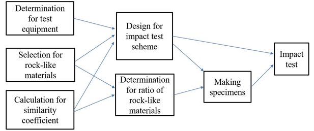
It can be seen from the figure that the determination for test equipment, selection for rock-like materials and calculation for similarity coefficient are the basis and premise of this test. The design for impact test scheme must be based on these three factors, and the determination for ratio of rock-like materials can only be carried out after the model materials are selected and the similarity coefficient is calculated. Then according to the designed impact test scheme and the ratio of rock-like materials, the specimens required in test are made and finally the impact test is carried out.
3. Test program
3.1. Test purpose and method
In underground engineering, the strain rate of rock mass caused by explosion impact is between 101-103s-1. However, the strain rate produced by traditional static and quasi-static loading test equipment is only within 1 s-1, and the rapid loading function can produce the loading rate within 10 s-1 strain rate range, which cannot simulate the strain rate during explosion and impact. In order to study the dynamic properties of rock in this high strain rate range, the Split Hopkinson Pressure Bar (SHPB) test system is currently most widely used in experiments, which can apply dynamic loads in the range of 102-104s-1 strain rate to rock specimens [6-10]. Therefore, SHPB was used in this test to conduct impact compression test on specimens.
In view of the fact that the current SHPB cannot meet the impact compression test of rocks under ultra-high confining pressure, this test seeks to explore the dynamic mechanical properties of rocks under high in-situ stress in the deep by replacing rocks with similar materials.
Similar materials are mainly used in similar physical model tests, and play a key role in model test results [11-15]. With the similar physical model test gradually becoming the main means to study large-scale geotechnical engineering problems in various fields of geotechnical engineering [16, 17], more and more attention has been paid to the development of model similar materials and their mechanical properties. According to the study of model similar materials by Luofeng [18], Consoli [19], YuanPu [20], etc., it can be seen that cemented sand similar materials (its unit weight is 18.2 kN/m3) can simulate sandstone very well and be successfully applied to large-scale geomechanical model test. Therefore, cemented sand as similar materials were used in this study to replace rocks.
In order to characterize the state of high in-situ stress in which the rock is located, an active confining pressure loading device which can provide stress in two directions of and () was used to constrain the specimen.
3.2. Specimen preparation
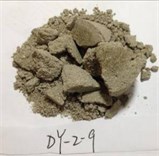
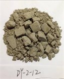
Cemented sand is one kind of artificial material, which made with quartz sand as aggregate, gypsum powder as regulator and cement as binder [19]. The type of ordinary portland cement used in this study is P.O 42.5, and the size of quartz sand is required to be no more than 1.18 mm.
According to the reference [21], the size of the specimen used for impact compression test was designed as ∅50×25 mm. In order to reduce the test error caused by inertia effect and friction effect, the non-parallelism of two end surfaces of each specimen was controlled within 0.05mm and the surface flatness within 0.03 mm.
According to the similarity theorem, the design strength of similar materials is calculated according to the similarity coefficient and the strength of original rock (the ratio between the physical quantities of the prototype and the model, called the similarity coefficient, commonly expressed as C).From the sizes of engineering prototype and loading device [22], it can be calculated that the geometric similarity coefficient is 20; From the bulk density of cemented sand (18.2 kN/m3) and prototype rock mass (26 kN/m3), it can be calculated that the bulk density similarity coefficient is 1.42; and the stress similarity coefficient () is 28.4. Therefore, according to the stress similarity coefficient of 28.4 and the original rock strength of 135 MPa, it is concluded that the strength of similar cemented sand materials used in this test should be 4.75 mPa, and the corresponding ratio is: sand: cement: gypsum: water = 1:0.095:0.05:0.1.
3.3. Test apparatus
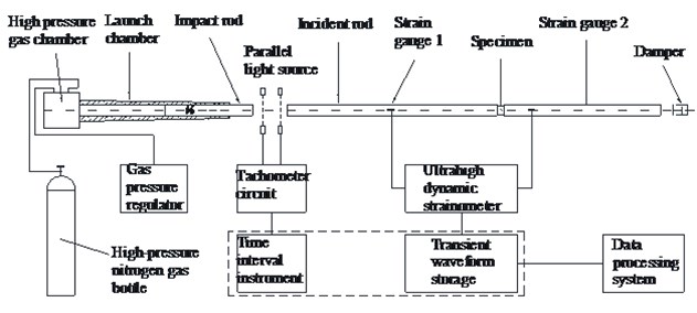
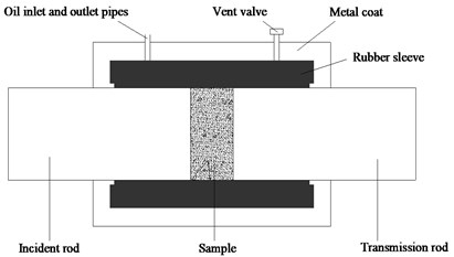
In this test, the steel SHPB test device and the active confining pressure loading device (as shown in Fig. 2 and Fig. 3) were used to carry out uniaxial and triaxial impact compression tests on cemented sand specimens.
Wherein the lengths of the impact bar, incident bar and transmission bar were respectively 600 mm, 2,400 mm, and 1,200 mm, while the elastic modulus, density, and elastic wave velocity were 210 GPa, 7,800 kg/m3, and 5,190 m/s. The basic principle of SHPB can be summed up as measuring data and deducing relation between stress and strain. The main test process of SHPB is that the incident wave and reflected wave from the incident bar and the transmitted pulse from the transmitted bar were measured with the aid of the strain gauge firstly, and then the two-wave method or three-wave method formula (obtained from the one-dimensional stress wave theory) was used to process the data to obtain the stress-strain relationship of the specimen [23]. Due to low wave impedance of the cemented sand, the semiconductor strain gauge technique was used to measure weak transmission signals, but a resistance strain gauge was still used for the incident bar. Paper [24] was used as a pulse shaper and was pasted on the end of the incident bar to improve the loading waveform of the incident pulse and prolong the rising time of the incident pulse.
The principle of the active confining pressure loading device is that the liquid was pressurized through the manual booster pump, and then the liquid transferred the pressure to the sealing ring which was used to wrap test specimen, and finally the sealing ring applied the pressure to the cemented sand specimen. Because of its simple principle, exquisite structure and convenient operation, it is in widespread used as a device for simulating in-situ stress in the laboratory.
Fig. 2SHPB device: a) schematic, b) pressure bar, c) data processing system
a)
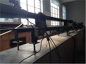
b)
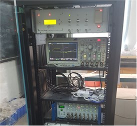
c)
Fig. 3Active confining pressure device: a) diagram, b) actual picture
a)
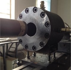
b)
3.4. Test design
The buried depth and bulk density of the simulated reserved rock mass in the model test for deep rock mass blasting were 750 m and 26 KN/m3 respectively. The horizontal lateral pressure coefficient of the crustal stress was 1.5, while the stress similarity coefficient was 28.4. In addition: based on the fact that vertical stress , 19.5 MPa was obtained; based on average horizontal stress 1.5, 29.25 MPa was obtained; based on mean stress , 24.375 MPa was obtained, and so the simulated confining value was 0.858 MPa. Therefore, five confining stress values were calculated to be 0.86 MPa, 1 MPa, 1.15 MPa, 1.3 MPa, and 1.45 MPa for the purposes of this test design. For other designed parameters, see Table 1.
Table 1SHPB compression test design
Impact air pressure / MPa | Confining pressure / MPa | Number of tested samples |
0.15, 0.2, 0.25, 0.3 | 0 | 16 |
0.9 | 0.86, 1.15, 1.3, 1.45 | 16 |
0.3, 0.5, 0.7, 0.9 | 1 | 16 |
4. Results and discussion
4.1. Analysis of dynamic compression tests of cemented sand under uniaxial pressure state
Fig. 4 shows the stress-strain curves of cemented sand at four different strain rates under a uniaxial state. Fig. 5 shows the failure modes corresponding to the four strain rates.
Fig. 4Stress-strain curves of cemented sand at different experimental strain rates
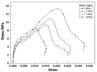
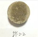
Fig. 5Failure modes of cemented sand at different experimental strain rates: a) ε˙= 89/s, b) ε˙ = 115/s, c) ε˙ = 118/s, d) ε˙ = 143/s. Note: ε˙ – strain rates
a)

b)
c)
d)
4.1.1. Mechanical analysis of stress-strain curves
As shown in Fig. 4, the dynamic compression stress-strain curves of the cemented sand underwent generally similar changes at different test strain rates, which could be roughly divided into four stages; i.e. the elastic, compacting, yielding, and failure stages. Firstly, since the internal micropores of the cemented sand were not closed under high-speed impact load, the dynamic stress-strain directly forced the entry into the elastic stage, the curve was linear, and the stress and strain existed in direct proportion to each other. However, the micropores of the cemented sand compacted when the load rose, so the curves were would be subject to “strain softening.” As the stress increased, the rate of strain growth increased. The sample then entered the yielding stage, after which the stress-strain curve began to bend downward; namely, the slope of the curve decreased with the increase of stress, and the local internal failures within the specimen gradually grew before reaching the peak point. Ultimately, macroscopic failures formed due to a coalescence of internal cracks within the cemented sand, the specimen failed to bear the load and entered the failure stage.
4.1.2. Morphological analysis of dynamic fracture failure
In terms of the morphology of fracture failure morphology, as the strain rate increased, the sizes of the specimen fragments significantly reduced, while the number of fragments was greatly increased, showing a strong strain rate correlation. As shown in Fig. 5(b), at a low strain rate, the axial direction of the cemented sand specimen was divided by three main cracks intersected at one point, and the cracks grew in a direction perpendicular to the tensile strain; the lateral and internal sides of the specimen formed fracture surfaces parallel to the length direction, and there were no scratches among the fracture surfaces. This failure is also known as the radial tensile failure mode, in which tensile failure travels along the transverse direction due to the Poisson effect [25]. However, under high strain rates, it formed a crushing failure due to serious fractures such as those shown in Fig. 5(d).
4.2. Analysis of dynamic compression tests of cemented sand under confining pressure
Fig. 6 shows the stress-strain curves of the cemented sand at the same strain rate (260 ± 5/s) under different confining pressures. Fig. 7 shows failure modes corresponding to five strain rates.
Fig. 6Stress-strain curves of cemented sand under different confining pressures
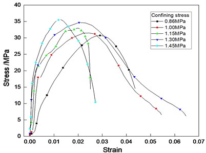
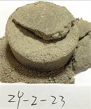
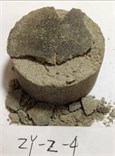
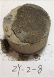
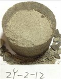
Fig. 7Failure modes of cemented sand under different confining pressures: a) CP= 0.86 MPa, b) CP= 1.0 MPa, c) CP= 1.15 MPa, d) CP= 1.3 MPa, e) CP= 1.45 MPa. Note: CP – confining pressures
a)
b)
c)
d)
e)
4.2.1. Mechanical analysis of stress-strain curves
As shown in Fig. 6, the dynamic stress-strain curve of the artificial cemented sand material placed under confining pressure could be divided into three stages; i.e. the elastic, yielding, and failure stages. Using the microstructural characteristics of the material, a comparative analysis was made on the dynamic stress-strain curve and failure morphology of the cemented sand specimens, concluding that the micropores within the cemented sand specimen were compressed under the confining pressure. Thus, the stress-strain curve became longer in the elastic stage, and the slope of straight part of the curve became higher. When the stress-strain curve rose to about 50 % of the peak stress (> 50 % under high confining pressure and < 50 % under low confining pressure), the stress-strain curve may deviate from this straight line, and enter the yielding stage. When the dynamic load increased continuously and the peak value was surpassed, the curve entered the failure stage.
4.2.2. Morphological analysis of dynamic fracture failure
As shown in Fig. 7, a relatively obvious spallation occurred at the head of the cemented sand specimen when it was placed under confining pressure, and a tapered cavity was formed, but no crushing ensued. As the stress of the confining pressure increased, the specimen tended to remain complete. This indicated that the active confining pressure loading device limited the radial growth of the specimen, so that the energy transmitted to the specimen by the impact load was dissipated and reduced, and the reflection of the stress wave was enhanced. The specimen was thus subject to reflection tensile failure, specifically to axial tensile failure.
4.3. The effects of confining pressure on the dynamic mechanical properties of cemented sand
Table 2 primarily lists the testing parameters and dynamic mechanical properties of the artificially produced cemented sand under different degrees of confining pressure when the strain rate of cemented sand is 260 ± 5/s.
Table 2The testing parameters and dynamic mechanical properties of cemented sand
Numbering | (×) / mm×mm | / m∙s-1 | / MPa | / s-1 | / MPa | / GPa | SEA / J∙cm-3 | ||
DY-2-12 | 50×25.61 | 4.88 | 0 | 143.5 | 13.5 | 0.02073 | 0.618 | 1 | 0.272 |
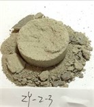
ZY-2-3 | 50×26.1 | 9.29 | 0.86 | 255.2 | 30.8 | 0.02907 | 1.303 | 2.28 | 0.752 |
ZY-2-23 | 50×25.38 | 9.31 | 1 | 257.2 | 31.8 | 0.02448 | 2.376 | 2.36 | 0.716 |
ZY-2-4 | 50×25.94 | 9.28 | 1.15 | 259.9 | 33.0 | 0.01989 | 2.318 | 2.44 | 0.678 |
ZY-2-8 | 50×25.06 | 9.30 | 1.3 | 263.5 | 34.7 | 0.02036 | 3.262 | 2.57 | 0.564 |
ZY-2-12 | 50×25.15 | 9.32 | 1.45 | 264.4 | 35.6 | 0.01276 | 4.559 | 2.64 | 0.511 |
Note: × shows the diameter × the thickness of the specimen; is the velocity of the impact bar; isthe stress value of confining pressure; is the strain rate; is the peak stress; is the peak strain; is the elastic modulus; is the dynamic compressive strength growth factor, i.e., the ratio of triaxial dynamic compressive strength to the uniaxial dynamic compressive strength; and SEA is the specific energy absorption value, i.e. the energy absorbed per unit volume of the specimen | |||||||||
4.3.1. The relationship between the , , and of cemented sand
The dynamic compressive strength growth factor η is the ratio of the dynamic compressive strength under confining pressure () to the conventional dynamic compressive strength ().
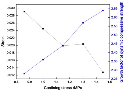
Fig. 8 shows the relationship between , , and of the cemented sand specimen when the strain rate is 260±5/s.
As shown in Fig. 8, as the stress of confining pressure increased, the peak strain of the cemented sand specimen gradually decreased, while the dynamic compressive strength growth factor continuously increased.
According to the stress-strain curve and the morphology of the dynamic fracture failure (Fig. 6 and 7) under confining pressure, it could be seen that the initial pores of the cemented sand specimen were compacted under the stress of confining pressure, and the microstructure of the material was changed, leading to increased brittleness. The dynamic failure tended to be complete, further showing that the constraint of confining pressure may improve the failure resistance of artificial cemented sand.
Fig. 8The relationship between the εp, η, and Cp of cemented sand under a constant strain rate
4.3.2. The relationship of and of cemented sand
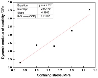
Since the stress-strain curve of the cemented sand artificial material is nonlinear and changes more significantly with increasing stress (strain), the elastic modulus is correlated with the selected reference points. Many parameters can be described, such as initial modulus , secant modulus , tangent modulus , and mixed modulus [26]. This study uses the mixed modulus; i.e., the slope of the line between the two points on the rising section of the curve where the compressive strength is respectively 20 % and 80 % of peak intensity.
Fig. 9 shows the relationship between and of the cemented sand specimen when the strain rate was 260 ± 5/s.
As shown in Fig. 9, as the stress of confining pressure increased, the dynamic elastic modulus of the cemented sand increased linearly with the effect of increased confining pressure. The following equation was obtained after performing a linear fit of the data points:
Fig. 9The relationship of E and Cp of cemented sand under a constant strain rate
4.3.3. The relationship between SEA and of cemented sand
In order to establish the relationship between the energy dissipation occurring within the rock failure process and the confining pressure, specific energy absorption (SEA) was defined as the energy absorbed per unit volume of the cemented sand specimen during the impact compression process. An energy analysis was performed on the impact compression process, showing the following:
where, , , and were respectively the incident stress wave energy, reflected stress wave energy, and transmitted stress wave energy; , , and were respectively the cross-sectional area of the input bar, the acoustic wave transmission speed within the bar, and the elastic modulus of the input bar; and , , and were the stress time histories of the incident stress wave, reflected stress wave, and transmitted stress wave respectively.
Assuming that the energy loss at the cross section of the specimen, the input bar, and the transmission bar was negligible, the energy absorbed by the cemented sand specimen and the specific energy absorption SEA could be obtained through the following formula:
where was the volume of the cemented sand specimens.
Fig. 10 shows the relationship between the SEA and of the cemented sand specimen when the strain rate was 260 ± 5/s.
Fig. 10The relationship between the SEA and Cp of cemented sand under a constant strain rate
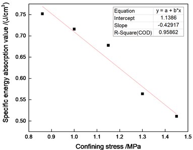
Given the approximate speed of the impact bar under different confining pressures, the energy of the incident wave could be considered to also be an approximation. It can therefore be concluded that, under the estimated energy of the incident wave’s action, the cemented sand specimen had a higher specific energy absorption value at a low confining pressure than at a high confining pressure, because the higher the confining pressure, the greater the cemented sand specimen’s reaction force for lateral deformation would become under its impact load. This would also be directly proportional with greater limitations on crack development, and reduced energy dissipation, indicating that the specific energy absorption of the specimen had been lowered in macroscopic terms. The two parameters formed a linear relation after the data points were fit:
5. Conclusions
According to uniaxial and triaxial impact compression tests on cemented sand specimens, it is found that confining pressure has a great influence on its dynamic compression performance, mainly including:
1) The dynamic compression deformation and failure of the specimen under confining pressure has only elastic stage, yield stage and failure stage, which reduces the compaction stage compared with that under unconfining pressure.
2) The dynamic failure mode of the specimen changed from radial tension to axial tension under uniaxial impact, and the factors leading to the failure of the specimen changed from relatively concentrated main cracks to relatively uniform microcracks or damage cracks.
3) Under the condition of the same or similar strain rate, the dynamic compressive strength and dynamic elastic modulus of the specimens increase with the increase of confining pressure.
4) In addition, confining pressure also has a significant effect on the specific energy absorption of cemented sand specimens. When the energy of incident wave is the same, the specific energy absorption value of cemented sand specimens decrease with the increase of confining pressure.
According to the above conclusions, the dynamic mechanical properties of deep rock under the double action of blasting load and in-situ stress will be inevitably changed greatly, which will affect the design of blasting parameters of deep rock blasting excavation. The specific performance is as follows: the action of high in-situ stress will improve the rock’s anti-damage ability, resulting in the increase of its dynamic compressive strength, which leads to the phenomenon of difficult explosion. Therefore, in the deep rock mass, the blasting method is used to excavate the tunnel, which means that it needs to increase the amount of explosive according to the increase of in-situ stress; because of the change of dynamic elastic modulus, it can’t be directly used to calculate the attenuation law of explosion stress wave in the deep rock mass blasting; in-situ stress will restrict the generation and propagation of rock cracks, so that the macro cracks after blasting will be reduced, and more relatively uniform micro cracks or damage cracks will be generated instead, in addition, in-situ stress will also enhance the reflection of stress wave, so the proportion of circumferential cracks will inevitably increase, which will further lead to the change of blasting crack propagation mechanism of deep rock mass; under the same charge, the larger the in-situ stress is, the less the energy dissipated per unit volume of rock is, and the slower the attenuation of shock wave is. Therefore, the stress wave intensity in the actual deep rock blasting will be much higher than that calculated by the conventional attenuation formula of shock wave propagation.
In this paper, the analysis of dynamic mechanical properties of rock in deep rock blasting is based on similar materials to rocks and impact tests. Therefore, the conclusions are limited and another study need to focus on the properties of rock under the conditions of in-situ stress and blasting.
References
-
Shengcai Z. Resource exploitation and underground engineering under high stress in deep. 175th Xiangshan Conference Advance in Earthscience, Vol. 17, Issue 2, 2002, p. 295-298.
-
Vogel M., Rast H. P. AlpTransit – safety in construction as a challenge: health and safety aspects in very deep tunnel construction. Tunnelling and Underground Space Technology, Vol. 15, Issue 4, 2000, p. 481-484.
-
Junzhong L., Jinyu X., Dehui Z. Experimental study of shock compression properties of underground engineering rock under active confining pressure. Chinese Journal of Rock Mechanics and Engineering, Vol. 30, Issue 2, 2011, p. 4104-4109.
-
Fengqiang G., Xibing L., Xiling L. Tests for sandstone mechanical properties and failure model under triaxial SHPB loading. Journal of Vibration and Shock, Vol. 31, Issue 8, 2012, p. 29-32.
-
Jiefang J., Xibing L., Zhiqiang Y. The Effects of axial compression will and confining pressure on energy dissipation of sandstone under cyclic impact loads. Rock and Soil Mechanics, Vol. 34, Issue 11, 2013, p. 3096-3102.
-
Xiaowang S., Kai Z., Yongchi L. A study of strain-rate effect and fiber reinforcement effect on dynamic behavior of steel fiber-reinforced concrete. Construction and Building Materials, Vol. 158, 2018, p. 657-669.
-
Md Fazlay R., Vijaya C., Yong K. Dynamic constitutive response of novel auxetic Kevlar®/epoxy composites. Composite Structures, Vol. 195, 2018, p. 1-13.
-
Zejian X., Yu L., Zhongyue S. On shear failure behaviors of an armor steel over a large range of strain rates. International Journal of Impact Engineering, Vol. 118, 2018, p. 24-38.
-
Kumar M. K., Naik N. K. Prediction of mechanical behavior of composites under high strain rate tensile loading. Mechanics Research Communications, Vol. 90, 2018, p. 1-7.
-
Mario C., Chongchen X., Javier N. Reactive melt infiltration as synthesis route for enhanced SiC/CoSi2 composite materials for advanced armor systems. Ceramics International, Vol. 44, Issue 11, 2018, p. 13182-13190.
-
Qiangyong Z., Shucai L., Xiaohong G. Research and development of new types of cementitious geotechnical substitute material for iron crystal sand and its applications. Rock and Soil Mechanics, Vol. 29, Issue 8, 2008, p. 2126-2130.
-
Tianbin L., Xiangfeng L., Lubo M. Physical simulation study of artificial materials for rockburst. Chinese Journal of Rock Mechanics and Engineering, Vol. 30, Issue 1, 2011, p. 2610-2616.
-
Fangping M., Zhongkui W., Guangfu L. NIOS model material and its use in geo-mechanical similarity model testing. Journal of Hydroelectric Engineering Power, Vol. 23, Issue 1, 2004, p. 48-52.
-
Wensheng X., Yingnian X., Yuanhan W. Experimental study on simulation materials for rockburst. Chinese Journal of Rock Mechanics and Engineering, Vol. 19, Issue 1, 2000, p. 873-877.
-
Xiansong H., Hongqi M., Lin L. Study of testing methods of geomechanical models and temperature analogous model materials. Chinese Journal of Rock Mechanics and Engineering, Vol. 28, Issue 5, 2009, p. 980-985.
-
Anmin C., Jincai G., Jun S. Application study on geomechanical model experiment techniques. Chinese Journal of Rock Mechanics and Engineering, Vol. 23, Issue 22, 2004, p. 3785-3789.
-
Qiangyong Z., Shucai L., Yong L. New Methods, New Technologies, and Engineering Applications of Underground Engineering Model Tests. Science Press, Beijing, 2012.
-
Feng L., Bensheng Y., Binbin H. Mechanical properties of similar material under uniaxial compression and the strength error sources. Journal of Mining and Safety Engineering, Vol. 30, Issue 1, 2013, p. 93-99.
-
Consoli N.C., Cruz R.C., Floss M.F. Variable controlling strength of artificially cemented sand: influence of curing time. Journal of Materials in Civil Engineering, Vol. 23, Issue 5, 2011, p. 692-696.
-
Pu Y., Ying X. Influence of curing time on compressive properties of cemented sand similar materials. Journal of Vibration and Shock, Vol. 34, Issue 13, 2015, p. 200-204.
-
Pankow M., Attard C.,Waas A.M. Specimen size and shape effect in split Hopkinson pressure bar testing. The Journal of Strain Analysis for Engineering Design, Vol. 44, Issue 8, 2009, p. 689-698.
-
Ying, X., Jinjin, G. Energy analysis on dynamic fragmentation degree of cemented sand specimens under confining pressure. Shock and Vibration, Vol. 2019, 2019, p. 5893957.
-
Li S., Shisheng H. Two wave and three wave method in SHPB data processing. Explosion and Shock Waves, Vol. 25, Issue 4, 2005, p. 368-373.
-
Wu X.J., Gorham D.A. Stress equilibrium in the split Hopkinson pressure bar test. Le Journal de Physique IV, Vol. 7, Issue C3, 1997, p. 91-96.
-
Fengqiang G. Experimental Study of Rock Mechanical Properties under Coupled Static-Dynamic Loads and Dynamic Strength Criterion. Central South University, Changsha, 2010.
-
Yi Z. Study of Dynamic Mechanical Properties of Carbon Fiber Reinforced Concrete. Air Force Engineering University, Xi’an, 2009.
About this article

We extend our gratitude to the National Natural Science Foundation, China (51374012), and to the Anhui Province Science and Technology Project, China (1501041123). Their support is gratefully acknowledged.
