Abstract
Strength and deformability characteristics of rock with pre-existing fissure are governed by cracking behavior. To further research the effects of pre-existing fissures on the mechanical properties and crack coalescence process under staged unloading conditions, a series of uniaxial compression tests were carried out. In this study, cement, fine sand, and water were used to fabricate a kind of brittle rock-like material rectangular model specimen. The mechanical properties of rock-like material specimen used in this research were all in good agreement with the brittle rock materials. The pre-existing fissure was created by mica sheets and the unloading zone was created by pre-filling Polylactic acid (PLA) resin material during the molding processes the model specimen. And the staged unloading test was conducted based on polylactic acid’s hot-melt characteristics. In order to investigate the crack initiation, propagation and coalescence process, inclination angle of pre-existing fissure was set to change from 0° to 90°. The mechanism of crack propagation and coalescence under photographic monitoring was discussed. And these experimental results indicate that the failure modes in the zone above unloading zone mainly consist of four modes: separation failure, shear-slip failure, mixed shear-separation failure and compression-shear failure. The experimental results are also expected to increase the understanding of the strength failure behavior and the cracking mechanism of rock under staged unloading.
Highlights
- The pre-existing fissure was created by mica sheets and the unloading zone was created by pre-filling Polylactic acid (PLA) resin material during the molding processes the model specimen.
- There are four failure modes: separation failure, shear-slip failure, mixed shear-separation failure and compression-shear failure.
- The test use hot melt method to achieve digging unloading.
1. Introduction
Study on mechanical behaviors of rock material containing different pre-existing flaws (such as fissures, holes) has been a significant project in current research [1-4]. It is of great theoretical value and practical significance to study the mechanical behavior of cracked rock mass and patterns of crack initiation, propagation and coalescence. In recent years, many scholars have studied the damage characteristics of fractured rock mass under loading and unloading conditions.
Nowadays, many research results have been obtained in zones of crack propagation law, failure mode and mechanical properties of fractured rock mass under loading conditions [5-8]. Yang Shengqi et al. [9, 10] conducted uniaxial or triaxial tests on intact rocks and rocks containing single crack, double cracks, and multiple cracks respectively. Besides, they investigated the failure characteristics and mechanical characteristics of brittle specimens containing pre-existing fracture. In addition, Jiang Mingjing et al. [11, 12] studied the crack evolution law and the propagated coalescence law of fractured rock mass through numerical simulations. As the mechanical properties of rock masses under unloading are increasingly valued, more and more scholars have begun to study the failure modes and mechanical properties of fractured rock materials under unloading conditions. Li Jianlin [13, 14] made further study on the strength, deformation failure and size effect of the unloading rock mass, but he did not involve the destruction of the rock mass and the evolution of the fracture under the unloading conditions. To further research the effects of unloading deformation failure, strength and fracture evolution of fractured rock masses, Huang Da et al. [15] studied the physics model tests of double pre-existing fissures under two kinds of unloading stress paths. A comparative study on single and double pre-existing in crack marbles has been carried out by Song Yanqi [16, 17]. The comparisons analyzed the strength, deformation and fracture propagation rules and discussed the mechanical properties of fractured rocks under loading and unloading conditions. Thus, in rock engineering projects the mechanism of crack coalescence of pre-existing fissure plays an important role in controlling the stabilities of slopes, foundation engineering and tunnels [18-21]. However, most of the previous unloading test studies are carried out by unloading the confining pressure in a biaxial or triaxial test, the staged unloading of underground works such as excavation of chamber is a process of unloading from interior of the surrounding rock. For the studies on staged unloading, the effect of staged unloading on surrounding rock has only been analyzed using numerical simulation methods [22-24]. Few scholars have involved in the crack propagation of fractured rock mass under staged unloading through experimental study.
To better understand the failure mechanical behavior of specimens containing pre-existing fissure and pre-filling excavation station, uniaxial compression tests were carried out on rock-like material in this research. On the basis of these test data, we analyze the strength and deformation behavior, micro-cracks propagation process at the tip of fissure and investigate the relationship between inclination angle and crack coalescence process of rock-like material under staged unloading conditions.
2. Experimental material and procedure
2.1. Specimen preparation
According to numerous laboratory rock-like material tests, we fabricated the model specimen by compounding C42.5 cement, fine sand, and water at a mass ratio of 2:2:1 by volume. The sand had been sieved through a 1.05 mm hole size before modeling. Joints are created by inserting mica sheets (0.3 mm thick and 40 mm long) into the fresh cement mortar paste at the experimental joint location. In this paper, the word “fissure” represents the pre-existing crack, and the word “crack” indicates the secondary crack. The mold had been left aside for about 24 h before the fissured specimen was removed from the mold. Geometry of crack of the tested rock-like material specimens can be seen in Fig. 1. The geometry of crack is described as follows: is the pre-existing fissure dip angle; d is the height of staged unloading zone (15 mm); is the length of the staged unloading zone (70 mm); is the distance between the left tip of the pre-existing fissure and the top of the unloading zone (15 mm). In the design, A5, B5, C5, D5 and E5 are the specimens whose was set to be 0°, 22.5°, 45°, 67.5° and 90° respectively. All of specimens are under a normal stress of 16.7 MPa and the physical and mechanical properties of rock-like materials have been listed in Table 1.
Fig. 1Distribution graph of pre-existing fissure and unloading zone in specimen
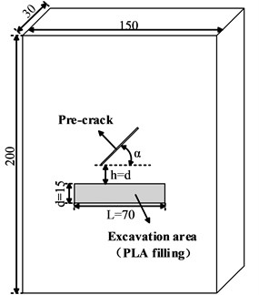
Table 1Mechanical parameters of rock-like materials
Material density / (kg/m3) | Elastic modulus / GPa | Uniaxial compression strength / MPa | Tensile strength / MPa | Poisson’s ratio |
2011 | 1.68 | 21.19 | 1.62 | 0.26 |
2.2. Excavation zone filling materials
The choice of filling material for the unloading zone was based on principles that the elastic modulus of the selected material is similar to the specimen. Furthermore, the uniaxial compressive strength is higher, and that the staged unloading process is easy to realize. Laboratory tests were conducted on polylactic acid (PLA) resin material specimens. And the physical and mechanical properties of polylactic acid resin material are shown in Table 2.
Table 2Mechanical parameters of polylactic acid (PLA)
Material density / (kg/m3) | Elastic modulus / GPa | Uniaxial compression strength / MPa | Tensile strength / MPa |
1235 | 1.52 | 27.87 | 8.65 |
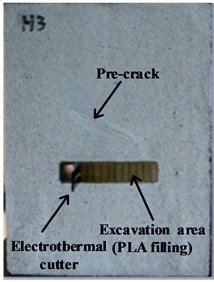
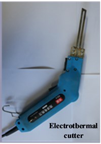
Combining with Table 1 and Table 2, it can be seen that the polylactic acid resin material meets the requirements in mechanical properties. The melting point of polylactide resin is about 180°C. Yin Tubing [25] comparatively analyzed the change of rock mechanics properties of sandstone under high temperature. Within 200 °C, the mechanical properties of rock will not change significantly. Therefore, the test use hot melt method to achieve digging unloading. The thermal conductivity of polylactic acid resin is 0.025 W/(m·K), which is very poor. So, when one part of the polylactic acid resin block was thermally melted by an electric thermal cutter, it exerted little impact on the mechanical properties of the remaining unmelted polylactic acid resin block. The polylactic acid resin material was used to pre-fill the excavation zone to meet mechanical performance requirements and ensure the smooth progress of the staged unloading.
2.3. Testing equipment and procedure
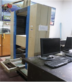
All of the uniaxial compression and the staged unloading tests were carried out on RYL-600 rock shear rheometer test machine, which provides a constant load in the vertical direction, as shown in Fig. 2.
Fig. 2RYL-600 rock shear rheometer test machine
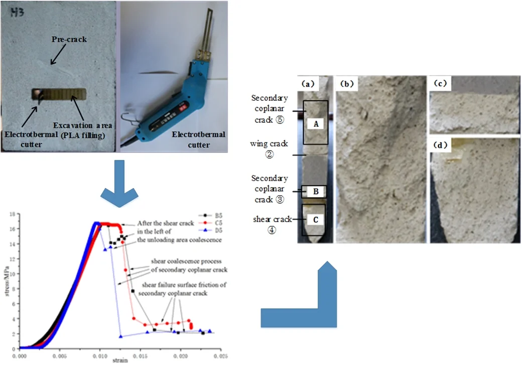
In order to investigate the effect of fissure dip angle on the failure mode of specimens under staged unloading conditions, staged unloading tests were carried out for each set of specimens under a same normal load of 75 KN (16.7 MPa). All the tests were conducted under force-controlled conditions with a rate of 200 N/s before excavation. After the normal load being loaded to the design value, staged unloading operation was performed after the stabilization of normal deformation to ensure that the normal stress of the pre-existing fissure specimen reaches a steady state. Staged unloading was proceeded using hot-melt method. Use of the electric cutting knife made polylactic acid resin unloading zone melt gradually. A detailed description of the unloading operation and electric cutting tool is given in Fig. 3. The unloading test is divided into 14 unloading steps, each of which is 5 mm in length. Moreover, to ensure the stress state of specimen reaches equilibrium, a new step of staged unloading will not be performed until the normal deformation was stabilized. Besides, if an unstable crack growth phenomenon was found during staged unloading, the unloading process would stop immediately.
Fig. 3Step excavation unloading operation diagram and the tool
a)
b)
3. Crack propagation and failure process
3.1. The unloading failure process of horizontal and vertical fissure specimens
Table 3 shows the crack propagation patterns of pre-existing fissure specimens A5 and E5 under staged unloading. When specimen A5 was in the staged unloading step 4, micro crack 1) on the left tip of pre-existing fissure started to propagate and micro cracks 2) on the middle-left tip of pre-existing fissure connected to the excavation surface; during the subsequent staged unloading, branch crack 4) was generated in the crack 1) and propagate along the normal stress at the unloading progresses. After the staged unloading in step 10 was completed, crack 5) penetrated the bottom of the specimen in the left zone of the unloading zone, followed by crack 4) propagation. The crack 4) propagate direction suddenly changed and quickly penetrated the upper left corner of specimen. Meanwhile, crack on the right-hand of staged unloading result in crack 6) and 7), subsequently crack 6) penetrated the bottom of the specimen, and crack 7) connected pre-existing fissure and unloading zone, which caused the specimen failure.
Table 3Crack propagation and failure mode of A5 and E5 under staged unloading
Specimen | Crack propagation and failure modes | Schematic diagram |
A5 | 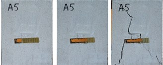 | 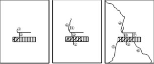 |
E5 | 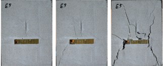 | 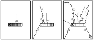 |
When specimen E5 was unloaded in step 2, micro cracks 1) were initiated at the lower tip of pre-existing fissure; after the completion of staged unloading in step 3, micro cracks 2) on the right end of staged unloading zone were propagated along the direction of normal stress. The crack at the left end of staged unloading zone produced crack 3) and it penetrated through the bottom of specimen. Crack 4) propagated in the far field of pre-existing fissure and propagated to the middle of pre-existing fissure, later on it penetrated through the upper left corner of the specimen. Subsequently, cracks 5), 6) and 7) were generated away from the pre-existing fissures. There was no pre-existing fissure coalescence when specimen was eventually destroyed.
3.2. The unloading failure process of inclined fissure specimens
Table 4 shows the crack propagation and failure process pattern diagrams of different angle fissure specimens B5, C5 and D5 under staged unloading processes. After specimen B5 was unloaded in step 5, there were wing cracks produced at the left tip and the middle of pre-existing fissure. The wing crack 1), which was perpendicular to pre-existing fissure propagated to the unloading zone, continued to propagate which caused the initiation of crack 3). Followed step 6, wing cracks 2) first spread along the normal direction. Then it was compacted together with cracks 3), and cracks 4) initiated below the left end of the unloading zone, later it penetrated the lower left corner of the specimen. The lower left corner coalescence while the right tip simultaneously initiated wing crack 5). After crack 5) stopped propagating, crack 6) in the middle of pre-existing fissure propagated to the staged unloading zone, and the secondary co-planar crack 7) which initiated at the right tip propagated rapidly to cause the overall failure of specimen.
Table 4Crack propagation and failure mode of B5, C5 and C5 under staged unloading
Specimen | Crack propagation and failure modes | Schematic diagram |
B5 | 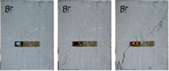 | 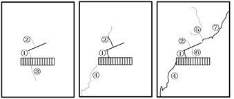 |
C5 | 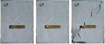 | 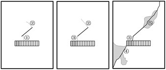 |
D5 | 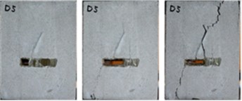 | 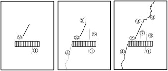 |
After the C5 specimen was unloaded in the step 3, two wing cracks were generated at near the left tip and the right tip of the pre-existing fissure respectively. When in the unloading step 4, crack 1) was gradually compacting, wing cracks 2) continued to propagate perpendicular to pre-existing fissure and crack 3) was newly generated at the left tip of pre-existing fissure then connected the unloading zone. In the step 4 of unloading, the newly generated crack 4) was observed to have unstable propagation, so the unloading was stopped immediately. The crack continued to propagate and penetrated through the lower left corner of specimen. At this time, crack 2) was compacted. The secondary coplanar crack 5) was generated at the right tip of pre-existing fissure and rapidly propagated to the upper right corner of specimen. Subsequently the specimen was destroyed as a whole.
For the specimen D5, the crack 1) appeared during loading process. During the unloading step 3, the secondary coplanar crack 2) on the left tip of pre-existing fissure propagated to the unloading zone. In the unloading step 8, crack 3) at the right tip of pre-existing fissure propagated in the direction of normal stress, and crack 4) at the left end of the unloading zone penetrated the bottom of specimen. Subsequently, crack 6) in the right tip of specimen was generated and quickly penetrated through the top of specimen to cause the overall failure of the specimen. Meanwhile, crack 7) connected to the unloading zone, which appeared in the middle of pre-existing fissure.
To sum up, the crack initiation, propagation and coalescence of the tilted fissure specimen under staged unloading gradually changed with the staged unloading. The destruction process is extremely complicated. The following points are mainly involved:
(1) The tensile cracks were only observed in specimens with inclinations of 22.5°. The initiation and propagation of wing cracks were found at the right tip of pre-existing fissure of specimens with inclinations of 45° and 67.5°.
(2) The fissure tip tensile coalescence mode was the only failure mode of horizontal and vertical fracture specimens in the staged unloading test, and the fissure tip had a rapid rate of tension and coalescence.
(3) In the staged unloading test of horizontal specimen, separation failure mode was the only failure mode of the zone above unloading zone, and the separation parts were caused by the tensile cracks in the middle of pre-existing fissure.
(4) When specimens with different inclination fissures were unloaded to the place where near the left tip of pre-existing fissure under the same normal stress, micro cracks of all inclination fissure specimens generated at the left tip of pre-existing fissure and propagated toward the excavation zone.
(5) Under the same normal stress, the oblique directions of failure surface of all inclination fissure specimens were consistent with the direction of the pre-existing fissure tilt direction.
4. Analysis of stress-strain curve
4.1. General characteristics and analysis of stress-strain curve under staged unloading
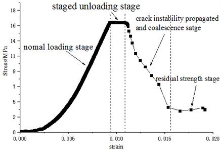
The whole stress-strain curves of different crack propagation failure modes under staged unloading are roughly the same. In order to investigate the characteristics and the significance of overall failure mode, the full stress-strain curve of inclined fissure specimen under staged unloading were analyzed, and the typical stress–strain curves of specimen D5 has been plotted in Fig. 4. As shown in Fig. 4, the stress-strain curves of the specimens with different inclination angles in the staged unloading can be divided into four stages: the normal loading stage, the staged unloading stage, the crack instability propagated and coalescence stage, and the residual strength stage. The slope of the curve of the normal loading zone before staged unloading shows no tendency to decrease. It is good for studying the crack initiation and propagation of the pre-existing fissure under the staged unloading conditions, which ensures that the micro-cracks do not generate before the unloading, and the whole sample remains the elastic deformation stage. In the staged unloading phase, although the normal stress remains unchanged, the normal strain will continue to increase with the staged unloading. This is mainly because of the decrease of cross-sectional zone which withstand normal pressure and the micro cracks initiation of the specimen.
Combined with the experimental process, it is found that the point where the slope of the curve changes from 0 to a negative value is the time when the micro-crack unstable accelerated propagation. Therefore, this point can be determined as the demarcation point between the unloading phase and the unstable propagation phase of cracks. In the failure stage, the failure modes of different specimen are different. The specimen A5 showed tensile coalescence at the fissure tip, so the graph shows a steeper drop in the stress-strain curve; however, specimens B5, C5, and D5 presented as secondary coplanar crack shear coalescence and the specimen E5 showed the overall compression-shear failure. After the coalescence, the whole specimen was divided into two parts which were caused by crack propagated along the pre-existing fissure direction. After the pre-existing fissure coalescence and destroyed, there is still a certain residual strength. This is due to the friction and bite of particles which on the failure surface at the later stage of specimen failure. This can be seen by observing shape of the particulates that have been destroyed on the surface of fracture.
Fig. 4Stress-strain curve of specimen with inclined fissure under staged unloading
4.2. Horizontal and vertical fissure specimen coalescence model and stress analysis
The failure mode of specimen A5 was the tensile coalescence at the fissure tip. During the staged unloading process of horizontal fissure specimen, many micro cracks generated in the middle of pre-existing fissure propagated and penetrated through the unloading zone. Besides, the micro cracks produced at the left tip of fissure tension and penetrated through the edge of specimen. Although micro cracks were produced at pre-existing fissure tip of specimen E5, the final failure did not occur through the coalescence of these micro cracks. During the staged unloading of vertical fissure specimen, the newly initiated micro crack under pre-existing fissure that generated by the tip undergo tension propagation and coalescence penetrated through the unloading zone, and the micro cracks that generated at the upper tip propagated through the edges of specimen.
Fig. 5Stress and strain curves of horizontal and vertical fissure specimens through mode
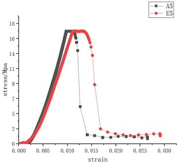
The stress-strain curves of the horizontal and vertical fissure specimen coalescence patterns are shown in Fig. 5. The stress-strain curves of specimens A5 and E5 are steeper in the descending zone, and the residual strength of A5 specimen is smaller than E5 after failure. The frictional force on the shear crack surface of the right zone under unloading zone provided the mainly residual strength of specimen A5, and the residual strength of E5 specimen is mainly provided by the supporting effect of the right zone of the unloading zone. From this stress-strain curve, it can be observed that the slope of the stress-strain curve after the unloading of E5 specimen has a significant negative increase, and there is a clear transition from the slow development of micro-cracks to the accelerated propagation before the overall failure.
In the staged unloading test of horizontal fissure specimen, the zone above the staged unloading zone of specimen is the separation failure, and the crack that causes separation and destruction in the zone is a tensile crack in the middle of pre-existing fissure. Two tensile cracks in the middle of pre-existing fissure penetrated through the unloading zone. Moreover, the tensile crack opening degree is large, and pre-existing fissures are also in the open state under tensile stress. In addition, the top of the staged unloading zone shows obvious displacement, and the separation part is in the falling state. Therefore, specimen E5 shows the overall compression-shear failure mode.
4.3. Inclined fissure specimen coalescence model and stress analysis
The micro cracks that are initiated toward pre-existing fissure tip can be classified into wing cracks, secondary coplanar cracks and secondary inclined cracks according to their developmental morphology. Depending on different stress characteristics of failure surface, the failure modes can be divided into tensile failure, shear failure and mixed shear failure. Combining the developmental morphology of micro cracks in the fissure tip, the mechanical properties of the failure surface and the stress-strain relationship at the moment of coalescence, the crack propagation and coalescence failure mechanisms in the test have been analyzed in detail.
The pre-existing fissure failure modes of specimens B5, C5, and D5 under a normal stress of 16.7 MPa were all secondary coplanar cracks shear coalescence. The stress-strain curves are shown in the Fig. 6. In the figure, the stress-strain curves of specimens B5, C5, and D5 all show a small peak after falling.
Fig. 6Stress-strain curve of shear coalescence process of secondary coplanar crack
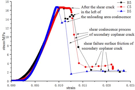
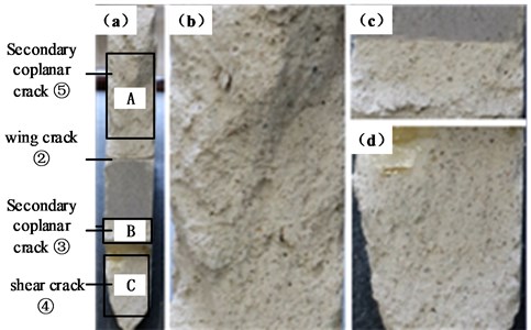
After observing the test video, it was found that with the progress of staged unloading, the stress concentration at the left end of the unloading zone initiated the shear crack and the shear crack penetrated the edge of specimen that result in the decrease of stress value. However, the overall failure of specimen did not occur and hence no obvious relative sliding happened in the surface of specimen. The final overall failure of specimen was caused by the formation of coalescence surface that was caused by a secondary coplanar crack newly generated at the pre-existing fissure tip. From the figure, it can be seen that after the shear crack at the left end of the unloading zone penetrated, the descending segment of the stress-strain curve is relatively steep, indicating that the secondary coplanar crack has a faster coalescence rate after initiation. The residual strength of this kind of failure mode is relatively large. This is because the shear surface was produced by shear stress, and when the relative sliding occurs under the action of compressive stress, the friction of granular part acts to increase the resistance. As a result, the pattern has a relatively large residual stress [8]. This conclusion can be verified by Fig. 7, in which the cracks cut through the failure surface have obvious signs of frictional failure.
Fig. 7Failure form of particle on failure surface of shear coalescence failure surface of C5 specimen: a) overall, b) A zone micrograph, c) B zone micrograph, C zone micrograph
5. Analysis of failure modes above the staged unloading zone
During the tunnel excavation process, arch collapse is one of the most common safety accidents. It occurs mostly in the case of joints or other unfavorable geology around the tunnel rock face near tunnel face. Therefore, it is of great significance to analyze the failure mode of the shelter between fracture and unloading zone.
In the staged unloading test of fissure specimen, depending on different characteristics of stress and damage, the failure modes in the zone above staged unloading zone can be divided into four modes, which consist of separation failure, shear-slip failure, mixed shear-slip and separation failure and compression-shear failure.
(1) Overall separation failure.
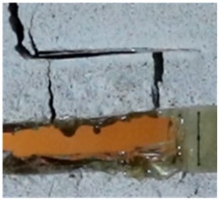
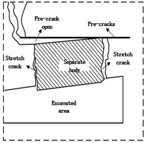
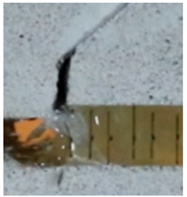
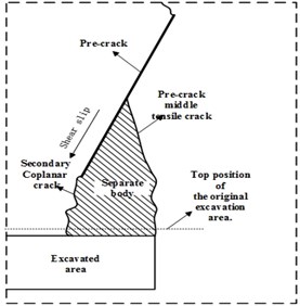
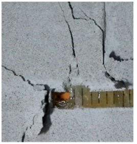
The failure mode of A5 and B5 specimens is overall separation failure. As an example, the failure mode of specimen A5 is shown in Fig. 8. Two cracks which generated at both ends of the pre-existing fissure penetrated the unloading zone. This led to separation between the entire zone above the unloading zone and the whole specimen.
Fig. 8Schematic diagram of A5 failure mode
a)
b)
In the figure, the separation part was not completely detached because there’s still certain bite cooperation on the fracture surface. At the end of the test, the separation parts fell off. During the test, overall separation failure mode in the zone above unloading zone mostly occurred when specimens were destroyed as a result of staged unloading to the place where near to right tip of pre-existing fissure. The emergence of this kind of failure mode requires that the left tip of pre-existing fissure first generate branch cracks that intersect with the staged unloading zone. In the subsequent staged unloading process, no shear failure occurred in entire specimen, besides new cracks were generated around the pre-existing fissure and propagated to new unloading zone, then it resulted separation of the zone above the unloading zone from specimen. Once the overall failure mode occurred in the zone above the staged unloading zone, overall failure mode of specimen was shear failure and mixed failure.
(2) Shear-slip failure.
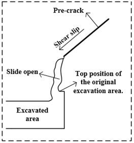
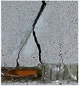
The failure of specimen C5 is shown in Fig. 9. It can be seen from the figure that shear crack or wing crack opening degree developed at the left tip of pre-existing fissure has obviously increased, and the fracture surface has been shifted up and down. The overall relative displacement of pre-existing fissure surface occurred when specimen was destroyed. Comparing the top position of unloaded zone with the top position of original unloaded zone in the figure, obvious vertical displacement can be observed. This is because when pre-existing fissure propagated, penetrated and coalesced, the two parts of the fracture surface were relatively slipped. Besides, the left tip of pre-existing fissure had generated micro cracks during staged unloading, and the micro cracks had penetrated through the unloading zone. The zone slides with sliding of the fracture surface, causing the collapse of the top of unloading zone. During the test, shear-slip failure mode in the zone above unloading zone mostly occurred in the condition that specimen occurred failure when it is unloaded to the left tip of pre-existing fissure. The emergence of this kind of failure mode requires that the left tip of pre-existing fissure first generate a branch crack that intersects staged unloading zone. During subsequent staged unloading, there is a large shear stress on pre-existing fissure surface, prompting a large slip dislocation of the rock part along the pre-existing fissure surface. This caused the rock in the upper part of unloading zone to slide downward and destroy. When the shear-slip failure mode of the zone above staged unloading zone occurs, the overall failure modes of specimen are shear failure and mixed failure.
Fig. 9Schematic diagram of C5 failure mode
a)
b)
(3) Mixed shear-separation failure.
The destruction of specimen D5 is shown in Fig. 10. The shearing slip on pre-existing fissure surface caused a significant vertical displacement at the top of unloading zone. At the same time, the initial micro crack of left tip together with a new branch crack that generated in pre-existing fissure, cutting a separate part of the top of unloading zone. This is a mixed destruction of two failure modes.
Fig. 10Schematic diagram of D5 failure mode
a)
b)
(4) Compression-shear failure.
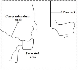
The destruction of specimen E5 is shown in Fig. 11. Below pre-existing fissure, micro-cracks are numerous and dense in the unexcavated zone in front of unloading zone, and the entire zone exists a high degree of crushing, showing obvious compression-shear failure characteristics. During the test, this kind of failure mode mostly occurred when pre-existing fissure angle was relatively big, and the specimen underwent overall shear failure when the excavation was unloaded to the middle of excavation zone. The emergence of this kind of failure mode requires that the normal stress on pre-existing fissure surface to be relatively big. Moreover, the failure of unexcavated zone under pre-existing fissure is caused by shearing action. When the compression shear failure of the zone above staged unloading zone occurs, the failure of whole specimen is mostly a shear failure mode.
Fig. 11Schematic diagram of E5 failure mode
a)
b)
6. Conclusions
A new staged unloading test method under constant normal load was used to investigate crack initiation, propagation, and coalescence failure mechanisms of pre-existing fissure specimens under staged unloading. The following conclusions are drawn.
1) During the staged unloading process, the pre-existing fissure tip gradually initiated branch cracks and propagated steadily; when unloading to a certain degree, the unstable propagation of branch crack leads to the overall failure of specimen.
2) In the staged unloading process, tension cracks were generated only in the middle of fissure when the fissure angle was small; the initial cracks near unloading zone showed tensile cracks and shear cracks, while the cracks far away unloading zone were all tensile wing cracks.
3) Under the staged unloading conditions, the secondary coplanar crack showed a faster shear-through speed, but the coalescence of wing cracks, shear coalescence and mixed tensile-shear coalescence of the secondary inclined cracks showed a slower speed.
4) Under the staged unloading conditions, depending on the dip angle of the joint, four modes of failure occurred: separation failure, shear-slip failure, mixed shear-separation failure and compression-shear failure. In modern engineering processes under staged excavation conditions, different damages may also occur due to different fault dip angles, therefore appropriate protection measures can be carried out accordingly. Therefore, different failure modes of the specimens in this research have a certain guiding role for the modern engineering.
References
-
Brace W. F., Bombolakis E. G. A note on brittle crack growth in compression. Journal of Geophysical Research, Vol. 68, Issue 12, 1963, p. 3709-3713.
-
Wong R. H. C., Chau K. T. Crack coalescence in a rock-like material containing two cracks. International Journal of Rock Mechanics and Mining Sciences, Vol. 35, Issue 2, 1998, p. 147-164.
-
Pu C. Z., Cao P., Zhao Y. L., et al. Numerical analysis and strength experiment of rock-like materials with multi-cracks under uniaxial compression. Rock and Soil Mechanics, Vol. 31, Issue 11, 2010, p. 3661-3666.
-
Wang Y., Guo P., Ren W., et al. Laboratory investigation on strength characteristics of expansive soil treated with jute fiber reinforcement. International Journal of Geomechanics, Vol. 17, Issue 11, 2017, p. 04017101, https://doi.org/10.1061/(ASCE)GM.1943-5622.0000998.
-
Lin Q. B., Cao P., Li K. H., et al. Experimental study on acoustic emission characteristics of jointed rock mass by double disc cutter. Journal of Central South University, Vol. 25, Issue 2, 2018, p. 357-367.
-
Wang Y. X., Guo P. P., Dai F., Li X., et al. Behaviour and modelling of fiber reinforced clay under triaxial compression by using the combining superposition method with the energy based homogenization technique. International Journal of Geomechanics, 2018, https://doi.org/10.1061/(ASCE)GM.1943-5622.0001313.
-
Lin Q. B., Cao P., Wang H., Cao R. H. An experimental study on cracking behavior of pre-cracked sandstone specimens under seepage pressure. Advances in Civil Engineering, Vol. 2018, 2018, p. 4068918.
-
Lin Q. B., Cao P., Cao R. H. Experimental investigation of jointed rock breaking under a disc cutter with different confining stresses. Comptes Rendus Mecanique, Vol. 346, Issue 9, 2018, p. 833-843.
-
Yang S. Q., Jing H. W. Evaluation on strength and deformation behavior of red sandstone under simple and complex loading paths. Engineering Geology, Vol. 164, 2013, p. 1-17.
-
Huang Y. H., Yang S. Q. Particle flow simulation of macro-and meso-mechanical behavior of red sandstone containing two pre-existing non-coplanar cracks. Chinese Journal of Rock Mechanics and Engineering, Vol. 33, Issue 8, 2014, p. 1644-1653.
-
Jiang M. J., Chen H., Zhang N., et al. Distinct element numerical analysis of crack evolution in rocks containing pre-existing double flaw. Rock and Soil Mechanics, Vol. 35, Issue 11, 2014, p. 3259-3268.
-
Jiang M. J., Zhang N., Shen Z. F., et al. DEM analyses of crack propagation in flawed rock mass under uniaxial compression. Rock and Soil Mechanics, Vol. 36, Issue 11, 2015, p. 3293-3300.
-
Li J. L., Meng Q. Y. Anisotropic study of unloaded rock mass. Chinese Journal of Rock Mechanics and Engineering, Vol. 20, Issue 3, 2001, p. 338-341.
-
Li J. L., Wang L. H. Study of size effect of unloaded rock mass. Chinese Journal of Rock Mechanics and Engineering, Vol. 22, Issue 12, 2003, p. 2032-2036.
-
Huang D., Huang R. Q. Physical model test on deformation failure and crack propagation evolvement of cracked rocks under unloading. Chinese Journal of Rock Mechanics and Engineering, Vol. 29, Issue 3, 2010, p. 502-512.
-
Song Y. Q., Li M., Wang X., et al. Observation of marble with single pre-existing fissure using high-speed photography under loading and unloading conditions. Journal of China University of Mining and Technology, Vol. 43, Issue 5, 2014, p. 773-781.
-
Song Y. Q., Li M., Wang X., et al. Observation of marble with two pre-existing fissure using high-speed photography under loading and unloading conditions. Journal of China University of Mining and Technology, Vol. 1, 2015, p. 2679-2689.
-
Lin H., Xiong W., Yan Q. X. Three-dimensional effect of tensile strength in the standard Brazilian test considering contact length. Geotechnical Testing Journal, Vol. 39, Issue 1, 2016, p. 137-143.
-
Wang H., Lin H., Cao P. Correlation of UCS rating with Schmidt hammer surface hardness for rock mass classification. Rock Mechanics and Rock Engineering, Vol. 50, Issue 1, 2018, p. 195-203.
-
Wu G., Zhang L. Studying unloading failure characteristics of a rock mass using the disturbed state concept. International Journal of Rock Mechanics and Mining Sciences, Vol. 41, Issue 3, 2004, p. 1-7.
-
Zhao Y., Wang Y., Wang W., et al. Modeling of non-linear rheological behavior of hard rock using triaxial rheological experiment. International Journal of Rock Mechanics and Mining Sciences, Vol. 93, 2017, p. 66-75.
-
Zhang W. J., Lu W. B., Yang J. H., et al. Cracking characteristics and influential factors of surrounding rocks induced by excavation unloading in deep tunnel. Rock and Soil Mechanics, Vol. 34, Issue 9, 2013, p. 2690-2698.
-
Zhao Y. L., Luo S. L., Wang Y. X., et al. Numerical analysis of karst water inrush and a criterion for establishing the width of water-resistant rock pillars. Mine Water and the Environment, Vol. 36, Issue 4, 2017, p. 508-519.
-
Li X. B., Cao W. Z., Zhou Z. L., et al. Influence of stress path on excavation unloading response. Tunneling and Underground Space Technology, Vol. 42, Issue 42, 2014, p. 237-246.
-
Yin T. B., Li X. B., Yin Z. Q., et al. Research and comparison of static and dynamic mechanical properties of sandstone after high temperature. Chinese Journal of Rock Mechanics and Engineering, Vol. 31, Issue 2, 2012, p. 273-279.
About this article

This work was supported by the National Natural Science Foundation of China (No. 11772358) and the Fundamental Research Funds for the Central South Universities, China (No. 2018zzts730).
