Abstract
In this paper, the dynamic responses of a moving vehicle traversing over railway track with fastening system failure were investigated using a vehicle/track coupling system model. In this model, the moving vehicle is developed by multi-body dynamics, and the direct fixation track is modeled by finite element method, where the rail is treated as an Euler-Bernoulli beam supported by fastening systems. An invalidation factor is used to determine the failure of the fastening system. The Hertzian spring is adapted to model the wheel/rail contact force between the moving wheel set and the rail. The proposed vehicle/track system model is verified with some field testing results in Zhengzhou subway. To solve the vehicle/track system model with nonlinear contact force, an iterative procedure is proposed. The effects of fastening system failure on the responses of the vehicle and track are investigated. It indicates that the wheel/rail contact force varies abruptly when the vehicle passing over the fastening system failure zone, which result in track deterioration.
1. Introduction
To reduce the costs of construction and dead weight, the direct fixation track is generally located on aerial sections or in tunnels in metro systems. It is indicated that direct fixation track construction has been credited with saving millions of dollars by eliminating the need for crossties and ballast [1]. During the construction of a direct fixation track using the top-down method, various installation faults can result in fastening system failure [2]. When a vehicle moves over railway track with failed fastening system, the excessive interaction between the vehicle and track may occur, which may lead to accelerated degradation of the railway track and vehicle components.
Nowadays the finite element method is widely used in civil engineering infrastructure analysis, such as bridges, railway track and railway embankment [3-7]. Yang S. C. brought out an enhanced finite element method for the analysis of vertical train/track interactions by adding a node at the point of loading and this model was validated by comparing the results with field testing data and other numerical models reported in the literature [8]. Esmaeili et al. developed a finite element method model, where the rail and sleeper were modeled as beam elements and a series of lumped masses with linear springs and dashpots were used to model the ballast, subballast and subgrade, to investigate the dynamic behavior of ballasted railway track subjected to earthquake motion and the efficient excited length of the track during the Kobe earthquake was determined [9, 10]. Mehrali et al. built a vertically coupled vehicle/slab track model using the finite element method, where the vertical stiffness of the track bed is assumed to be a random variable using Monte Carlo simulation and pointed out that the uncertainty in track bed stiffness has a major effect on rail and slab deflections [11]. Lei et al. presented a new type track element model with three layer beams, including rail, concrete slab and hydraulically bonded layer. Based on the track element, a vehicle/track/subgrade coupling system was been developed and the dynamic behavior of track transition from conventional ballast track to slab track was studied [12]. Yan et al. analyzed the effect of the ladder track parameters on the track vibration in time domain using the vehicle/track coupling model and performed an optimization of the mechanical properties of the ladder track to reduce the track vibrations using the multipoint approximation method [13]. Ling et al. presented a dynamic train/track model, where the metro train and a slab track was developed using multi-body dynamics and the finite element method, and did some experimental and numerical investigation of the effect of rail corrugation on the dynamic behavior of rail fastenings [14]. From the above researches, different vehicle/track system models with finite element method were presented and some useful results were put forwarded. However, relatively little information is available on the dynamic responses of the direct fixation track, especially for the direct fixation track with fastening system failure.
A rail fastening system is an important component of railway track, which can ensure the stability and quality of tracks and the operational safety of railway vehicles. In this paper, the influences of fastening system failure on track dynamics are investigated. Firstly, a vehicle/track dynamic model is presented, in which the vehicle is developed using multi-body dynamics and the track is modeled with finite element method. Secondly, due to the nonlinear wheel/rail contact force, an iterative method is performed to solve the vehicle/track coupling model. Thirdly, the vehicle/track system model is validated with some field testing results in Zhengzhou subway. Fourthly, the influences of fastening system failure on the track and vehicle responses are investigated. Results of the wheel/rail contact force, carbody acceleration and rail displacement are presented thereafter.
2. Modeling of vehicle/track system
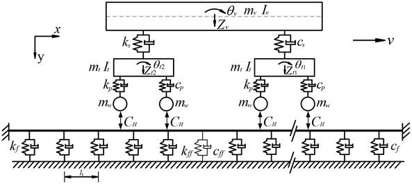
In this study, a direct fixation track is considered, where the rail is directly fastened to the track support [2]. The dynamic model of a metro vehicle traveling over a direct fixation track with fastening system failure is shown in Fig. 1, and in this model the wheel and the rail are linked by the assumed wheel/rail interaction relationship [11, 15, 16]. To simplify the formulation of the equations of motion for rail vibration due to moving vehicle in an analytical way, only the vertical vibration of the dynamic model is considered in this study with the following assumptions adopted:
(1) The vehicle runs over the rail at constant speed [17].
(2) The vehicle is composed of one car body, two identical bogies and four identical wheel sets, which are regarded as rigid bodies, as shown in Fig. 1.
(3) For the direct-fixation track, the rail is supported by a series of fastening system with the same spacing. Each fastening system is modeled as a linear spring-dashpot unit including the fastening system with failure.
(4) To simplify the equation of this system, the roughness of the rail surface is neglected in this study.
(5) The wheel/rail contact force is represented by a nonlinear Hertzian spring.
Fig. 1A metro vehicle running over a direct-fixation track with fastening system failure
2.1. Vehicle model
As shown in Fig. 1, the car body is supported at each side by a double-axle bogie through secondary suspension systems and each bogie is linked through the primary suspension systems. Both of the primary and secondary suspension systems are modeled as a linear spring-dashpot units. For car body and each bogie, there are two degree of freedoms, designated by vertical displacement and rotation about the center point (see Fig. 1). Each wheel set is subjected to a contact force induced by the wheel/rail contact and only the vertical displacement is considered herein. The definition of the symbols and parameters of a metro vehicle in Zhengzhou subway is list in Table 1.
Table 1Notations and parameters of a Zhengzhou metro vehicle
Parameters | Notation | Value |
Mass of car body | 21800 kg | |
Mass of bogie | 1300 kg | |
Mass of wheel set | 900 kg | |
Mass moment of inertia of car body | 2.5×10⁵ kg m2 | |
Mass moment of inertia of bogie | 800 kg m2 | |
Stiffness of primary suspension | 1.4×10⁶ N/m | |
Stiffness of secondary suspension | 4.8×10⁵ N/m | |
Damping of primary suspension | 3.0×10⁴ N s/m | |
Damping of secondary suspension | 1.6×10⁵ N s/m | |
Half of distance between two bogie centers | 6.3 m | |
Half of distance between two axles in each bogie | 1.1 m |
Using D’Alembert principle, the vertical and rotation equation motion of the car body can be written as:
where and are the vertical displacement and pitch rotation of the car body, and are the vertical displacement of the front and rear bogie, respectively.
Similarly, the vertical and rotation equation motion of the front and rear bogie can be written as:
where and are the pitch rotation of the front and rear bogie, respectively. The equations of motion for the four wheel sets can be written as:
where is the vertical displacement of the ith wheel set ( = 1–4); is the contact force between the rail and the th wheel set, which is described by the nonlinear Hertzian theory [18, 19]:
where is the vertical displacement of the rail at the point where the th wheel set is located; is the Hertizan constant and = 9.37×10¹⁰ N/m3/2.
By combining Eqs. (1) to (11) together, the equations of motion for the vehicle system can be given as:
where , and denote the mass, damping and stiffness matrices, respectively; , and denote the accelerations, velocities and displacements, respectively; is the external force vector acting on the vehicle system.
2.2. Track model
In the present paper, only the vertical vibrations of the direct-fixation track are studied. As shown in Fig. 1, the track model is composed of rail and fastening system, where the rail is treated as an Euler beam and discretely supported by a series of fastening system with the same spacing. Each fastening system is modeled as a spring-dashpot unit. The definition of the symbols and parameters of the direct-fixation track in Zhengzhou subway is list in Table 2.
Table 2Notations and parameters of a direct-fixation track
Parameters | Notation | Value |
Rail mass per unit length | 60.64 kg/m | |
Elastic modulus of rail | 2.06×10¹¹ N/m2 | |
Moment of inertia of rail | 3.217×10⁻⁵ m4 | |
Spacing of fastening system | 0.625 m | |
Stiffness of fastening system | 1.6256×10⁷ N/m | |
Damping of fastening system | 1.0×10⁴ N/m |
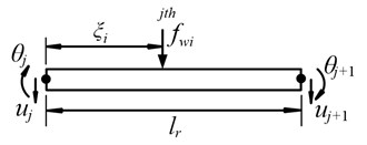
In reality, railway track is an infinite structure, which can be modeled as a periodic structure consisting of identical structural components [20, 21]. To investigate the track vibration due to moving vehicle, a considerable length of track is usually adopted instead of the infinite track, where the ends of the rail are assumed to be simple supported [18, 22] or fixed [23, 24]. In this study, each end of the rail is assumed to be fixed, as shown in Fig. 1. To reduce the effects of unrealistic boundary constraints of the track subjected to moving vehicle, the vehicle should be placed as far as possible from the rail ends. In Lei’s study, 20 m is long enough to eliminate the effect of the boundary [25], which is also used in the paper. Lou et al. investigated the effect of the rail element length on the track dynamic responses under moving loads and pointed that taking two times sleeper space as rail element length was sufficient to capture the track vibration characteristics [24]. In this paper, the rail element length is set as one sleeper space and the rail element is supported by two adjacent fastening systems. As shown in Fig. 2, rail element has four degree of freedom (DOFs), i.e. two vertical displacements and and two rotations and at two nodes. The vertical displacement of the th typical rail element at point and time can be expressed in terms of the shape function matrix and nodal displacement of the rail element:
where denote the nodal displacement vector of the rail element, , denote the shape function matrix of the rail element, which is defined by cubic Hermitian interpolation functions:
where is the length of the rail element, which is equal to sleeper spacing in this paper.
Fig. 2DOF of rail element and applied loads
Thus, the mass and stiffness matrix of the rail element can be expressed as:
where is the mass per unit length, is the elastic modulus of rail and is the moment of inertia of rail.
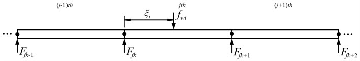
As shown in Fig. 3, the rail is subjected to the wheel/rail contact forces and the supported forces from the fastening system. Therefore, the equation of motion of the rail, including all the rail nodes can be expressed as:
where is the force from the th fastening system acting on the rail:
Fig. 3Illustration of a track model
To study the effect of fastening system failure on the track vibration, the stiffness and damping for the fastening system with failure (see Fig. 1) are set as:
where is the invalidation factor to characterize the failure of fastening systems.
Subsequently, one can substitute Eqs. (17), (18) and (19) into Eq. (16), and move the terms with to the left side of the differential equation. The equation of motion of the track system with fastening system failure under moving vehicle can be expressed as:
where , and denote the mass, damping and stiffness matrices of the track system, respectively, , and denote the accelerations, velocities and displacements of the rail nodes and sleepers, respectively, is the external force vector acting on the track system.
3. Iterative solutions
Fig. 4Flowchart of the iterative solution
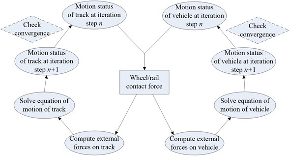
As indicated in Eq. (11), the wheel/rail contact force between wheel and rail is modeled using a nonlinear Hertzian spring, which is nonlinear in nature for the interaction of vehicle/track system. To solve the Eqs. (12) and (20) simultaneously, an iterative scheme for the time step is put forwarded as follows [26]:
(a) Use the motion statuses of the vehicle and track at the last iteration step to compute the wheel/rail contact forces in Eq. (11) for the current iteration step .
(b) Compute the external forces on the vehicle and track, respectively.
(c) Solve the equation of motion of the vehicle and the track in Eqs. (12) and (20) using a step-by-step integration method such as the Newmark- method [27], to determine the vehicle and track responses at iteration step .
(d) Compare the motions statuses of track and vehicle at iteration step with iteration step , and if the following convergence criterion is reached for both vehicle and track, a next time step can be started. Otherwise, go to a next iteration step from (a).
The allowable tolerance for the convergence criterion is set as 10−6 m in this paper, which are found to be sufficient to determine the solution with acceptable accuracy from numerical comparison.
4. Model validation
In order to validate the vehicle/track system model in this paper, the authors compare some numerical results computed by this model with some field testing results in Zhengzhou subway. This case is used to verify the algorithm for the calculation of the dynamic response of the track subjected to moving vehicle. In the field testing, the vehicle is moving over a direct-fixation track without fastening system failure at a speed of = 62 km/h. Taking the displacement of the rail for example, the numerical result and the field testing result are compared, as shown in Fig. 5.
Fig. 5Model validation
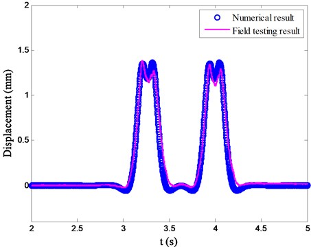
As can be seen from Fig. 5, the response obtained by the present vehicle/track system model agrees well with the field testing data. On the other hand, it shows that there are four peaks induced by the four wheel sets.
5. Numerical investigations
In this numerical simulation, the invalidation factor is set as 50 % (Case one) and 100 % (Case two) to study the effect of fastening system failure on the vehicle/track system vibration. The normal track without fastening system failure, that is the invalidation factor = 0 (Case three), is also computed to compare the dynamic effect of fastening system failure. In the above three cases, only one fastening system failure is considered, which is the most common status in reality. The properties of the vehicle and track used in this study are listed in Table 1 and Table 2, respectively. In Zhengzhou subway, the maximum operation speed of the train is 80 km/h, which is also used in the following calculation.
5.1. Wheel/rail contact force
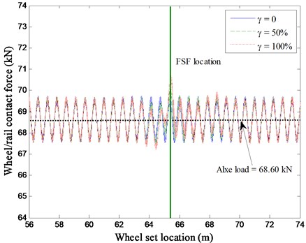
The wheel/rail contact force is a parameter used to assess the likelihood of excessive wheel or rail deterioration. The wheel/rail contact force of the first wheel set against its location for the above three cases with the invalidation factor = 0, 50 % and 100 % are computed, as shown in Fig. 6.
When the vehicle travels over the normal track, that is the invalidation factor = 0 in Fig. 6, the wheel/rail contact force varies from 67.52 kN to 69.76 kN, which fluctuates above the vehicle axle load (68.60 kN), this can be attributed to the periodical support from railway track. In Case one and Case two, the fastening system failure (FSF) location from the vehicle initial location in x coordinate in Fig. 1 is set as 65.2 m. When the wheel set enters into the fastening system failure zone, the wheel/rail contact force increases suddenly. The maximum wheel/rail contact forces are 70.15 and 70.71 kN, for the two corresponding cases with the invalidation factor = 50 % and 100 %, respectively. It also depicts that, with higher deterioration degree of the fastening system failure, a little larger wheel/rail contact force occurs. The maximum wheel/rail contact force that in the fastening system failure area may result in excessive wear and speed up the track deterioration.
Fig. 6Wheel/rail contact force
5.2. Acceleration of carbody
Fig. 7Acceleration of carbody
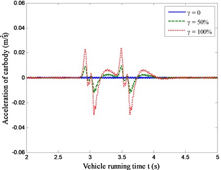
For the sake of better riding comfort of passing vehicle, the carbody acceleration responses of moving vehicle should be kept within an allowable limit. To investigate the presence of fastening system failure on the vehicle riding comfort, numerical simulations were performed using the vehicle/track system model. As shown in Fig. 7, the acceleration responses of carbody running over the railway track with fastening system failure (Case one and Case two) against vehicle running time are compared with that of the normal track (Case three).
An observation from Fig. 7 indicates that, compared with Case three (invalidation factor = 0), there are two oscillations in the time history of the carbody acceleration responses for Case one and Case two (invalidation factor = 50 % and 100 %). That is because the front and rear bogie enters the fastening system failure zone one by one. On the other hand, there is a rapidly increase in the magnitude of the acceleration responses for the vehicle as much higher deterioration degree of the fastening system failure. The maximum acceleration responses of vehicle for Case one and Case two are about 14.69 times and 36.56 times higher than that for Case three. It can be seen that the fastening system failure can deteriorate the vehicle riding comfort suddently.
5.3. Displacement of rail
Due to the failure of the fastening system, the railway track supporting stiffness will be weaken, which may result in much heavier track vibration. In this section, the displacements of the rail at the fastening system failure location against vehicle running time for Case one, Case two and Case three are computed, as shown in Fig. 8.
Fig. 8Displacements of rail
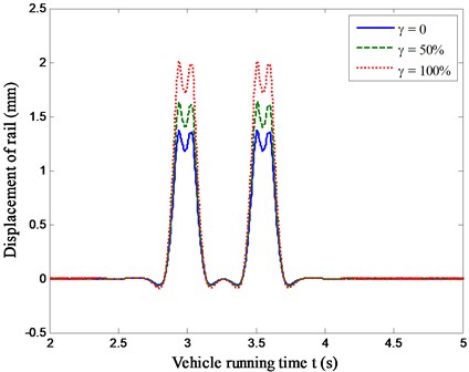
Fig. 8 indicates that the maximum value of the rail displacement with the invalidation factor = 0, 50 % and 100 % are 1.37 mm, 1.63 mm and 2.01 mm, respectively. It can be seen that the displacements of rail for the tracks with fastening system failure are much higher than that of the normal track due to low stiffness and the fastening system failure amplifies the rail vibration. Therefore, the track with fastening system failure zone undergoes much more damage than the normal track, where the maintenance cost will be higher. Evidently, the abrupt change of rail displacement may reduce riding comfort of the vehicle, as discussed in Section 5.2.
6. Concluding remarks
In order to investigate the effect of the fastening system failure on the dynamic responses of the track, a dynamic model of vehicle/track system was developed. In this model, the vehicle was built using multi-body dynamics and the railway track was modeled with finite element method. Due to the nonlinear wheel/rail contact force, an iterative solution was performed to solve the vehicle/track system model. The proposed vehicle/track system model is verified with some field testing results in Zhengzhou subway.
When the wheel set enters into the fastening system failure zone, the wheel/rail contact force increases suddenly, which may amplify the magnitude of the carbody acceleration and rail displacement at the fastening system failure location. With higher deterioration degree of the fastening system failure, the dynamic responses of vehicle/track system, including wheel/rail contact force, carbody acceleration and rail displacement, will be much larger. It means that the fastening system failure may speed up the track deterioration and reduce riding comfort of the vehicle, which should be considered during daily maintenance.
This paper presents an iterative solution for a vehicle/track system model and studies some preliminary influences of fastening system failure on the dynamic responses of running vehicle and track components. To detect the fastening system failure of a ballasted track, some evolutionary algorithms involved into the vehicle/track system model such as genetic algorithm, neural network algorithm, will be carried out in a forthcoming paper.
References
-
Track Design Handbook for Light Rail Transit. Transportation Research Board, National Research Council, 2000.
-
Yang S. C, Kim E. Effect on vehicle and track interaction of installation faults in the concrete bearing surface of a direct-fixation track. Journal of Sound and Vibration, Vol. 331, Issue 1, 2012, p. 192-212.
-
Humar J. L. Dynamics of Structures. Third Edition, CRC Press, London, England, 2012.
-
Jesus A. H., Dirnitrovova Z., Silva M. A. G. A statistical analysis of the dynamic response of a railway viaduct. Engineering Structures, Vol. 71, 2014, p. 244-259.
-
Shi J., Burrow M., Chan A. H., Wang Y. J. Measurements and simulation of the dynamic responses of a bridge-embankment transition zone below a heavy haul railway line. Proceedings of the Institution of Mechanical Engineers Part F-Journal of Rail and Rapid Transit, Vol. 227, Issue F3, 2013, p. 254-268.
-
Wei B., Xia Y., Liu W. Lateral vibration analysis of continuous bridges utilizing equal displacement rule. Latin American Journal of Solids and Structures, Vol. 11, Issue 1, 2014, p. 75-91.
-
Xia Y., Nassif H., Hwang E., Linzell D. Optimization of design details in orthotropic steel decks subjected to static and fatigue loads. Transportation Research Record, Issue 2331, 2013, p. 14-23.
-
Yang SC. Enhancement of the finite-element method for the analysis of vertical train-track interactions. Proceedings of the Institution of Mechanical Engineers Part F-Journal of Rail and Rapid Transit, Vol. 223, Issue 6, 2009, p. 609-620.
-
Esmaeili M., Noghabi H. H. Investigating seismic behavior of ballasted railway track in earthquake excitation using finite-element model in three-dimensional space. Journal of Transportation Engineering, Vol. 139, Issue 7, 2013, p. 697-708.
-
Wang Y. J. Discussion of “Investigating seismic behavior of ballasted railway track in earthquake excitation using finite-element model in three-dimensional space” by Morteza Esmaeili and Hamidreza Heydari Noghabi. Journal of Transportation Engineering, Vol. 140, Issue 9, 2014, p. 7014001.
-
Mehrali M., Mohammadzadeh S., Esmaeili M., Nouri M. Investigating vehicle-slab track interaction considering random track bed stiffness. Scientia Iranica, Vol. 21, Issue 1, 2014, p. 82-90.
-
Lei X., Zhang B. Analysis of dynamic behavior for slab track of high-speed railway based on vehicle and track elements. Journal of Transportation Engineering, Vol. 137, Issue 4, 2011, p. 227-240.
-
Yan Z., Markine V., Gu A., Liang Q. Optimisation of the dynamic properties of the ladder track to control rail vibration using the multipoint approximation method. Journal of Vibration and Control, Vol. 20, Issue 13, 2014, p. 1967-1984.
-
Ling L., Li W., Shang H., Xiao X., Wen Z., Jin X. Experimental and numerical investigation of the effect of rail corrugation on the behaviour of rail fastenings. Vehicle System Dynamics, Vol. 52, Issue 9, 2014, p. 1211-1231.
-
Zhang J., Gao Q., Tan S. J., Zhong W. X. A precise integration method for solving coupled vehicle-track dynamics with nonlinear wheel-rail cntact. Journal of Sound and Vibration, Vol. 331, Issue 21, 2012, p. 4763-4773.
-
Lei X., Wang J. Dynamic analysis of the train and slab track coupling system with finite elements in a moving frame of reference. Journal of Vibration and Control, Vol. 20, Issue 9, 2014, p. 1301-1317.
-
Wang Y. J., Wei Q. C., Shi J., Long X. Y. Resonance characteristics of two-span continuous beam under moving high speed trains. Latin American Journal of Solids and Structures, Vol. 7, Issue 2, 2010, p. 185-199.
-
Li Z. G., Wu T. X. On vehicle/track impact at connection between a floating slab and ballasted track and floating slab track’s effectiveness of force isolation. Vehicle System Dynamics, Vol. 47, Issue 5, 2009, p. 513-531.
-
Shi J., Chan A. H., Burrow M. P. N. Influence of unsupported sleepers on the dynamic response of a heavy haul railway embankment. Proceedings of the Institution of Mechanical Engineers Part F – Journal of Rail and Rapid Transit, Vol. 227, Issue 6S, 2013, p. 657-667.
-
Delossantos M. A., Martinez J., Cardona S. A convolution application to determine the dynamic-response of a railway track. Mechanical Systems and Signal Processing, Vol. 9, Issue 6, 1995, p. 707-708.
-
Zhang Y. W., Lin J. H., Zhao Y., Howson W. P., Williams F. W. Symplectic random vibration analysis of a vehicle moving on an infinitely long periodic track. Journal of Sound and Vibration, Vol. 329, Issue 21, 2010, p. 4440-4454.
-
Dimitrovova Z., Rodrigues A. Critical velocity of a uniformly moving load. Advances in Engineering Software, Vol. 50, 2012, p. 44-56.
-
Zhu J. J., Ahmed A., Rakheja S., Khajepour A. Development of a vehicle-track model assembly and numerical method for simulation of wheel-rail dynamic interaction due to unsupported sleepers. Vehicle System Dynamics, Vol. 48, Issue 12, 2010, p. 1535-1552.
-
Lou P., Zhong X. G.,. Tang J. F., Zeng Q. Y. Finite-element analysis of discretely supported rail subjected to multiple moving concentrated forces. Proceedings of the Institution of Mechanical Engineers Part F – Journal of Rail and Rapid Transit, Vol. 220, Issue 3, 2006, p. 305-315.
-
Lei X., Noda N. A. Analyses of dynamic response of vehicle and track coupling system with random irregularity of track vertical profile. Journal of Sound and Vibration, Vol. 258, Issue 1, 2002, p. 147-165.
-
Long X., Wei Q., Zheng F. Dynamic analysis of railway transition curves. Proceedings of the Institution of Mechanical Engineers Part F – Journal of Rail and Rapid Transit, Vol. 224, Issue F1, 2010, p. 1-14.
-
Wang Y. J., Wei Q. C., Yau J. D. Interaction response of train loads moving over a two-span continuous beam. International Journal of Structural Stability and Dynamics, Vol. 13, Issue 1, 2013, p. 1350002.
About this article

The research reported herein is partly supported by the Fundamental Research Funds for the Central Universities (Grants No. 2014JMB096). This support is gratefully acknowledged.
