Abstract
In order to examine both static and dynamic behaviors of Concrete Filled Carbon Fiber Reinforced Polymer Sheet Tube (CFCST) columns, experimental tests have been performed. The main variables of this experimental program included the number and wrapping angles of CFRP sheets. Stress versus strain relation of CFCST specimens was investigated by uni-axial tests. And, six full-scaled CFCST columns subjected to quasi-static lateral loading, as well as constant axial compression, were tested. Finally, an analytical procedure to predict the response of CFCST columns subjected to both axial and lateral loadings has been suggested in conjunction with the findings from the experimental tests.
1. Introduction
Column should be designed to maintain reasonable response to lateral load as well as vertical load. Conventional reinforced concrete columns have generally large cross-section with high longitudinal reinforcement ratio to resist the increased lateral load demand. Under the same level of lateral load, concrete filled CFRP tube columns had sufficient lateral resistance in spite of using a reduced cross-section compared to conventional reinforced concrete columns [1-4]. Lateral confinement usually triggers an improvement of concrete compressive strength, as well as the flexural capacity of RC columns [5-8]. Carbon fiber reinforced polymer (CFRP) sheet tube is one of the most efficient methods to enhance the lateral confinement of RC columns.
In order to examine both static and dynamic behaviors of Concrete Filled Carbon Fiber Reinforced Polymer Sheet Tube (CFCST) columns, in the first stage, fourteen circular Concrete Filled CFRP Sheet Tube (CFCST) specimens (300 mm×600 mm) subjected to uni-axial compression were tested to investigate the stress vs. strain relationship. Different from carbon fiber tubes, CFRP sheet tubes can be manufactured at any target angle exactly. First, the CFRP sheet was attached perpendicular to the longitudinal direction of specimens because the function of the first CFRP sheet is the same as the function of transverse reinforcement. The number and/or wrapping angle of CFRP sheet are different in each specimen. In the second stage, six full-scaled CFCST columns subjected to both vertical and lateral loadings were tested to examine their performance. Finally, analytical approach for estimation of stress-strain relation of CFCST column subjected to lateral loading has been proposed in conjunction with the findings obtained from experimental tests.
2. Experiments
2.1. Uni-axial loading test
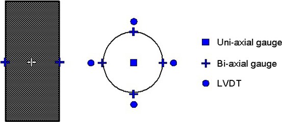
A circular mandrel of 300 mm in diameter was made with steel plate; then, a thin polyethylene film sheet was wrapped between CFRP tube and the steel mandrel. Finally, CFRP sheets were attached to the CFRP tube according to their target direction using epoxy resin. An epoxy resin used in this construction is applicable in between 15 and 25 degrees in temperature and needs 7 days of curing time. First CFRP sheet was attached 90 degrees in respect to the longitudinal direction of the column, then 3, 5, or 7 plies of CFRP sheets were attached at different angles in respect to the longitudinal direction of specimens; those are 90±0, 90±30, 90±45, 90±60, 90±75, and 90±90. In this test, the main test variables were the wrapping angle and the number of CFRP sheets, so as to investigate the performance of concrete filled CFRP sheet tube corresponding to the manufacturing method by CFRP sheets. After Concrete filled CFRP sheet tubes were cured at least three days in the air, they were cut by 600 mm in length for uni-axial loading test. Details of the specimens are summarized in Table 1. Figure 1 shows the measuring points of uni-axial test specimens. One concrete gauge was embedded into the center of the specimen to measure the inner concrete strain; four bi-axial gauges measured the axial strain of the CFRP sheet tube; and four LVDTs measured axial deformation.
Table 1Experimental test specimens for uni-axial tests
Specimens | No. of specimens | Thickness of tube (mm) | 90° | 0° | 30° | 45° | 60° | 75° |
0-3T | 1 | 1.2 | 1 | 2 | ||||
0-5T | 1 | 2.0 | 1 | 4 | ||||
30-3T | 1 | 1.2 | 1 | 2 | ||||
30-7T | 1 | 2.8 | 1 | 6 | ||||
45-3T | 1 | 1.2 | 1 | 2 | ||||
45-5T | 1 | 2.0 | 1 | 4 | ||||
45-7T | 1 | 2.8 | 1 | 6 | ||||
60-3T | 1 | 1.2 | 1 | 2 | ||||
60-5T | 1 | 2.0 | 1 | 4 | ||||
75-3T | 1 | 1.2 | 1 | 2 | ||||
75-5T | 1 | 2.0 | 1 | 4 | ||||
75-7T | 1 | 2.8 | 1 | 6 | ||||
90-3T | 1 | 1.2 | 3 | |||||
90-5T | 1 | 2.0 | 5 | |||||
Control | 3 | - | - | - | - | - | - | - |
Total | 17 |
Fig. 1Measuring points in the uni-axial test
2.2. Quasi-static cyclic lateral loading test
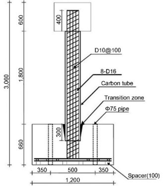
Six concrete filled CFRP sheet tube (CFCST) columns were constructed. All specimens (full-scale) were 3,060 mm in length and 300 mm in diameter. In this series, CFRP sheet was manufactured with 90±0 and 90±45 in respect to the longitudinal direction of the CFRP tube. Figure 2 shows typical configuration of CFCST column specimens.
The base-block was rigidly anchored to the strong floor in the laboratory and its dimension is 1.2 m×1.2 m in the plan and 0.66 m in the height. All longitudinal reinforcement of CFCST column was sufficiently anchored within the base-block and they had 90-degree hooks. For the base-block, longitudinal and transverse reinforcement were determined to sufficiently resist bending moment and shear force induced at the expected peak loads. The CFRP sheet tube was extended into the foundation (300 mm toward downward from the bottom of the column) to prevent unexpected early cracks occurring at around the bottom of the columns. In addition, the transition zone with rubber was installed to prevent unexpected early crack arising between CFRP tube and RC column. The top-block was connected to lateral loading system (actuator) and its dimension is 0.6 m×0.6 m in the plan and 0.6 m in the height. The amount of longitudinal and transverse reinforcement within this top-block was determined to behave top block as rigid.
Fig. 2Typical configuration of CFCST column specimens (unit: mm)
In all specimens, nominal concrete strength was 27.0 MPa and nominal yield strength of reinforcement was 400.0 MPa. Table 2 summarizes the material properties of CFRP sheet measured from the coupon test (split disk test reported that the tensile strength and modulus of elasticity of CFRP sheet were 3,790 MPa and 201 GPa, respectively).
Table 2Material properties of carbon sheet from coupon test
Tensile Strength (MPa) | Modulus of Elasticity (GPa) |
3790 | 201 |
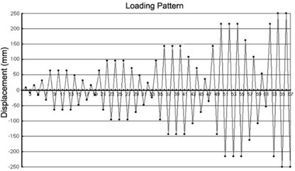
Figure 3 shows the test setup of CFCST columns. One actuator, which has 2,000 kN in capacity and ±300 mm arm length, was attached to the reaction wall and the CFCST column was subjected to quasi-static cyclic lateral loading by this actuator. The CFCST column was also subjected to constant column axial load (600 kN in compression) during the test using two actuators that were attached to rigid steel member. Figure 4 shows the cyclic lateral displacement pattern.
Fig. 3Cyclic lateral loading test set up
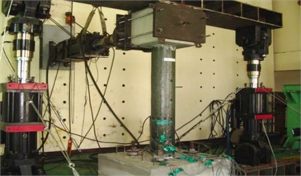
Fig. 4Lateral displacement for cyclic lateral loading tests
3. Experimental test results
3.1. Uni-axial loading test
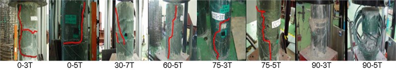
Each specimen showed different axial and lateral strain at initiation of crack and the crack direction was influenced by the wrapping direction of a CFRP sheet. An increase in axial loading triggers the expansion of inner concrete and this expansion is resisted by the lateral confinement provided by CFRP sheet tube. When the tensile strain of CFRP sheet tube exceeds the permissible maximum tensile strain of CFRP sheet, CFCST specimens cannot resist additional increase in axial compression. Thus, final failure mode was governed by tensile rupture of CFRP sheet; this failure mechanism was also observed in Lam and Teng [9].
As shown in Figure 5, the wrapping direction of CFRP sheet affects the failure line; the most efficient wrapping direction of CFRP sheet is perpendicular to the longitudinal direction of specimens. While 0-3T and 0-5T specimens resulted in 1.18 and 1.43, respectively, times nominal stress (27 MPa) for peak stress, 90-3T and 90-5T cause 2.08 and 2.70, respectively, times nominal stress for peak stress. In uni-axial testing, principal tensile strain is perpendicular to the longitudinal direction of specimen. Thus, 90-degree wrapping direction of CFRP sheet is the most efficient way to resist the principal tensile force.
Fig. 5Failure direction of uni-axial tests
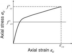
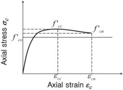
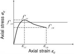
Uni-axial test results provided beneficial information in determining compressive strength of CFCST columns having variable wrapping angles. Until now, diverse research has been performed to investigate the improvement of compressive strength corresponding to the lateral confinement. However, more experimental investigation is required to characterize concrete stress vs. strain relationship for CFCST columns corresponding to wrapping direction of the CFRP sheet. As shown in Figure 6, the stress vs. strain relationship for confined concrete can be generally described as three different types. In the first type (Figure 6(a)), concrete compressive stress is continuously increased until rupture. This characteristic is generally observed when uni-axial test specimens maintain effective lateral confinement until rupture; all test specimens inhere showed this characteristic. Different from Figure 6(a), descending branch is observed in both Figures 6(b) and (c). Figure 6(b) shows that the stress at rupture exceeds unconfined peak stress (); this case is considered that some effective confinement is maintained until rupture. Figure 6(c) displays that the descending slope is quite steep after passing the peak point; this case has insufficient confinement.
Fig. 6Concrete stress vs. strain relationship
a)
b)
c)
Table 3 summarizes uni-axial test results for 14 confined and 3 unconfined concrete specimens and are the concrete stress and strain, respectively, at peak response. is the measured stress when concrete compressive strain reaches at 0.002. Uni-axial test results indicate that concrete compressive capacity is a function of the number and the wrapping angle of CFRP sheet. Concrete compressive capacity is getting improved when the wrapping angles of CFRP sheet is getting perpendicular to the direction of uni-axial compression. For example, the wrapping angles of 0-5T, 45-5T, 60-5T, and 90-5T are 0, 45, 60, and 90 degrees, respectively. The number of wrapped CFRP sheets is five for these specimens. The peak stresses of 0-5T, 45-5T, 60-5T, and 90-5T are 38.6 MPa, 41.6 MPa, 54.2 MPa, and 72.9 MPa, respectively.
Table 3Uni-axial test results
Specimen | (MPa) | (MPa) | (MPa) | |||||
0-3T | 17.5 | 31.19 | 28.57 | 0.0048 | 1.78 | 1.63 | 2.44 | 1.16 |
0-5T | 17.5 | 38.55 | 36.33 | 0.0138 | 2.20 | 2.08 | 6.90 | 1.43 |
30-3T | 17.5 | 39.37 | 32.47 | 0.0091 | 2.25 | 1.86 | 4.55 | 1.46 |
30-7T | 17.5 | 48.50 | 34.06 | 0.0201 | 2.77 | 1.95 | 10.06 | 1.80 |
45-3T | 17.5 | 43.24 | 36.21 | 0.0127 | 2.47 | 2.07 | 6.35 | 1.60 |
45-5T | 17.5 | 41.58 | 33.78 | 0.0116 | 2.38 | 1.93 | 5.81 | 1.54 |
45-7T | 17.5 | 47.56 | 37.53 | 0.0165 | 2.72 | 2.15 | 8.28 | 1.76 |
60-3T | 17.5 | 35.71 | 37.42 | 0.0158 | 2.04 | 2.14 | 7.91 | 1.32 |
60-5T | 17.5 | 54.17 | 33.56 | 0.0246 | 3.10 | 1.92 | 12.30 | 2.01 |
75-3T | 17.5 | 40.82 | 30.18 | 0.0149 | 2.33 | 1.73 | 7.47 | 1.51 |
75-5T | 17.5 | 62.67 | 36.54 | 0.0247 | 3.58 | 2.09 | 12.37 | 2.32 |
75-7T | 17.5 | 62.54 | 42.41 | 0.0195 | 3.57 | 2.42 | 9.76 | 2.32 |
90-3T | 17.5 | 56.05 | 36.54 | 0.0204 | 3.20 | 2.09 | 10.20 | 2.08 |
90-5T | 17.5 | 72.93 | 39.76 | 0.0184 | 4.17 | 2.27 | 9.24 | 2.70 |
3.2. Cyclic loading tests
Experimental tests for all Concrete-Filled-CFRP-Sheet-Tube columns subjected to cyclic lateral loading showed that the overall response was governed by flexure. Figure 7 plots lateral load vs. top displacement of the SRC0-3T (wrapping angle is 0 degree and the number of CFRP sheet is 3). First damage resulted from the concrete cracking within the CFRP sheet tube. According to a continuous increase in the lateral displacement, reinforcement reaches the tensile yielding, which results in the most distinctive stiffness change in overall behavior (column lateral force vs. top displacement). After passing yield points, SRC0-3T could resist additional force demand in a ductile manner. When the lateral displacement reaches 216 mm (8.50 in), the first crack was detected at the face of compression side of the SRC0-3T. The initiation of crack at the compression side indicates buckling of compressive reinforcement within the CFRP tube. All specimens displayed the similar damage progress.
Fig. 7Lateral load vs. top displacement of the SRC0-3T
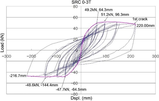
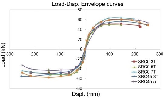
The overall behavior has been described by constructing the envelope curve for each specimen. Figure 8 shows the envelope curves of lateral load vs. horizontal displacement for SRC0 and SRC45 series. Except SRC0-5T, the lateral displacements were above 200.0 mm at peak response. In all specimens, cracks were detected at the face between column and base. Concrete CFRP tube in a compression side was distorted according to increase in lateral displacement. Additional increase in lateral load resulted in a growth of cracks that was formed in a previous cycle. Specimens experienced cracking in CFRP tube and yielding of longitudinal reinforcement. Concrete crushing was occurred before lateral displacement reached the maximum allowable displacement (250.0 mm). However, there was no severe reduction in lateral resistance. It means that CFRP tube is an efficient method for the retrofit of RC columns subject to repeated lateral loading. Two interesting information can be found from the plotting of Figure 8. First, a lateral force resisting capacity is improved according to an increase of the number of CFRP sheet. In an average sense, the peak loads are 56.5 kN for specimens with three CFRP sheets and 61.2 kN for specimens with seven CFRP sheets. The displacements at peak load are 144.4 mm for specimens with three CFRP sheets and 194.3 mm for specimens with seven CFRP sheets. In all specimens, tensile reinforcement reaches yielding at similar points. Thus, ductility capacity, which is one of the most important factors in current seismic design philosophy, is improved according to the increase in the number of CFRP sheet. Second, the lateral force resisting capacity is influenced by the wrapping angle of the CFRP sheet. For example, the peak responses are 51.2 kN and 96.3 mm for SRC0-3T and 56.5 kN and 144.4 mm for SRC45-3T.
Fig. 8Envelope curve for lateral load vs. horizontal displacement
The findings from uni-axial and cyclic loading tests indicate that the number of CFRP sheet and its wrapping angle are key parameters on the shear, as well as axial capacity of concrete filled CFRP sheet tube columns. Therefore, both factors (the number of CFRP sheet and its wrapping angle) should be carefully considered to maximize the efficiency of column retrofit using CFRP sheet tube.
4. Analytical prediction of stress-strain relationship subjected to compression
Compressive strength for confined concrete () could be determined by considering the contribution of lateral confinement in addition to unconfined concrete; that is:
where is the ultimate strength of unconfined concrete; is the parameter describing confinement pressure; and is the lateral confinement pressure. In CFCST columns, lateral confinement pressure is generally expressed as Eq. (2) [10]:
where is the inner diameter of a circular tube; is the thickness of a CFRP tube; is the elastic modulus of a CFRP sheet; is the ultimate strain of a CFRP tube; and is the parameter for effective lateral confinement pressure. According to Yoon [11], is assumed to be 1.0 for a circular section. Eq. (1) can be rearranged dividing by to represent the ratio of confined to unconfined concrete strength; that is:
If is not a variable in Eq. (3), the ratio of confined to unconfined concrete strength is dependent on parameters and . Especially, represents the degree of nonlinear relationship. The values of and are determined by conducting linear regression analysis based on the experimental results. The suggested concrete stress and strain equations according to the wrapping angle of CFRP sheet are then expressed as:
As shown in Figure 9, the proposed model in this research provides the reasonable predictions for CFCST columns subjected to lateral loading.
Fig. 9Comparison of concrete stress vs. strain models
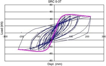
a) SRC 0-3T
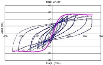
b) SRC 45-3T
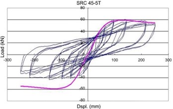
c) SRC 45-5T
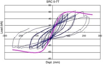
d) SRC 0-7T
5. Conclusions
Two-stage experimental investigations were conducted for RC columns confined by the CFRP sheet tube. In the first stage, fourteen CFCST specimens were tested under uni-axial loading condition. In the second stage, six full-scale CFCST columns were tested under both vertical and lateral loading conditions. The main variables in this experimental test series were the number and wrapping angles of CFRP sheets. Analytical studies were also conducted using experimental investigation results. Key finding are summarized as follow:
1. The first-stage experimental investigation indicated that response of CFCST specimens subject to uni-axial compression was influenced by the number and wrapping angles of the CFRP sheets. Obtained information through the first-stage experimental tests was referred to the development of compressive stress vs. strain relationship of CFCST specimens depending on the wrapping angle of the CFRP sheet.
2. The second-stage experimental investigation showed that CFCST columns displayed ductile behavior and using the CFRP sheet tube is the effective confinement method of RC columns. Same as for the findings in the first stage, the peak response was also influenced by wrapping angle.
3. Prediction model was developed using the second-stage experimental results in conjunction with the regression analysis. The proposed model showed the reasonable predictions for CFCST columns subjected to lateral loading.
References
-
Seible F., Burgueno R., Abdallah M. G., Nuismer R. Advanced composite carbon shell system for bridge columns under seismic loads. National Seismic Conference on Bridge and Highways, SanDiego, 1995.
-
Ma R., Xiao Y., Li K. N. Full-scale testing of a parking structure column retrofitted with carbon fiber reinforced composites. Construction and Building Materials, Vol. 14, Issue 2, 2000, p. 63-71.
-
Hong W. K., Kim H. C. Behavior of concrete columns confined by carbon composite tube. Canadian Journal of Civil Engineering, Vol. 31, Issue 2, 2004, p. 178-188.
-
Kim H. C., Lee K. H., Lee Y. H., Lee J. B. Axial behavior of concrete-filled carbon fiber-reinforced polymer composite columns. Structural Design of Tall and Special Buildings, Vol. 21, Issue 3, 2012, p. 178-193.
-
Mander J. B., Pristley M. J. N., Park R. Theoretical stress-strain model for confined concrete. Journal of Structural Engineering, ASCE, Vol. 114, Issue 8, 1988, p. 1804-1826.
-
Saafi M., Toutanji H., Li Z. Behavior of concrete columns confined with fiber reinforced polymer tubes. ACI Materials Journal, Vol. 96, Issue 4, 1999, p. 500-509.
-
Hong W. K., Kim H. C., Yoon S. H. Lateral behavior of full-scale concrete filled carbon composite columns. Canadian Journal of Civil Engineering, Vol. 31, Issue 2, 2004, p. 189-203.
-
Lee K. H. An experimental study of circular columns confined by carbon sheet tube. Ph.D. Thesis, Department of Architectural Engineering in Kyunghee University, Korea, 2005.
-
Lam L., Teng J. G. Strength models for fiber-reinforced plastic-confined concrete. Journal of Structural Engineering, ASCE, Vol. 128, Issue 5, 2002, p. 612-623.
-
Teng J. G., Chen J. F., Smith S. T., Lam L. FRP Strengthened RC Structures. John Wiley & Sons, Ltd., Weinheim, 2002.
-
Yoon S. H. Structural behavior of concrete filled carbon tube columns subjected to axial load and lateral load. Ph.D. Thesis, Department of Architectural Engineering, Kyunghee University, Korea, 2003.
About this article

This work was supported by the National Research Foundation of Korea (NRF) Grant funded by the Korea government (MSIP) (NRF-2011-0016332).
