Abstract
For the diagnosis of misalignment-rubbing coupling fault of rotor-rolling bearing system caused by misalignment fault, the mechanical model and finite element model of dual-disc rotor system with misalignment-rubbing coupling fault were established based on the nonlinear finite element method, rolling bearing force, equivalent misalignment torque and contact theory in this paper. And then its accuracy was validated by related experiment. According to research on dynamic characteristics of the rotor system with different rubbing stiffness, misalignment angles and rotation rates, it was found that the misalignment-rubbing coupling fault is often characterized by rubbing fault, and that double frequency appeared early, and that peak value increased rapidly. It could be used as a theoretical basis for diagnosing misalignment-rubbing coupling fault of rotor-rolling bearing system.
1. Introduction
The misalignment fault in rotor system will cause axial and radial alternating force, which will in turn cause axial and radial vibration. When the misalignment magnitude is large, it will cause faults such as over vibration of the shaft system, bearing wearing-out, large deflection and deformation of shaft system, rubbing of the rotor and stator. For relatively complicated rotor system, rubbing faults occur concurrently, i.e. rubbing faults occur at once at several places, which in turn cause unstable movement of rotor system and shaft system damages. Thus, the study on the dynamic characteristics of rotor with misalignment-rubbing coupling fault is of great significance in knowing the features of the movement of rotor with the fault and lowering the malfunction probability of large rotary machine.
At present, scholars both domestic (China) and abroad had done related studies on the complicated dynamic phenomena and the establishment of mechanical model of rolling bearing in the rotor system with misalignment-rubbing coupling faut, and had made some important achievement. Patel [1] and others had done experiment on the vibration response of the misalignment rotor and obtained the method for diagnosing misalignment fault, but the model was simple and needed further research. Bouaziz [2] and others, by studying the dynamic response of the misalignment rotor system, found that the rotation frequency of 2 and 4 times were the main components in the frequency spectrogram of angular misalignment fault. Guo Chen [3] established the dynamic model of unbalanced-rubbing coupling fault of the rotor system supported by rolling bearing, studied the system bifurcation and chaotic characteristic and found the way towards double-period bifurcation of chaos and intermittent bifurcation. Lee [4] and others, by studying on the mislignment rotor-bearing system, found the reason for the increase of inherent frequency of rotor system is the increased stiffness of related bearing in the misalignment direction. Xingyang Li [5] and others, based on the coupling misaligned rotor model supported by rolling bearing, analized the cause of the misalignment force and the influence upon the system by the misalignment rubbing fault. Zhiwei Huang [6] and others, using numerical integration method, studied the dynamic behaviors of the rotor system with misalignment-rubbing coupling fault, which vary as the misaligned parallel volume and angle parameter. The double-disc rotor model with misaignment-rubbing coupling fault supported by rolling bearing was established based on the finite element method in this paper. The numerical solution for non-autonomous nonlinear system was solved to obtain the steady state response of respective nodes on the rotor system with the method. The dynamic characteristics of the rotor system with misalignment-rubbing coupling fault supported by rolling bearing was analyzed in different parameters domain such as rubbing stiffness and misalignment angle. And then the main dynamic characteristics of misalignmeng-rubbing coupling fault was obtained when the rotor system supported by rolling bearing. It provided a theoratical basis for diagnosing faults of the rotor-rolling bearing system.
2. Mechanical model of faulty rotor-rolling bearing system
2.1. Misaligned moment
As shown in Fig. 1, the misaligned angle between rotation shaft and motor shaft, i.e. the rotation angle is in the misalignment faulty of the rotation angle, projects the motor shaft onto the - plane, producing the [7] as the angle of projection plane and axis. The torque can be decomposed into two parts after being passed to rotor via resilient coupling, and :
where is the torque passed to rotor; is the moment perpendicular to rotor’s radial direction.
Fig. 1Mechanical model of misaligned moment

Further decomposed into two bending moments alongside the and axis:
According to Euler’s motion equations, , , can be expressed as:
where is the angular speed of rotor and is the rotation inertia of the rotor around shaft , , , .
Because rotor only has motion around axis, Eq. (3) can be simplied:
where is the pole rotation inertia of rotor, is the angular acceleration of rotor.
For rotor system with angle, its angular speed satisfies the following relation:
where is the angular speed of rotor, is the angular speed of motor and is the corner of the motor shaft, , .
Differentiate Eq. (5) directly and we have:
Substitute Eq. (7) into Eq. (4) and we have the misaligned moment :
2.2. Mechanical model of rolling bearing
The rolling bearing model established by reference [8] was adopted in this paper (as in Fig. 2). The rolling bearing consists of inner ring, outer ring, balls and retainer. It is set that the outer ring of the bearing is fixed on the rigid foundation, the inner ring fixed on the rotation shaft, the balls equally spaced between the inner and outer path. Because the rolling bearing takes forced vibration caused by the unbalance excitation of rotor, its vibration frequency is the working frequency of rotor; at the same time, the rolling bearing will have VC (Varying Compliance) vibration due to the periodic variation of the stress put on the balls, thus the vibration is parametric excitation and the underlying cause of vibration comes from the continuous periodic variation of the overall stiffness of the bearing.
Fig. 2Ball bearing model
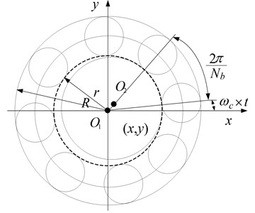
If the linear speed of the contact point of the ball and outer ring is , that of the contact point of the ball with the inner ring being , the rotation angular speed of the out ring of the bearing being , that of the inner ring being , outer raceway radius being and the inner raceway radius being , we have:
The linear speed of the reainer, i.e. the center of the ball is:
Because the outer ring of the bearing is fixed, we have:
So the retainer’s angular speed is:
Because the inner ring of the bearing is fixed on the shaft, we assume that the rotation speed of the bearing’s inner ring is equal to the shafts working speed. Assume that the number of the balls is and the VC vibration frequency (frequency of the ball passing) is:
The of the equation is the ratio of VC frequency and rotating frequency. Assume the angular location of the th ball is , we have:
Assume that the vibration displacement of the inner ring center at and direction is and , and that the interval of the bearing is , so the normal contact deformation of the th ball and raceway is:
Through non-linear Hertz contact theory, we have, with rolling contact, the contact stress cause by the th ball and raceway, and considering that the ball and raceway can only produce normal positive pressure, there can be force only when . Using Heaviside function , we have:
where is Hertz contact stiffness, relative to the type and shape of contact material. The component of in and dierction is:
The bearing force produced by the rolling bearing is:
The rolling bearing selected by this paper is GB/T 276-1994 6304, whose parameters are shown in Table 1.
Table 1Ball bearing main parameters
Paremeter name (unit) | Value |
Outer ring radius (mm) | 26 |
Inner ring radius (mm) | 10 |
Number of balls | 12 |
Contact stiffness (N/m3/2) | 1.34×10⁹ |
Clearance of bearings (µm) | 5 |
3.33 |
2.3. Dynamic model of rotor system
As shown in Fig. 3, the double-disc rotor system with misalignment-rubbing coupling fault goes through the discrete finite element model. The dots in the fiture denote nodes and the numbers denote number of the nodes. The whole rotor system consists of 20 nodes and 19 shaft segments; the coupler locates at the shaft segment 1. The diameter of the disk is 60 mm at shaft segment 9 and 14; the left bearing and right one locate at shaft segment 4 and 20 respectively. The two supporting bearing use the dynamic model of rolling bearing introduced by the foregoing text.
The parameters of each shaft segment unit of the rotor system are shown in Table 2.
Fig. 3Mechanical model of rotor system
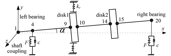
Table 2Ball bearing main parameters
Shaft segment | 1 | 2 | 3 | 4 | 5 | 6 | 7 | 8 | 9 | 10 |
Length (mm) | 40 | 40 | 40 | 15 | 40 | 40 | 40 | 40 | 20 | 40 |
Diameter (mm) | 32.5 | 20 | 20 | 20 | 20 | 20 | 20 | 20 | 60 | 20 |
Shaft segment | 11 | 12 | 13 | 14 | 15 | 16 | 17 | 18 | 19 | 20 |
Length (mm) | 40 | 40 | 40 | 20 | 40 | 40 | 40 | 40 | 40 | 15 |
Diameter (mm) | 20 | 20 | 20 | 60 | 20 | 20 | 20 | 20 | 20 | 20 |
The dynamic model of misalignment-rubbing rotor system under rotating coordinates was established with finite element method in this paper. Assume that the generalized coordinates of the rotor system under fixe coordinate and rotating coordinate are and respectively, whose relationship is shown as Eq. (17):
where is transfer matrix, whose details are shown as follows:
The mass matrix, stiffness matrix, damping matrix, gyroscopic matrix and activation vector of the shaft segment under fixed coordinate are , , , , respectively, as shown in referency [9]. Because the structure of rotor system is axial symmetry, the mass matrix, stiffness matrix, damping matrix, gyroscopic matrix and activation vector of the shaft segment under fixed coordinate are respectively [10]:
where is transfer matrix, details shown as follows:
Rubbing force model using misaligned moment to simulate misalinment fault can be found in reference [11]. The motion equation of the whole rotor system under fixed coordinate can be expressed as:
where , , , are respectively the system’s mass matrix, stiffness matrix, damping matrix; , , , are respectively the unbalanced force, rubbing force, rolling bearing force and misaligned moment.
Make the mass matrix, stiffness matrix, damping matrix, gyroscopic matrix and activation vector under the rotating coordinate constitute the whole finite element matrix of the rotor system, so the differential equations of motion of the rotor system under rotating coordinate is:
where are respectively the mass matrix, stiffness matrix, damping matrix, gyroscopic matrix and activation vector of the rotor system.
3. Dynamic analysis in rolling bearing rotor system with coupling fault
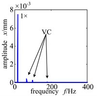
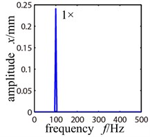
Because the rotor system is supported by rolling bearing, with relatively low speed, the frequency spectrogram of the rotor system without fault will have VC frequency, i.e. the balls’ passing frequency; while with high speed, the VC frequency disappears and there is only working frequency, which coinsides with what referency [12] describes. Fig. 4 shows the frequency spectrogram of rotor system without fault when the rotating speed is 700 r/min and 6000 r/min.
Fig. 4Frequency spectrogram of trouble-free rotor system when ω= 800 r/min and 6000 r/min
a)
b)
Fig. 5Time-domain graph, orbit diagram, frequency spectrogram and Poincare graph of rotor system with the change of rotation speed under the rolling bearing support
a) Rotational speed 2000 r/min
b) Rotational speed 5000 r/min
c) Rotational speed 8000 r/min
3.1. The influence of rotation speed on the rolling bearing rotor system with misalignment-rubbing coupling fault
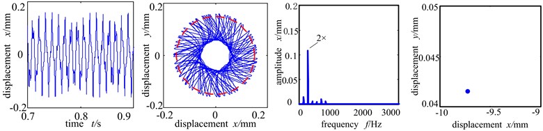
Rotation speed affects directly the dynamic behavior of rotor system, and it’s an important factor for studying the dynamic behavior of faulty rotor system supported by rolling bearing. When the other parametes are: unbalance amount 156 g∙mm, rubbing stiffness 5×10⁷ N/m, rubbing clearence 200 µm, misaligned angle 15°, friction coefficient 0.3, the dynamic behaviors of the faulty rotor system with different rotation speed are as shown in Fig. 5.
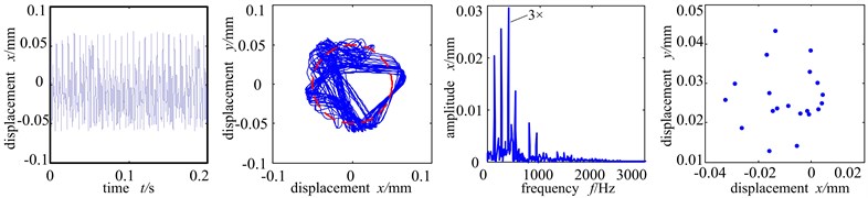
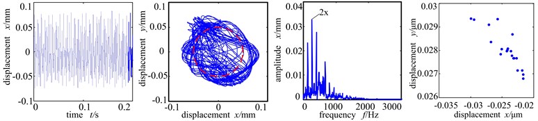
The Fig. 5(a)-(c) show the time-domain graph, shaft center orbit graph, frequency spectrogram and Poincare sectional graph of the left disc (node 9) of the system when the rotation speed is at 2000 r/min, 5000 r/min and 8000 r/min. From Fig. 5(a) we can see that because of low rotation speed, single point rubbing fault [13-16] occurs between the rotor and stator of the system, and because of the existence of misalignment fault an the influence of rolling bearing force, the orbit of shaft center and wave shape of time-domain vary slightly, at which time the Poincare sectional graph is two isolated points, and the system shows period 2 motion. As the rotation speed accelerates further, the rubbing between rotor and stator is more severe and the frequency spectrogram appears many high – frequency components with high double frequency peak.
The orbit diagram shows motion orbit of ‘8’ shape. Poincare sectional graph shows that the two isolated points gradually turned into several accumulative points and the system entered the bifurcation phase. When the rotation speed reaches 8000 r/min, far exceeding the system’s first-order critical rotation speed of 1500 r/min, the rubbing of the stator is severe, and the time-domain wave shape and shaft center orbit are muddled and further distorted. The frequency spectrogram shows continuous frequency, Poincare sectional graph shows many scattered points, indicating that the system is in chaos.
3.2. The influence of rubbing stiffness on rolling bearing rotor system with misalignment-rubbing coupling fault
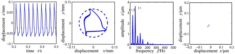
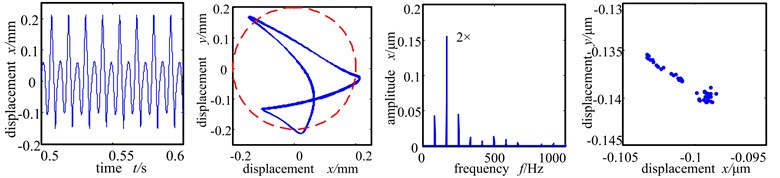
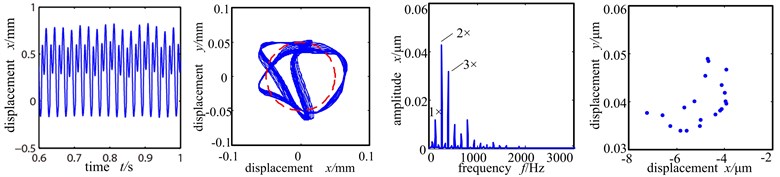
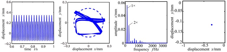
Assume that the eccentric mass only affects the two discs. The unbalanced amount 156 g∙mm. The misaligned angle is fixed at 15°. The rotation speed 5000 r/min is between the first and second order critical rotation speed. The Fig. 6(a)-(c) are respectively the time-domain graph, shaft center orbit diagram, frequency spectrogram and Poincare sectional graph of the left disc of the system when the rubbing stiffness is at 1×10⁷ N/m, 6×10⁷ N/m and 1×10⁸ N/m.
Because the rotation speed reaches 5000 r/min, far exceeding first order critical speed, and the unbalanced force is great at the disc and there is the radial misalignment torque, the rubbing of rotor and stator occurs easily. From Fig. 6(a) we can see that the time-domain wave shape is distorted, and the shaft center orbit crosses with the dashed circle (where the stator is), forming ‘8’ shape, showing distinct single point rubbing character. At this time, the rubbing stiffness is small and the system is in working frequency. With the misalignment torque, the double-frequency peak is large and the other peak values of high frequency component are small. Poincare sectional graph shows an isolated point and the system is in period 1 motion.
Fig. 6(b) is the time-domain graph, shaft center orbit graph, frequency spectrogram and Poincare sectional graph when rubbing stiffness is 6×10⁷ N/m. At this time, the increase of rubbing stiffness makes the shaft center orbit shows complicated petal shape and ample frequency components. The high frequency peak value increases remarkably and double frequency exceeds working frequency and becomes the main frequency. Poincare sectional graph shows an aggregation of points, indicating that the system turns from period 1 motion into bifurcation. When the rubbing stiffness reaches 1×10⁸ N/m, the time-domain waveshape and shaft center orbit are chaotic. From the Poincare sectional graph and frequency spectrogram we can see that there are many scattered points in the Poincare sectional graph and the shaft center orbit becomes complicated, and the frequency spectogram shows countinuous frequency, all of which indicating that the system enters into chaotic motion period.
Fig. 6Time-domain graph, orbit diagram, frequency spectrogram and Poincare graph of rotor system with the change of rubbing stiffness
a) Rubbing stiffness 1×10⁷ N/m
b) Rubbing stiffness 6×10⁷ N/m
c) Rubbing stiffness 1×10⁸ N/m
3.3. The influence of misalignment angle on the rolling bearing rotor system with misalignment-rubbing coupling fault
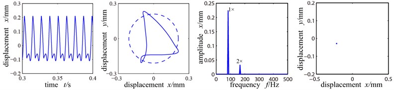
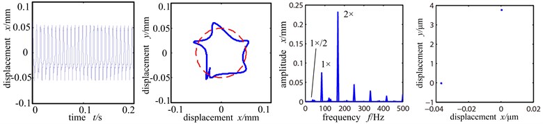
With rotationg speed 5000 r/min, unbalanced amount 156 g∙mm, rubbing stiffness 6×10⁷ N/m, rubbing clearence 50 μm and rubbing coefficient 0.3, Fig. 7(a)-(c) are the time-domain graph, shaft center orbit graph, frequency spectrogram and Poincare sectional graph of the left disc of the system when the misalignment angle is at 10°, 15° and 20°.
From the shaft center orbit of Fig. 7(a) we can see that when the misalignment angle is 10°, under the force of rolling bearing, the system already has slight rubbing with the orbit showing ‘U’ shape and the time domain wave shape distorted, and the system is in period 1 motion. And because of the misalignment moment, double frequency component appears, but at this time the peak value of working frequency is still higher than the double frequency, it still the main frequency. When the misalignment angle increases to 15°, the rubbing intensifies with the shaft center orbit showing pentagram. The double frequency amplifies evidently, whose amplitude exceeds double frequency and becomes the main frequency, and the graph shows evident misalignment fault characters. At the same time, 1/2 frequency division appears in the spectrogram and the Poincare sectional graph shows two isolated points and the system enters period 2 motion from period 1 motion.
When the misalignment angle further increases to 20°, the shaft center orbit turns very chaotic. Because of the rubbing, the stiffness of the system increases. The peak value of the time-domain at this time is small and the period is even smaller, compared with that of the Fig. 7(a). Because the misalignment angle enlarges, the disc 1 is in whole circle rubbing condition and the radial misalignment moment applies more influence. The high order component of double frequency is the main frequency, vibration response frequency spectrum is abundant discrete spectrum. And the energy of high-order harmonic component is large, under which condition the contact stiffness is small and non-resilient. The Poincare sectional graph shows many scattered points, showing that the system is in chaotic motion period.
Fig. 7Time-domain graph, orbit diagram, frequency spectrogram and Poincare graph of rotor system with the change of misaligned angle
a) Misaligned angle 10°
b) Misaligned angle 15°
c) Misaligned angle 20°
4. Research on the experiment of the rolling bearing rotor with misalignment-rubbing fault
The test-bed of double-disc rotor misalignment-rubbing fault supported by rolling bearing was established with Bently rotor test-bed in this paper. It chose the BK3560D portable analyzer of B&K company as the equipment for data collection and analysis, whose sampling frequency is 3.2×10³ Hz [17]. In order to avoid mutual interference between eddy-current sensors, the direction testing point is 315 mm from the beginning end of the coupling; the direction testing point is 330 mm from the beginning end of the coupling. The 10th node in the rotor model of Fig. 3 is the nearest to the testing point, and we can assume that the displacement sensor is fixed at the 10th node (the left disc of the model). Use several gasket of different thickness to enhance the pedestal and the system’s misaligned angle reaches 10°. Select brass as the material for rubbing stator and C45 for the rotor, rolling bearing GB/T 276-1994 6304 for the bearing. The rotor test-bed is shown in Fig. 8.
The distribution of measurement points and the collected vibration signal from a type of compressor with sensor was as shown in Fig. 9. The working speed of the shaft of the unit is 1320 rad/s. Sensor was installed on the front and back bearings to collect vibration signal. The fault reason of the shaft of the unit is mainly misaligned bearing. Thus it caused the leaf rubbing slightly. It stimulated the double frequency vibration and their combination frequency.
Fig. 8The rotor test-bed
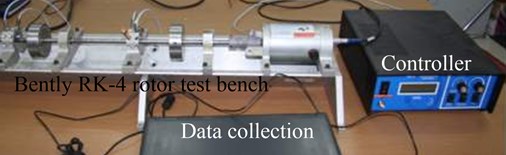
Fig. 9The figure of the experimental field
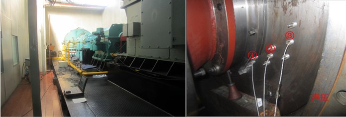
a) The experimental field and layout of measuring points
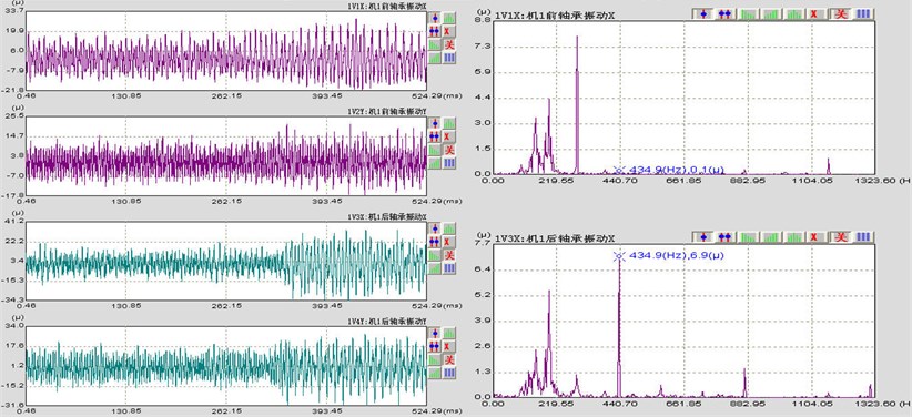
b) Time-domain graph and frequency spectrogram
Compare the characters of combination frequency of each rotation speed section obtained from simulation and experiment, whose results are shown in Table 3. According to the table, the results of the experiment are basically in accordance with that of the simulation. denotes rotation frequency, denotes the passing frequency of bearing balls.
5. Conclusion
1) Based on non-linear finite element method, rolling bearing force, equivalent misaligned moment and contact theory, the finite element model of the rotor-rolling bearing system with misalignment-rubbing coupling fault was established in this paper. Through simulation the dynamic characters of rotor system with misalignment-rubbing coupling fault was analyzed. And its accuracy was varified by related experiment.
2) By researching on the dynamic characters of the system with different rubbing stiffness, misaligned angle and rotation speed, it was found that the misalignment-rubbing coupling fault supported by rolling bearing is mainly rubbing fault. Thus it is often misunderstood as single rubbing fault and the typical ‘8’ or ‘banana’ shape of the shaft center orbit do not appear. On the contrary it bringing difficulty for diagnosing rotor fault. Apart from signal analyzing method such as harmonic wave decomposing to identify misalignment fault, the rubbing fault caused by the misalignment fault of rotor system supported by rolling bearing has the typical characters of early double frequency and fast-accelerating peak value. It can be the evidence for diagnosing misalignment-rubbing coupling fault supported by rolling bearing.
Table 3Frequency comparison of simulation and experiment
The simulation based on finite element method | 100760 | , |
7601250 | , 2, 3 | |
12504320 | 1/2, , 3/2, 2, 5/2, 3 | |
43207630 | 1/4, 1/2, 3/4, , 5/4, 3/2, 7/4, 2, 9/4, 5/2, 11/4, 3 | |
763012000 | Continuous spectrum | |
The rotor test-bed | 100890 | , |
8901360 | , 2, 3, 4 | |
13604080 | 1/2, , 3/2, 2, 5/2, 3, 7/2, 4 | |
40807360 | 1/8, 1/4, 3/8, 1/2, 5/8, 3/4, 7/8, , 9/8, 5/4 , 11/8, 3/2, 13/8, 7/4, 15/8, 2, 17/8, 9/4, 19/8, 5/2, 21/8, 11/4, 23/8, 3 | |
736012000 | Continuous spectrum | |
The experimental field | 0620 | , |
620860 | , 2, 3, 4, 5 | |
8601040 | 1/4, 1/2, 3/4, , 5/4, 3/2, 7/4, 2, 9/4, 5/2, 11/4, 3 | |
10401500 | Continuous spectrum |
6. Acknowledgments
This work was financially supported by the National Natural Science Foundation of China for Young Scientists (Grant No. 51105065), the Fundamental Research Funds for the Central Universities from Ministry of Education of China (Grant No. N140304005), National Science Foundation for Postdoctoral Scientists of China (Grant No. 2014M551105).
References
-
Patel T. H., Darpe A. K. Experimental investigations on vibration response of misaligned rotors. Mechanical Systems and Signal Processing, Vol. 23, Issue 9, 2009, p. 2236-2252.
-
Bouaziz S., Messaoud N. B., Mataar M., et al. A theoretical model for analyzing the dynamic behavior of a misaligned rotor with active magnetic bearings. Mechatronics, Vol. 21, Issue 6, 2011, p. 899-907.
-
Chen Guo Nonlinear dynamic study on a rotor-ball bearing system with unbalance-rubbing coupling fault. Journal of Vibration and Shock, Vol. 27, Issue 4, 2008, p. 43-48, (in Chinese).
-
Lee Y. S., Lee C. W. Modeling and vibration analysis of misaligned rotor-ball bearing systems. Journal of Sound and Vibration, Vol. 224, Issue 1, 1999, p. 17-32, (in Chinese).
-
Li Xingyang, Chen Guo The dynamic analysis of rotor/ball bearings systems misalignment-rubbing coupling faults. Aircraft Design, Vol. 29, Issue 3, 2009, p. 71-80, (in Chinese).
-
Huang Zhiwei, Zhou Jianzhong, Zhang Yongchuan Dynamic analysis on hydraulic generator rotors with coupling faults of misalignment and rub-impact. Proceedings of the CSEE, Vol. 30, Issue 3, 2010, p. 88-93, (in Chinese).
-
Han Qingkai, Yu Tao, Wang Deyou, et al. Nonlinear Vibration Analysis and Diagnosis Methods of Fault Rotor System. Beijing, Science Press, 2010, (in Chinese).
-
Tiwari M., Gupta K. Effect of radial internal clearance of a ball bearing on the dynamics of a balanced horizontal rotor. Journal of Sound and Vibration, Vol. 238, Issue 5, 2000, p. 723-756.
-
Wen Bangchun, Wu Xinghua, Ding Qian, et al. The Nonlinear Dynamics Theory and Experiment of Fault Rotating Machinery. Beijing, Science Press, 2004, (in Chinese).
-
Nandi A. Reduction of finite element equations for a rotor model on non-isotropic spring support in a rotating frame. Finite Elements in Analysis and Design, Vol. 40, Issue 2004, 2004, p. 935-952.
-
Ma Hui, Zhao Xueyan, Teng Yunnan, et al. Analysis of dynamic characteristics for a rotor system with pedestal looseness. Shock and Vibration, Vol. 18, Issue 1, 2011, p. 13-27.
-
Chen Guo Nonlinear dynamic response analysis of unbalance-rubbing coupling faults of rotor-ball bearing-stator coupling system. Journal of Aerospace Power, Vol. 22, Issue 10, 2007, p. 1771-1778, (in Chinese).
-
Bachshmid N.,Pennacchi P.,Vania A. Identification of multiple faults in rotor systems. Journal of Sound and Vibration, Vol. 254, Issue 2, 2002, p. 327-366.
-
Bruzzese C.,Mazzuca T.,Torre M. On-line monitoring of mechanical unbalance/misalignment troubles in ship alternators by direct measurement of split-phase currents. IEEE Electric Ship Technologies Symposium (ESTS 2013), Vol. 2013, Issue 1, 2013, p. 379-386.
-
Gandhi A., Corrigan T., Parsa L. Recent advances in modeling and online detection of stator interturn faults in electrical motors. IEEE Transactions on Industrial Electronics, Vol. 58, Issue 5, 2011, p. 1564-1575.
-
Lee An Sung, Green Itzhak Higher harmonic oscillations in a noncontacting FMR mechanical face seal test rig. Journal of Vibration and Acoustics, Vol. 116, Issue 2, 1994, p. 161-167.
-
Peng Z., He Y., Chen Z., Chu F. Identification of the shaft orbit for rotating machines using wavelet modulus maxima. Mechanical Systems and Signal Processing, Vol. 16, Issue 4, 2002, p. 623-635.
About this article

