Abstract
Detection of multiple damage using modal curvature has become a research focus of great significance in recent years. Nevertheless, a noticeable deficiency of modal curvature is its inadequacy in identifying small-sized damage, which usually results in damage signatures being obscured by the global fluctuation trend of modal curvature. To address this deficiency, this study develops a damage feature of Teager energy of modal curvature shape to identify multiple small-sized damage against the global fluctuation trend of the modal curvature. The advantage of this damage feature over the traditional modal curvature in small-sized damage characterization is first verified in analytical cases of cracked beams with various types of boundary condition, and further validated in a cracked carbon-fiber-reinforced polymer composite beam with the mode shapes acquired using a scanning laser vibrometer.
1. Introduction
Vibration-based structural damage detection has been widely investigated in various industrial sectors such as civil engineering, offshore engineering, transportation infrastructure, military facilities, and port structures [1-14]. Within those contexts, identification of multiple damage manifests higher complexity as well as greater significance than detection of single instances of damage. In particular, identification of multiple damage in beams lays the foundation for exploring multiple damage detection in more complex structures, and it has attracted attention in the structural health monitoring community [15].
Representative investigations for identifying multiple damage in beams using vibration characteristics are as follows. Morassi and Rollo [16] presented a technique for detecting two cracks in beams, relying on crack-induced changes in the first three natural frequencies. Numerical studies verified the capability of that technique to identify multiple cracks. Patil and Maiti [17, 18] successfully identified multiple cracks in a beam using a transfer matrix method to model transverse vibration of the beam, with each crack represented by a rotational spring. This method was further extended by Murigendrappa et al. [19] to the detection of multiple cracks in long pipes containing fluid. Lee [20] and Kbiem and Lien [21] treated the diagnosis of multiple cracks in beams as a nonlinear optimization problem, with the objective function set up by the variables of crack depth and location. Singh and Tiwari [22] derived a damage indicator from a probability density function to characterize multiple cracks in shafts. Numerical simulation was performed to identify the locations and size of cracks in a shaft system. Lin and Cheng [23] defined a frequency change index and used it to determine the depths of two cracks in beams using experimental modal analysis together with finite element simulation. Results close to the actual situation validated the capability of the index. Broadly, these methods identify multiple cracks in beams by relating the crack locations and/or depths to the frequency characteristics of the beam.
In contrast to frequency characteristics, modal curvature [24] is a burgeoning dynamic quantity that depicts damage using the singularity of the spatial deformation information of a beam. Sung et al. [25] employed the normalized curvature of a uniform load surface to detect multiple damage in beam-like structures. Numerical results showed that the proposed method accurately localized damage locations. Dawari and Vesmawala [26] utilized the modal-curvature difference arising from a pair of mode shapes for damaged and intact beams to identify double cracks. The method was numerically validated using a reinforced concrete beam with multiple honeycomb damage. Wahab and Roeck [27] identified multiple faults in a continuous beam using the averaged modal-curvature difference coming from pairs of damaged and intact mode shapes. Aside from methods addressing multiple relatively severe damage, the detection of multiple small-sized damage in beams using modal curvature has been addressed by several studies: Pandey [24] first used the absolute differences between the modal curvatures of intact and slightly damaged cantilever beams. The damage was indicated by the fact that differences in the modal curvature are more marked near the damaged zone but are much smaller outside the damaged region. Ratcliff [28] proposed a gapped-smoothing method to eliminate the global trend of modal curvature, thereby intensifying the feature of slight damage. In common, the use of modal curvature to identify multiple small-sized damage is subject to a particular problem: some of damage features are usually obscured by the global fluctuation trend of the modal curvature, such that it is generally acknowledged that modal curvature is inadequate for characterizing multiple small-sized damage [28].
This study develops a new damage feature, termed the Teager energy [29-32] of modal curvature shape, to identify multiple small-sized damage in beams. This damage feature can intensify indications of damage while removing the global fluctuation trend of the modal curvature. The effectiveness of the new damage feature is first analytically verified in various beams with multiple slight cracks and then experimentally validated in a cracked carbon-fiber-reinforced polymer composite beam with the mode shapes acquired by a scanning laser vibrometer (SLV).
2. Modal curvature in characterizing damage
The bending moment for a vibrating beam can be expressed as:
where is the bending stiffness with being Young’s modulus and the moment of inertia, and is the deflection of the beam. Rearrangement of Eq. (1a) gives the definition of modal curvature:
With the condition of the bending moment being continuous, damage causes local change in the bending stiffness, , in turning inducing singularity in . Consequently, identification of singular peak in modal curvature provides the philosophy of modal curvature-based damage detection in beams [24, 29, 30]. Modal curvature is of explicit physical implication in portraying damage. When used to characterize small-sized damage, however, the singular peak in modal curvatures, caused by such damage, is likely concealed by the global fluctuation trend of the modal curvature, resulting in failure of damage identification.
3. Damage feature: Teager energy of modal curvature shape
3.1. Teager energy
To intensify features of small-sized damage, a new damage feature of Teager energy [31, 32] of modal curvature shape is created. Let be a sequence of sampling points of a cosine/sine signal:
where is the sampling number, is the initial phase and is the digital frequency specified by , with being the analog frequency and the sampling frequency. The signal values at three successive points are:
According to the trigonometric identities, Eq. (3) gives:
The Teager energy is defined by:
For an arbitrary signal , the Teager energy defined on its discrete samplings is given by:
where denotes the Teager energy operator.
The Teager energy operator has an important property [32, 33]:
where is a constant. Eq. (7) is the theoretical foundation for creation of the new damage feature, the Teager energy of modal curvature shape.
3.2. Teager energy of modal curvature shape
The formulation of Teager energy of modal curvature shape is illustrated on a mode shape of an Euler beam for the major central portion exclusive of boundary-effect area, for which the transverse vibration equation can be expressed in the spatial domain as [34]:
where with and being cross-sectional area, material density, and angular frequency of the beam, respectively. Let with being the beam length, the phase angle. The modal curvature of is:
On the basis of the fact that local damage induces singularity manifested by a singular peak in a modal curvature [24-28], a local singular peak is introduced into the modal curvature to simulate the damage effect. The singular peak is defined by with , where is the magnitude of the peak and is an extremely narrow interval in which the value is 1 while zero elsewhere, representing the width of the peak. The simulated modal curvature bearing a singular peak caused by damage is specified by:
With Eq. (10), the capability of to reflect damage is quantified by the ratio of the magnitude of the singular peak, , to the magnitude of :
The Teager energy of can be written in light of Eq. (7) as:
with calculating the Teager energy of by Eq. (5):
Similar to Eq. (11), the capability of to reflect damage is quantified by the ratio of the magnitude of the singular peak, , to the magnitude of :
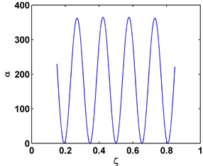
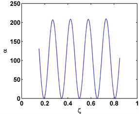
The contrast ratio of capability between and to characterize damage can be measured by an index:
where is a function of values varying from 1 to infinite, and is a function of values varying from 0 to 1. The amplification effect of renders the vast majority of the values of are greater than 1, as illustrated in Fig. 1 for the sixth mode shape of a C-C beam, and the seventh mode shape of a C-F beam. Similar characteristic can be found for other types of beams with different boundary conditions, indicating that the Teager energy of modal curvature shape can characterize small-sized damage in beams in a more effective fashion than the conventional modal curvature.
Fig. 1α for the sixth mode shape of a C-C beam a) and the seventh mode shape of a C-F beam, b) for ζ over interval (0.15, 0.85)
a)
b)
4. Analytical verification
The efficacy of the Teager energy of modal curvature shape in detecting multiple small-sized damage is analytically verified in the cases of cracked Euler beams.
4.1. Analytical model
A crack is modeled as a linear rotational spring [35] with the bending constant determined by the fracture mechanics principle [36]:
where and are Young’s modulus and moment of inertia, respectively; is the bending constant of the spring; is the beam depth; and is the crack depth ratio with being the crack depth. is the dimensionless local compliance function:
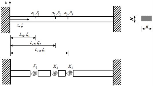
A beam with cracks can be divided into 1 segments, with an arbitrarily adjacent pair of segments linked by a crack. Fig. 2 illustrates an analytical model of clamped-clamped (C-C) beam with three cracks.
Fig. 2Analytical model of a C-C beam with three cracks
The motion of transverse vibration of a beam segment is described by the governing equation:
where is the transverse deflection shape of the th beam segment, is the fourth order derivative of , and with and being cross-sectional area, material density, and angular frequency of the beam, respectively. Without loss of generality, , with being the beam length, is introduced to produce the dimensionless version of Eq. (18) as:
where . The general solution of Eq. (19) is expressed as [34]:
In the case of a C-C beam, the four boundary conditions are given as:
and the four compatible conditions at the location of each crack are specified by:
where is the crack location ratio for the th crack.
Substituting Eq. (20) into Eqs. (21) and (22), a group of simultaneous equations with respect to the angular frequency can be obtained as:
where is a column vector of , , and and is an matrix. To find the nontrivial solution, the frequency determinant of is set to zero, leading to the following frequency equation [37, 38]:
Solving Eq. (24) produces a sequence of natural frequencies , . Provided with , we can derive the corresponding coefficient vector from Eq. (23). Substituting and into Eq. (20) yields the th mode shape. In other types of boundary condition, Eq. (21) can be replaced using the combination of and for a simply supported end; and for a clamped end; and and for a free end.
4.2. Damage identification
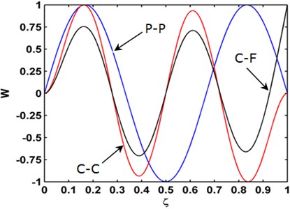
Use of the Teager energy of modal curvature shape to detect multiple small-sized damage is verified by identifying three slight cracks using mode shapes analytically obtained following the procedure described in Section 4.1. The beam dimensions are length 500 mm, width 50 mm, and thickness 10 mm. The elastic modulus, Poisson's ratio, and material density are taken as 200 GPa, 0.37, and 800 kg/m3, respectively. Three cracks are located at 100 mm (), 200 mm (), and 300 mm (), each with depth 2 mm. The third, fourth, and fifth modes (Fig. 3) of three cracked beams with the pinned-pinned (P-P), C-C, and clamped-fixed (C-F) boundary conditions, respectively, are used to examine the capability of the Teager energy of modal curvature shape to characterize damage.
Fig. 3Mode shapes of the third, fourth, and fifth mode shapes for the P-P, C-C, C-F beams, respectively
Modal curvatures of these three mode shapes, obtained by second-order central difference method, are shown in Fig. 4. It can be seen that three small singular peaks appear in each modal curvature around the actual crack locations. However, most singular cracks are slim, not enough to provide a solid manifestation of the damage [29, 30].
The Teager energy of modal curvature shape for each beam, calculated by Eq. (6), is displayed in Fig. 5, where three singular peaks are predominant, clearly pinpointing the cracks. Compared with the modal curvatures in Fig. 4, the superior capability of the Teager energy of modal curvature shape to characterize multiple small-sized damage is fully demonstrated.
Fig. 4Mode curvatures of the a) third, b) fourth, and c) fifth mode shapes for the P-P, C-C, C-F beams, respectively
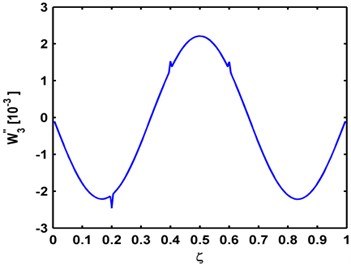
a) Third mode
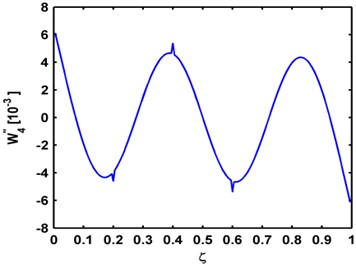
b) Fourth mode
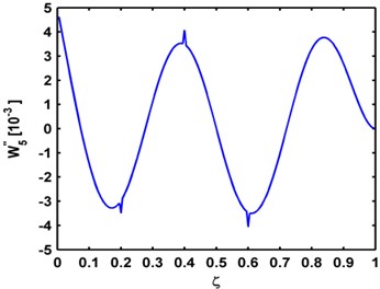
c) Fifth mode
5. Experimental validation
The applicability of the Teager energy of modal curvature shape to identification of multiple small-sized cracks in a carbon-fiber-reinforced polymer (CFRP) composite beam is experimentally validated using a SLV to acquire mode shapes of the beam.
5.1. Set-up
A CFRP beam of length 500 mm, width 10 mm, and thickness 1.5 mm is considered. It consists of five layers in thickness with each layer being around 0.3 mm. The beam is clamped at its bottom end, with the fixing area being through-width and spanning 10 mm from the bottom edge. An electromechanical shaker (B&K® 4809) at 15 mm distant from the fixed end, attached on the damaged side, is used as actuator to excite the beam; meanwhile, a SLV is utilized as a sensor to acquire the out-of-plane velocity response of the beam: the SLV (Polytec PSV-400) scans over 499 measurement points uniformly distributed on the laser inspection region from 10 mm through 496 mm of the intact side of the beam. This region is covered by the retro-reflective tape to facilitate measurement. The dimensionless locations of the three cracks in the laser inspection region are , , and . Three cracks are created by cutting into the beam with a very thin knife to produce three cuts of about width 0.5 mm, depth 0.3 mm in the first layer for the first two cracks, depth 0.5 mm between the first and the second layers for the third crack. Fig. 6 shows the experimental setup.
Fig. 5Teager energy of modal curvature shapes of the a) third, b) fourth, and c) fifth mode shapes for the P-P, C-C, C-F beams, respectively
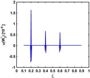
a)
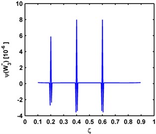
b)
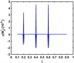
c)
Fig. 6Experimental setup: a) local beam segment containing a crack as marked by ellipse; and b) SLV
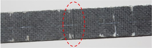
a)
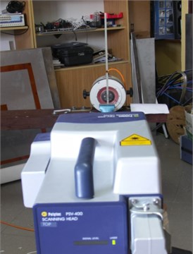
b)
5.2. Results
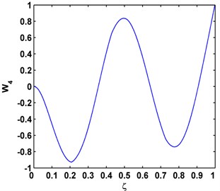
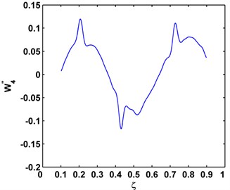
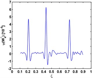
The beam is excited by the shaker at the fourth natural frequency around 3000 Hz and the mode shapes (Fig. 7(a)) are obtained by measuring the vibration responses using the SLV. The modal curvature after denoising is shown in Fig. 7(b), and the Teager energy of modal curvature shape is presented in Fig. 7(c). Fig. 7(b) shows that the damage-induced singular peaks in modal curvatures are largely overwhelmed by the global fluctuation trend of the modal curvature. Dramatically, the singular peaks in the Teager energy of modal curvature shape (Fig. 7(c)) are much more predominant, clearly identifying and locating cracks. Comparing Fig. 7(c) and Fig. 7(b), it can be clearly concluded that the Teager energy of modal curvature shape has greater capabilities to characterize small-sized damage in beams than the conventional modal curvature.
Fig. 7a) Mode shape, b) modal curvature, c) Teager energy of modal curvature shape for damage identification
a)
b)
c)
6. Conclusions
This study presents a new damage feature, Teager energy of modal curvature shape, for characterizing multiple small-sized damage in beams. The numerical and experimental results show that the Teager energy of modal curvature shape has the particular property of intensifying features of slight damage while removing the global fluctuation trend of the modal curvature. The Teager energy of modal curvature shape can function as a more effective damage feature than conventional modal curvature in characterizing small-sized damage in beams. In addition, the Teager energy of modal curvature shape identifies damage without requiring any intact baseline mode shapes, nor any prior knowledge of either the material properties or the boundary conditions of the beam under inspection.
References
-
Farrar C. R., Worden K. An introduction to structural health monitoring. Philosophical Transactions of the Royal Society A: Mathematical, Physical and Engineering Sciences, Vol. 365, 2007, p. 303-315.
-
Bai R. B., Ostachowicz W., Radzieński M., Cao M. S. Vibrational damage detection using fractal surface singularities with noncontact laser measurement. Journal of Vibration and Control, 2014.
-
Wang S. S., Ren Q. W., Qiao P. Z. Structural damage detection using local damage factor. Journal of Vibration and Control, Vol. 12, Issue 9, 2006, p. 955-973.
-
Bai R. B., Ostachowicz W., Cao M. S., Su Z. Crack detection in beams in noisy conditions using scale fractal dimension analysis of mode shapes. Smart Materials and Structures, Vol. 23, 2014, p. 065014.
-
He L. J., Lian J. J., Ma B. Intelligent damage identification method for large structures based on strain modal parameters. Journal of Vibration and Control, Vol. 20, Issue 12, 2014, p. 1783-1795.
-
Bai R. B., Song X. G., Radzieński M., Cao M. S., Ostachowicz W., Wang S. S. Crack location in beams by data fusion of fractal dimension features of laser-measured operating deflection shapes. Smart Structures and Systems, Vol. 13, Issue 6, 2014, p. 975-991.
-
Wang Q., Deng X. M. Damage detection with spatial wavelets. International Journal of Solids and Structures, Vol. 36, Issue 23, 1999, p. 3443-3648.
-
Cao M. S., Qiao P. Z. Integer wavelet transform and its application to vibration mode shapes for the damage detection of beam-type structures. Smart Materials and Structures, Vol. 23, Issue 6, 2008, p. 065014.
-
Xu H., Su Z. Q., Cheng L., Guyader J. L., Hamelin P. Reconstructing interfacial force distribution for identification of multi-debonding in steel-reinforced concrete structures using noncontract laser vibrometry. Structural Health Monitoring, Vol. 12, Issue 5-6, 2013, p. 507-521.
-
An Y. H., Ou J. P. Experimental and numerical studies on model updating method of damage severity identification utilizing four cost functions. Structural Control and Health Monitoring, Vol. 20, Issue 1, 2013, p. 107-120.
-
Xu W., Radzieński M., Ostachowicz W., Cao M. S. Damage detection in plates using two-dimensional directional Gaussian wavelets and laser scanned operating deflection shapes. Structural Health Monitoring, Vol. 12, Issue 5-6, 2013, p. 457-468.
-
Bai R. B., Cao M. S., Su Z. Q., Ostachowicz W., Xu H. Fractal dimension analysis of higher-order mode shapes for damage identification of beam structures. Mathematical Problems in Engineering, Vol. 2012, 2012, p. 454568.
-
Cao M. S., Ostachowicz W., Radzieński M., Xu W. Multiscale shear-strain gradient for detecting delamination in composite laminates. Applied Physics Letters, Vol. 103, 2013, p. 101910.
-
Cao M. S., Ostachowicz W., Bai R. B., Radzieński M. Fractal mechanism for characterizing singularity of mode shape for damage detection. Applied Physics Letters, Vol. 103, 2013, p. 221906.
-
Sekhar A. S. Multiple cracks effects and identification. Mechanical Systems and Signal Processing, Vol. 22, 2008, p. 845- 878.
-
Morassi A., Rollo M. Identification of two cracks in a simple supported beam from minimal frequency measurements. Journal of Vibration and Control, Vol. 7, Issue 5, 2008, p. 729-739.
-
Patil D. P., Maiti S. K. Detection of multiple cracks using frequency measurements. Engineering Fracture Mechanics, Vol. 70, 2003, p. 1553-1572.
-
Patil D. P., Maiti S. K. Experimental verification of a method of detection of multiple cracks in beams based on frequency measurements. Journal of Sound and Vibration, Vol. 281, 2005, p. 439-451.
-
Murigendrappa S. M., Maiti S. K., Srirangarajan H. R. Frequency-based experimental and theoretical identification of multiple cracks in straight pipes filled with fluid. NDE&E International, Vol. 37, 2004, p. 431-438.
-
Lee J. Identification of multiple cracks in a beam using vibration amplitudes. Journal of Sound and Vibration, Vol. 326, 2009, p. 205-212.
-
Khiem N. T., Lien T. V. Multi-crack detection for beam by the natural frequencies. Journal of Sound and Vibration, Vol. 273, 2004, p. 175-184.
-
Singh S. K., Tiwari R. Identification of a multi-crack in a shaft system using transverse frequency response functions. Mechanism and Machine Theory, Vol. 45, 2010, p. 1813-1827.
-
Lin R. J., Cheng F. P. Multiple crack identification of a free-free beam with uniform material property variation and varied noised frequency. Engineering Structures, Vol. 30, 2008, p. 909-929.
-
Pandey A. K., Biswas M., Samman M. M. Damage detection from changes in modal curvatures. Journal of Sound and Vibration, Vol. 145, 1991, p. 321-332.
-
Sung S. H., Jung H. J., Jung H. Y. Damage detection for beam-like structures using the normalized curvature of a uniform load surface. Journal of Sound and Vibration, Vol. 332, 2013, p. 1501-1519.
-
Dawari V. B., Vesmawala G. R. Modal curvature and modal flexibility methods for honeycomb identification in reinforced concrete beams. Procedia Engineering, Vol. 51, 2013, p. 119-124.
-
Abdel Wahab M. M., De Roeck G. Damage detection in bridges using modal curvatures: application to a real damage scenario. Journal of Sound and Vibration, Vol. 226, Issue 2, 1999, p. 217-235.
-
Ratcliffe C. P. A frequency and curvature based experimental method for locating damage in structures. Journal of Vibration and Acoustics, Vol. 122, Issue 3, 2000, p. 324-329.
-
Cao M. S., Xu W., Ostachowicz W., Su Z. Q. Damage identification for beams in noisy conditions based on Teager energy operator-wavelet-transform modal curvature. Journal of Sound and Vibration, Vol. 333, Issue 6, 2014, p. 1543-1553.
-
Cao M. S., Radzieński M., Xu W., Ostachowicz W. Identification of multiple damage in beams on robust modal curvatures. Mechanical Systems and Signal Processing, Vol. 46, 2014, p. 468-480.
-
Teager H. M., Teager S. M. A Phenomenological Model for Vowel Production in the Vocal Tract. College-Hill Press, San Diego, 1983.
-
Kaiser J. F. On a simple algorithm to calculate the energy of a signal. IEEE Proceeding, ICASSP-90, 1990, p. 381-384.
-
Kvedalen E. Signal Processing Using the Teager Energy Operator and Other Operators. Candidatus Scientiarum Thesis, University of Oslo, 2003.
-
Pai P. F., Young L. G. Damage detection of beams using operational deflection shapes. International Journal of Solids and Structures, Vol. 38, 2001, p. 3161-3192.
-
Paipetis S. A., Dimaroaongs A. D. Identification of crack location and magnitude in cantilever beam from the vibration modes. Journal of Sound and Vibration, Vol. 138, 1990, p. 381-388.
-
Ostachowicz W. M., Krawczuk M. Analysis of the effect of cracks on the natural frequencies of a cantilever beam. Journal of Sound and Vibration, Vol. 150, Issue 2, 1991, p. 191-201.
-
Xu W., Cao M. S., Ren Q. W., Su Z. Q. Numerical evaluation of high-order modes for stepped beam. Journal of Vibration and Acoustics, Vol. 136, Issue 1, 2014, p. 014503.
-
Cao M. S., Song X. G., Xu W., Su Z. Q., Zhu W. D. Performance assessment of natural frequencies in characterizing cracks in beams in noisy conditions. Journal of Vibroengineering, Vol. 16, Issue 2, 2014, p. 1010-1021.
About this article

M. Cao is grateful for the partial support provided by the Natural Science Foundations of China (No. 11172091), Qing Lan Project, and the Fundamental Research Funds for the Central Universities (Grant Nos. 2014B03914 and 2012B05814).
