Abstract
In the present study, as the structural material for toothed flexsplines of harmonic drives, a composite material based on an epoxy resin matrix reinforced with glass or carbon fibres was used. A preliminary numerical modal analysis of the material and structural solutions for the harmonic drive flexsplines assumed to be applied was conducted. This paper includes presentation of a simplified method used to determine torsional stiffness of a flexspline. With reference to the material and design solutions of flexsplines assumed to be analysed, values of their torsional angle were determined. Under the studies performed, geometrical models of flexsplines being manufactured for the HFUC and HFUS type harmonic drives were developed based on their actual structures and geometrical dimensions. The calculations prepared for the sake of the study by application of the finite element method (FEM) were conducted using the MSC Patran/Nastran and Femap/NX Nastran software.
1. Introduction
Harmonic drives are used in various spheres of engineering in an extensive scope of applications. They are currently used for a growing number of purposes in the automotive industry, aviation, medicine, automatic control and robotics [1]. In transmission gears installed in the most important automatic control systems, the problems of their high kinematic accuracy, smoothness in moment transmission and dynamic characteristics are becoming increasingly relevant. A toothed harmonic drive (Fig. 1) is a specific toothed mechanism which consists of three fundamental components: an internal gear (circular spline), a flexspline with an indented toothed ring and a deforming wave generator.
Fig. 1The main components of a harmonic drive: 1 – circular spline, 2 – flexspline, 3 – wave generator [1]
![The main components of a harmonic drive: 1 – circular spline, 2 – flexspline, 3 – wave generator [1]](https://static-01.extrica.com/articles/15867/15867-img1.jpg)
In harmonic drive, the external moment is transferred by means of the flexspline cyclic deformation with a wave generator causing a complex state of stress to emerge in this harmonic drive subunit. Therefore, the most heavily loaded, the weakest and the main element of toothed harmonic drives is actually the flexspline. It is the design of this component and the choice of its material that determine the fundamental properties of the harmonic drive. A selection of materials used in manufacturing of harmonic drive flexsplines is provided in Table 1 [2]. The flexspline is the component of a harmonic drive, which can generate a repeated vibration by the wave generator. From this reason, the flexspline should have flexibility and good vibration characteristics. When considering transmissions used in automatic control systems, issues connected with their high kinematic precision, smoothness of torque transmission and dynamic characteristics (stiffness, damping, moments of inertia and natural frequencies) gain utmost importance.
The general interest in using a new materials in various spheres of life has recently been rapidly growing. Numerous theoretical and experimental investigations have been performed to study the use of different materials, the purpose of which is to increase the number of potential practical applications of those materials [3-5]. Within the recent years, various attempts have been undertaken to use different structural materials for flexsplines, other than those commonly applied in quenching and tempering [6-10].
Table 1Materials used in manufacturing of harmonic drive [2]
Flexspline | 42CrMo4, 35CrMo4, 34CrNiMo6, 40NiCrMo6, |
Circular spline | C45, C55, 28Cr4 |
The authors of papers [6-10] performed preliminary tests upon the application of composite materials in production of flexsplines for harmonic drives. An example of such an approach may be a flexspline made of composite materials based on an epoxy resin matrix reinforced with carbon fibres [6-7]. The authors of paper [6] conducted experimental studies on a prototype of a composite flexspline and compared the results obtained with a traditional steel flexspline. The results obtained evidenced numerous advantages of a composite flexspline compared to a steel one [6]. Using composite materials for harmonic drive flexsplines enables reduction of the wheel weight. Composite flexsplines are characterised by higher radial flexibility and damping capacity. The problem encountered while manufacturing flexsplines of composite materials is in the difficulties related to fabrication of the teeth of toothed rims that would have similar toothing properties as the traditional involute teeth profiles. This problem may be solved by using flexsplines made of steel and composite materials [8-10]. The authors of publication [10] proposed a new manufacturing method for the cup-type composite flexspline for a harmonic drive was developed, using adhesive joining technology to obviate the manufacturing difficulty of the conventional one-piece, cup-type steel flexspline and to improve the dynamic characteristics of the flexspline. The boss and teeth sections of the flexspline were made of steel and the tube section was manufactured with high-strength carbon-fiber epoxy composite material. The separately manufactured parts were adhesively bonded [10].
2. FEM models of flexsplines
Under the studies performed, geometrical models of flexsplines being manufactured for the HFUC and HFUS type harmonic drives were developed based on their actual structures and geometrical dimensions. The structure and the most important geometrical dimensions of the flexsplines being analysed have been depicted in Fig. 2 and described in Table 2. The FEM models developed for flexsplines featuring a base (HFUC) and with an external flange (HFUS) have been shown in Fig. 3. In order to enhance the data preparation process, the model geometry was recorded in the form of a processor’s macro-commands owing to which, by changing the properties of models, one could automatically generate grids of finite elements for flexsplines of various geometrical and structural properties. The calculations prepared for the sake of the study were conducted using the MSC Patran/Nastran and Femap/NX Nastran software.
The geometry of the models examined was then recorded using the Femap/NX Nastran system. Tables 3 and 4 contain material characteristics for the steel and composite materials used for the calculations.
Table 2Sample basic geometrical dimensions of flexsplines: HFUC 40-100 and HFUS 40-100
[mm] | 51 |
[mm] | 107 |
[mm] (the flexspline type HFUC) | 25 |
[mm] (the flexspline type HFUS) | 140 |
Fig. 2Basic geometrical dimensions of the following flexsplines
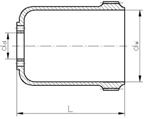
a) The flexspline type HFUC
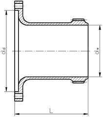
b) The flexspline type HFUS
Fig. 3Three-dimensional FEM models of flexsplines
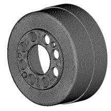
a) The flexspline type HFUC
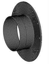
b) The flexspline type HFUS
3. Calculation results
Even though the harmonic drive has many kinematic advantages, it has several dynamic drawbacks. The motion is not perfectly smooth, but has a ripple that has the same frequency as the wave generator [9-11]. The ripple can produce noise or vibration when the natural frequency of the flexspline becomes the same as the exciting frequency. Also, the torsional stiffness of the flexspline is small and decreases as the torque increases because it is designed as a thin cup shape to decrease the radial stiffness. For the better operation of the harmonic drive the following three functional requirements should be satisfied: decrease the radial stiffness for smooth operation, increase damping and torsional stiffness [9]. In addition to the functional requirements, the fundamental natural frequency of the flexspline in the radial direction should be larger than the operating frequency, which is a constraint. When the flexspline is made of conventional isotropic materials, such as steel, the above functional requirements can be satisfied with a narrow margin of operating frequency.
Fig. 4Dividing of the flexspline (type HFUC) [22]: 1 – teeth section, 2 – tube section, 3 – boss section
![Dividing of the flexspline (type HFUC) [22]: 1 – teeth section, 2 – tube section, 3 – boss section](https://static-01.extrica.com/articles/15867/15867-img6.jpg)
Table 3Properties of the steel 42CrMo4
Tensile modulus (GPa) | 210 |
Shear modulus (GPa) | 80 |
Poisson’s ratio | 0,3 |
Tensile strength (MPa) | 1000 |
Density (kg/m3) | 7850 |
The modal analysis requires solving an internal problem for the structural model assumed for the structure examined. The established sets of natural periodicities and the forms of vibrations and damping coefficients enable simulation of the structure’s behaviour under any chosen input functions [12-20]. It is applicable in the designing process when it is impossible to conduct tests on the object of study. Knowing the vibration frequencies of flexsplines becomes particularly useful when designing their structures, since it enables avoiding the resonance phenomenon.
Table 4Properties of the composite materials
Properties of the epoxy resin | ||
Tensile modulus (GPa) | 1,3 | |
Shear modulus (GPa) | 0,45 | |
Poisson’s ratio | 0,40 | |
Tensile strength (MPa) | 45 | |
Shear strength (MPa) | 29,5 | |
Density (kg/m3) | 1200 | |
Properties of the fibre | Glass fibre | Carbon fibre |
(GPa) | 43,5 | 130 |
(GPa) | 5,0 | 8,0 |
(GPa) | 5,0 | 6,0 |
0,25 | 0,28 | |
Density (kg/m3) | 2150 | 1750 |
Fig. 5Fundamental natural frequencies of a flexspline
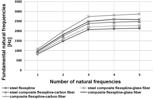
a) HFUC 32-100
b) HFUC 40-100
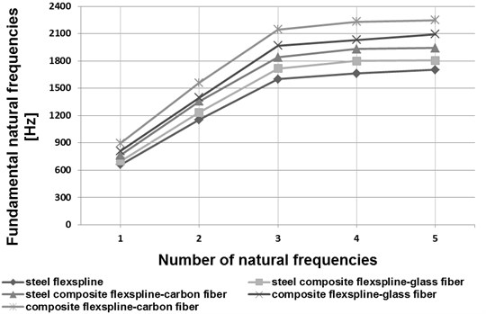
Fig. 6Fundamental natural frequencies of a flexspline
a) HFUS 32-100
b) HFUS 40-100
For the sake of the calculations, three material solutions were assumed for the flexsplines being analysed: flexsplines made of steel (Table 3), flexsplines made of composite materials (Table 4) and flexsplines made of steel and composite materials. In the latter case the one-piece flexspline was divided into three parts, the teeth section (mark 1 in Fig. 4), tube (mark 2 in Fig. 4) and boss sections (mark 3 in Fig. 4). The boss and teeth sections were made of steel (Table 3) and the tube section was made of composite materials based on an epoxy resin matrix reinforced with glass and carbon fibres (Table 4).
In the course of the calculations performed by application of the finite element method, basic forms and natural frequencies for the flexspline models in question were established. In Figs. 5 and 6, the initial five vibration frequency values have been shown for flexsplines bases made of steel, composite materials and steel-composite materials.
Analyzing the obtained results of the calculations shown in the drawings (Figs. 5 and 6) has been found that the influence of flexspline dimensions on the results obtained is relevant. Increasing the geometrical dimensions in the same type of flexsplines causes a decrease in the vibration frequency value. In type HFUC flexsplines, compared to type HFUS flexsplines of the same size, higher vibration frequency values were observed. Manufacturing flexsplines of composite materials exclusively enables increasing the values of their fundamental free vibration frequencies as compared with steel flexsplines. As regards flexsplines made of steel and composite materials, using a composite material based on an epoxy resin matrix reinforced with glass or carbon fibres causes an increase in the vibration frequency values by ca. 7 % and 16 % respectively. Using only a composite material based on an epoxy resin matrix reinforced with glass or carbon fibres causes an increase in the vibration frequency values by ca. 20 % and 35 % respectively.
The torsional stiffness of the harmonic drive is defined as the ratio of the applied torque to the torsional angle. The initial stiffness of the harmonic drive, which is measured at a torque less than one-half of the rated capacity, is important when it is employed as a precision servo drive mechanism [9]. For the sake of determination of stiffness of the harmonic drives being manufactured, their manufacturer recommends that linear approximation between points specified in datasheets and describing stiffness changes should be applied [1]. According to product datasheets, torsional stiffness of a flexspline should be determined by dividing the torque twisted curve into the following three areas [1]:
- Area of low torque, from 0 to , i.e. for , where:
- Area of average torque, from to , i.e. for , where:
- Area of high torque for , where:
where – torsional angle of a flexspline within the given area [rad]; – torque the within given area [Nm]; – torsional stiffness determined based on the product datasheet [Nm/rad].
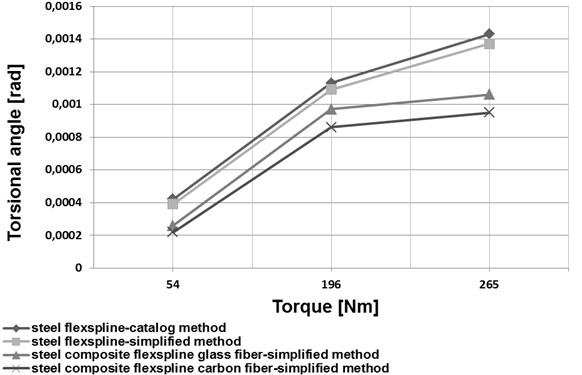
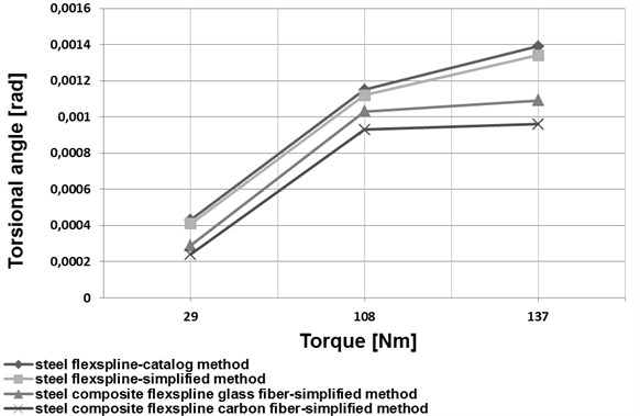
Based on an analysis of the data provided in [1], a simplified method was proposed to determine torsional stiffness of a flexspline. For this purpose, a harmonic drive flexspline was divided into three characteristic parts (Fig. 4). The first one was the toothed ring of a flexspline and a circular spline (marked 1 in Fig. 4), the second one was the smooth cylindrical part of the flexspline (marked 2 in Fig. 4). The third one was the flexspline rear section, referred to as a crown (marked 3 in Fig. 4). The torsional stiffness of the first and the third flexspline section, i.e. the toothed ring of the flexspline and the circular spline as well as the rear flexspline part (crown), was calculated by application of the finite element method. The middle flexspline part was assumed to be a cylindrical shell of constant thickness used for the relations given in the literature [21-22]. A comparison of changes in the torsional angle values depending on the torque value for the datasheet method and the simplified method has been illustrated in Figs. 7 and 8.
4. Conclusions
Application of new structural materials in manufacturing of harmonic drive flexsplines may significantly contribute to improving the mechanical and strength properties of these elements. Manufacturing the flexsplines of composite materials enables considerable reduction of the flexspline weight and increase of the fundamental natural frequency values (Figs. 5 and 6). As regards flexsplines made of steel and composite materials, using a composite material based on an epoxy resin matrix reinforced with glass or carbon fibres causes a decrease in the torsional angle values (Figs. 7 and 8). In conclusion, using composite materials in flexsplines allows for increasing their torsional stiffness.
The problem encountered while manufacturing flexsplines of composite materials is in the difficulties related to fabrication of the teeth of toothed rims that would have similar toothing properties as the traditional involute teeth profiles. This problem may be solved by using flexsplines made of steel and composite materials. A definite advantage of such a solution is that the steel flexspline featuring indented rim teeth can be fabricated according to the traditional technological process. Therefore, it seems definitely necessary to perform further experimental tests and numerical analyses concerning application of composite materials in production of harmonic drive flexsplines.
Fig. 7Torsion angle determined using the simplified method and technical information from catalog
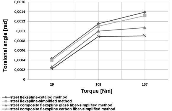
a) HFUC 32-100
b) HFUC 40-100
Fig. 8Torsion angle determined using the simplified method and technical information from catalog
a) HFUS 32-100
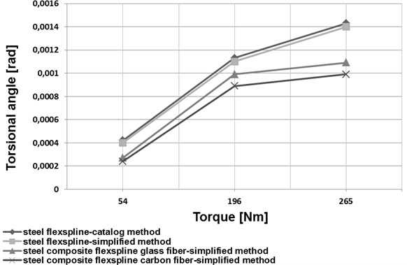
b) HFUS 40-100
References
-
Harmonic Drive AG. General Catalogue, Germany, 2009.
-
Mijał M. Synthesis of Toothed Harmonic Drive. Rzeszow University of Technology Publishing House, 1999, (in Polish).
-
Węgrzyn T., Piwnik J. Low alloy welding with micro-jet cooling. Archives of Metallurgy and Materials, Vol. 57, Issue 2, 2012, p. 539-543.
-
Łabaj J., Siwiec G., Oleksiak B. Surface tension of expanded slag from steel manufacturing in electrical furnace. Metalurgija, Vol. 50, 2011, p. 209-211.
-
Blacha L. Examinations of antimon displacement speed from blister copper in the process of vacuum refining. Archives of Metallurgy and Materials, Vol. 50, 2005, p. 989-1002.
-
Jeong K. S., Lee D. G. Development of the composite flexspline for a cycloid-type harmonic drive using net shape manufacturing method. Composite Structures, Vol. 32, 1995, p. 557-565.
-
Węgrzyn T. The influence of nickel and nitrogen on impact toughness properties of low alloy basic electrode steel deposits. Proceedings of the International Offshore and Polar Engineering Conference, Vol. 4, 2001, p. 282-285.
-
Folęga P., Burdzik R., Węgrzyn T., Silva A. P. Using new materials for flexsplines of harmonic drive. Engineering 2009 – Innovation and development, 5th Engineering Conference, Covilhã, Portugal, 2009.
-
Folęga P., Siwiec G. Numerical analysis of selected materials for flexsplines. Archives of Metallurgy and Materials, Vol. 57, 2012, p. 185-191.
-
Lee D. G., Suh N. P. Axiomatic Design and Fabrication of Composite Structures. Oxford University Press, 2005.
-
Oh S. H., Chang S. H. Improvement of the dynamic properties of a steel-composite hybrid flexspline of a harmonic drive. Composite Structures, Vol. 38, 1997, p. 251-260.
-
Andeen G. B. Robot Design Handbook. McGraw-Hill. New York, 1988.
-
Górnicka D., Komorska I. Adaptation of engine vibration characteristics for diagnostics of mechanical defects. Combustion Engines, Vol. 3, Issue 146, 2011.
-
Grządziela A. Vibration analysis of unbalancing of gas turbines rotors. Proceedings of the Tenth International Congress on Sound and Vibration, Sweden, 2003, p. 4997-5004.
-
Pankiewicz J., Deuszkiewicz P., Dziurdź J., Zawisza M. Modeling of powertrain system dynamic behavior with torsional vibration damper. Advanced Materials Research, Trans Tech Publications, Vol. 1036, 2014, p. 586-591.
-
Pankiewicz J., Homik W. Examinations of torsional vibration dampers used in reciprocating internal combustion engines. Polish Journal of Environmental Studies, Vol. 20, 2011, p. 108-111.
-
Burdzik R. Implementation of multidimensional identification of signal characteristics in the analysis of vibration properties of an automotive vehicle’s floor panel. Eksploatacja i Niezawodność – Maintenance and Reliability, Vol. 16, Issue 3, 2014, p. 439-445.
-
Wierzbicki S. Laboratory control and measurement system of a dual-fuel compression ignition combustion engine operating in a cogeneration system. Solid State Phenomena, Vol. 210, 2014, p. 200-205.
-
Grządziela A. Ship shock modeling of underwater explosion. Solid State Phenomena, Vol. 180, 2012, p. 288-296.
-
Wierzbicki S., Śmieja M. Visualization of the parameters and changes of signals controlling the operation of common rail injectors. Solid State Phenomena, Vol. 210, p. 136-141.
-
Pankiewicz J., Zawisza M. Research of torsional vibration of the internal combustion engine’s crankshaft with various dampers (TVD). Vibroengineering Procedia, Vol. 3, 2014, p. 229-232.
-
Rhéaume F. E., Champliaud H., Liu Z. Understanding and modelling the torsional stiffness of harmonic drives through finite-element method. Proceedings of the Institution of Mechanical Engineers, Part C: Journal of Mechanical Engineering Science, Vol. 223, 2009, p. 515-524.
-
Rhéaume F. E., Champliaud H., Liu Z. On the computing of the torsional rigidity of a harmonic drive using FEA. Ansys Conference and Exhibition, Pittsburgh, PA, USA.
About this article

