Abstract
The objective of this paper is to investigate the effect of mechanism design on the performance of a quadruped walking machine. For studying the effect of mechanism design on the performance of a quadruped walking machine, four designs with different crank and leg arrangements are proposed and analyzed. The performance of the walking machine, including the stance leg sequence, foot trajectory, pitch angle, and dynamic response of the quadruped walking machine are investigated and compared with the existing design. The results show that the phrase angle between front and rear legs on the same side should be 0° or 90° and the one between the legs on the different sides should be 180°. And, the design with the front and rear legs bent in the same direction has better performance in dynamic responses. The results of this study can serve as a reference for future design and optimization of quadruped walking machines.
1. Introduction
A walking machine or a legged vehicle is one that moves itself and keeps itself balanced as it moves from one place to another by legs. Different from traditional wheeled vehicles, it moves with feet using contact and non-contact finite motions related to the ground. The research activities about walking machines started in the late 19th century. Rygg [1] obtained a U.S. patent for a mechanical horse. It was constructed of linkages and gears and was propelled by manpower, but there is no evidence to show that this design can remain stable while walking. Shigley [2] proposed several leg mechanisms for walking machines using four-bar linkages and pantograph mechanisms, etc. The legs were simulated by a set of double-rockers and moved in pairs. The walking machines developed up to this stage were simply designed by mechanical elements such as linkages and gears. There was no control theory involved.
In the mid-1960s, Mosher [3] of General Electric Co. built a 3000 pound quadruped walking machine. Each leg in this design had three degrees of freedom (DOF). Each DOF was actuated by a linear hydraulic cylinder and was servo-controlled by the human driver. It was the first true walking machine and showed impressive mobility on the rough terrain. However, it was very difficult to control this 12-DOF machine. McGhee & Frank [4] made a four-legged machine that was the first legged walking machine under full computer control.
Hirose & Umetani [5] built a quadruped walking vehicle that the leg was a 3-D pantograph mechanism with a contact sensor on the foot to detect obstacles in its path before contact with the ground. Raibert et al. [6] built a four-legged running machine. The machine had 12 hydraulic actuators and was controlled by computer based on the locomotion algorithms of the one-legged hopping machine developed earlier. Buehler et al. [7] built a simple quadruped “SCOUT”. Each leg had one DOF and was actuated by an RC servo motor. Two legs were equipped with mechanical switches to detect ground contact. It was capable of walking, climbing, turning and running based on dynamically stable operation. Berns et al. [8] presented a biologically inspired design of a four-legged walking machine called BISAM. It offers the possibility to investigate reptile- and mammal-like walking with one mechanical concept. A flexible spinal column will support walking with better stability.
Studies and publications on the modern walking machines started only in the last 100 years. However, according to ancient Chinese records, walking machines, devices that mimic the horse using mechanical legs, might have been created before the time of Christ, especially the Wooden Horse Carriage of Lu Ban around 480 BC [9]. This invention was considered a novelty, and they can be found in literary records but without surviving hardware.
In the past history, very few scholars studied the lost Chinese walking machines. However, in recent decades, scholars who believe that the wooden horse carriage of Lu Ban was an enigmatic ancient invention have been reproducing the device. Around 1986, Wang Chien of Urumqi in province Xinjiang of China, built a wooden horse carriage based on his ingenious experience of sense of practicality [10]. This design is composed of a walking mechanism with leg function and a carriage with balance function. The walking mechanism has four sets of eight-bar linkage with the same configurations.
Based on the methodology for the reconstruction synthesis of lost mechanisms, Yan and his research group started to reconstruct various designs of this lost machine in 1993 [9-11]. One of the feasible designs, a planar linkage with 8 bars and 10 joints as the leg mechanism, was further developed into mechanical horse carriage without and with electrical power. This walking machine realistically simulated the walking manners of a horse with only one DOF and no complex control. When designing a walking machine, its dynamic response is the key element that must be given primary consideration. It affects the stability of locomotion. Existing references have synthesized all the feasible structures of walking mechanism, studied the foot trajectory of selected designs, and then calculated the driving force and mechanical advantage. However, few researches about the dynamics of the wooden horse carriage are investigated.
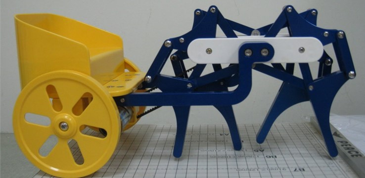
In general, the dynamic motion of the mechanism can be analyzed by two approaches. When the motion of the input member is known, the motions of all links can be analyzed and specified in terms of the input member. When the input force/torque on the system is known and the effect of all masses and forces of the system is reflected back to the input member, the motion of the system can be found as a function of time. For a rigid mechanical system with a single degree of freedom, its equation of motion can be expressed as a second-order non-linear differential equation [12-13]. Generally speaking, most mechanisms have a single degree of freedom and their dynamic response can be expressed as a single equation of motion that does not require the derivation of a set of differential equations and hence easily solved by numerical methods. Chen et al. [14] first investigated the dynamics of wooden horse carriage by this method. Chen et al. [15] proposed a new quadruped walking machine as shown in Fig. 1 and compared its performance with the wooden horse carriage.
The objective of this study is to investigate the effect of mechanism design on the dynamic dynamics of the quadruped walking machine, including dynamic responses of the crank and carriage, stance leg sequence, foot trajectory and pitch angle.
Fig. 1Quadruped walking machine
2. Structure of quadruped walking machine
The quadruped walking machine in this research, as shown in Fig. 2, consists of two parts: the quadruped walking mechanism and the carriage. The walking mechanism is used to generate the motion of legs, while the carriage is adopted to maintain the balance of the walking mechanism. This walking mechanism consists of four identical leg mechanisms. Each leg mechanism is formed from eight links and ten joints. Each leg mechanism is composed of two crank-rocker mechanisms (links 1, 2, 3, 4 and links 1, 2, 5, 6). The output links of the two crank-rocker mechanisms drive the leg in a four-bar mechanism (links 4, 6, 7, 8) in order to simulate the motion of knee bending and leg lifting. The way of assembling the four legs is as follows: The front and rear legs on the right and left sides are bent in the opposite directions. Connect the right front leg and right rear leg at the crank (link 2) to form the leg mechanisms of the right side. Similarly, connect the left front leg and left rear leg at the crank (link 2) to form the leg mechanisms of the left side. Then rotate the crank of the leg mechanism of left side by 180° and connect it with the leg mechanism of right side at the crank shaft to form the walking mechanism. Finally, fix the frame of the walking mechanism to the carriage to complete the quadruped walking machine. According to the planar degree of freedom formula, the degree of freedom of the quadruped walking machine is one.
Fig. 2Vector loop diagram
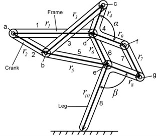
a) Leg mechanism
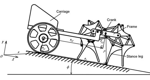
b) Quadruped walking machine
3. Equation of motion
If all the members of a single-degree-of-freedom mechanical system are rigid bodies and neglecting friction, their motions can be represented by a second-order non-linear differential equation [12, 14] as:
which is also known as the generalised equation of motion. is the angular displacement of the input link, is the generalised inertia, , and is the generalised moment.
If a mechanism is formed by links, then and in Eq. (1) can be represented by:
where is the mass of link , is the mass moment of inertia of link , is the kinematic coefficient [16] of link relative to the input link and and are the kinematic coefficients of the centre of gravity of link in the and the axis respectively relative to the input link. The sign () represents the derivative of the variable. If one of the members in the mechanism is allowed only to translate, then the order of its kinematic coefficient is different to that of a member which rotates. The equation can then be solved by numerical iteration after applying the initial conditions and the results from positional analysis.
4. Results and discussion
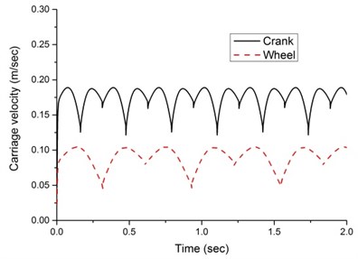
After the position of the each link in the quadruped walking machine is known and the calculation of the kinematic coefficients described above have been completed, the dynamic response of the quadruped walking machine can be obtained by way of the four-order Runge-Kutta numerical method. The parameters in the equation of motion are listed in Tables 1 and 2. The properties of mass, centre of gravity and mass moment of inertia are computed by building a solid model of the individual machine members using the computer-aided designing software, Pro/Engineer. Fig. 3 illustrates the dynamic response of the quadruped walking machine under a driving torque on the shaft of the wheel and the shaft of crank, respectively. As shown in the figure, when the driving torque acts on the wheel shaft and crank shaft, the carriage speed fluctuates at about 0.08 m/sec and 0.16 m/sec respectively. The results show that when the driving torque acts on the crank shaft, the carriage velocity is faster. However, when the driving torque acts on the wheel shaft, the carriage velocity is slower. Therefore, in the analysis below, the driving torque of the quadruped walking machine acts only on the crank shaft in order to obtain the better transmission efficiency.
Table 1Dimension of the walking machine
Parameter | mm / deg | Parameter | mm / deg |
27.5 | 25.0 | ||
9.0 | 45.0 | ||
40.0 | 85.0 | ||
25.0 | 90.0 | ||
40.0 | 34.0 | ||
25.0 | 120.0 | ||
25.0 | 34.0 | ||
25.0 |
Table 2Property of the walking machine
Link | (kg) | (m) | (degree) | (kg·m2) |
1 | 0.500 | 0.09 | 210 | 0.00045 |
2 | 0.00173 | 0 | 0 | 0.056×10⁻⁶ |
3 | 0.00384 | 0.0200 | 0 | 0.532×10⁻⁶ |
4 | 0.00420 | 0.0128 | 45 | 0.401×10⁻⁶ |
5 | 0.00384 | 0.0200 | 0 | 0.532×10⁻⁶ |
6 | 0.00240 | 0.0125 | 0 | 0.138×10⁻⁶ |
7 | 0.00240 | 0.0125 | 0 | 0.138×10⁻⁶ |
8 | 0.00610 | 0.0187 | 66 | 1.410×10⁻⁶ |
11 | 0.04000 | 0 | 0 | 58.10×10⁻⁶ |
Many applications in engines, pumps and compressors involve the use of multiple mechanisms, which are synchronized to provide smoother flow of fluid or transmission of power that can be accomplished in a single-cylinder device. Besides, by a proper crank arrangement of individual mechanisms, the performance will be better as well. For studying the effect of mechanism design on the performance of the quadruped walking machine, three designs with different crank arrangements are proposed as shown in Table 3. The symbols RF, LF, RR, and LR in Table 1 indicate the right front, left front, right rear, and left rear leg, respectively. Type A is the existing design that there is no phrase angle between front and rear legs on the same side and there is 180° between the legs on the different side. Type B is a new design that there is 90° between front and rear legs on the same side and there is 180° between the legs on the different sides. Type C is another new design that there is 180° between front and rear legs on the same side and there is 90° between the legs on the different sides.
Fig. 3Dynamic response of the walking machine
For investigating the effect of leg arrangement on the performance of the quadruped walking machine, another new design D is proposed here. The way of assembling the four legs of the new design D is as follows: The front and rear legs on the right and left sides are bent in the same direction. Connect the right front leg and right rear leg by way of sprockets and chain to form the leg mechanisms of the right side. Similarly, connect the left front leg and left rear leg to form the leg mechanisms of the left side. Then rotate the crank of the leg mechanism of left side by 180° and connect it with the leg mechanism of right side at the crank shaft to form the walking mechanism. Finally, fix the frame of the walking mechanism to the carriage to complete the quadruped walking machine as shown in Fig. 4.
Table 3Crank arrangements
Type | A | B | C |
Phrase angle | 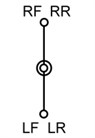 | 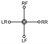 | 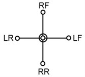 |
Fig. 4The new design D of the walking machine
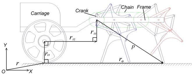
Fig. 5Crank velocity
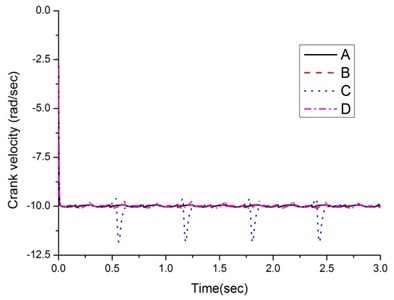
Fig. 6Carriage velocity
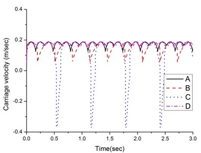
Fig. 5 illustrates the dynamic responses of the crank shaft under different arrangements of crank and leg. Though the average angular crank velocities in four designs are almost the same, the fluctuation of the designs A, B and D are little and the motions are smooth. But the fluctuation of design C is huge and may cause the machine unstable.
Fig. 6 illustrates the velocities of the carriage. The fluctuation of the new design D is the smallest and the motion is smoother. The fluctuation of the existing design A and new design B are slighter larger than the new design D. But the fluctuation of type C is huge, changing from positive value to negative instantly while walking forward. The reason is that the four legs of the quadruped walking machine are braced against the ground in turn and, in the instant of changing the stance leg, the velocities of the two legs differ. When the walking machine moves forward, the velocity of the next stance leg is less than that of the current stance leg. The velocity difference of the designs A, B or D between the current and next stance legs is smaller, thus reducing deceleration and skidding and making the speed considerably stable. But the velocity difference of design C is larger, thus causing huge decelerating and skidding.
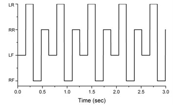
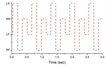
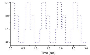
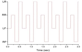
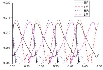
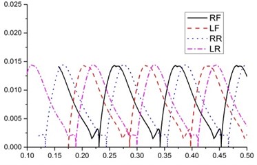
Fig. 7 shows the sequence of the stance legs. The legs of design A are lifted off or touched down on the ground separately in the sequence of left front, left rear, right front and right rear legs. The stance leg sequence of design B is the same as design A. The stance leg sequence of design C is left rear, left front, right rear, right front and left front. But the left front leg appears twice in one cycle and the stance time of right rear leg is shorter compared to left rear and right front legs. That is the stance time of right front leg and left rear leg is longer. The stance leg sequence of design D is left front, right rear, right front and left rear. Compared with existing design, the stance leg sequence of design D is in reverse order. Generally speaking, the stance time for each leg should be the same and each leg appears only once in one cycle. Then the motion of the horse carriage will be stable and smooth. Therefore, from the result of stance leg sequence, it’s apparent that the design C is poor.
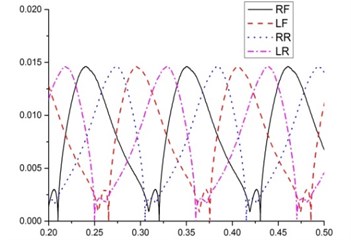
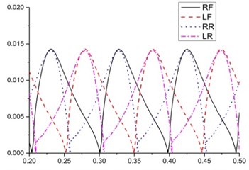
Fig. 8(a) shows that the stroke of the existing design A is approximately 0.11 m, and the stride height for each leg is approximately 0.0145 m. The foot trajectories of the four legs are slightly different due to the changes in the pitch angle. Fig. 8(b) shows that the stroke and stride height of the design B are slighter than the existing design A. But foot trajectory is smoother than existing design. The stroke of the design C is approximately 0.07 m, and the stride heights of the four legs range from 0.013 m to 0.014 m and the average is about 0.014 m. The foot trajectory of the design D is similar to the existing design A. The stride heights of the four designs are almost the same but the stride heights of the four legs in the design C fluctuate a lot than the other two designs. Besides, the foot trajectory of designs A, C and D are not smooth. Therefore, there is a room for the improvement of the foot trajectory for designs A, C and D.
Fig. 7Sequence of stance legs
a)
b)
c)
d)
Fig. 8Foot trajectory
a)
b)
c)
d)
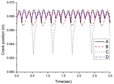
Fig. 9 shows the variations in the pitch angle of the quadruped walking machine. The pitch angle of design D is the smallest but the pitch angle of design C is considerable, ranging between –2.6° and +0.5°. The reason for this is apparent from the vertical height of the crank shaft in Fig. 10. Variations in the vertical height of the crank shaft produce changes in the pitch angle. As illustrated in Fig. 10, the vertical height of the crank shaft of design C changes from 0.063 m to 0.069 m, indicating a considerable variation. This causes the large pitching of the walking machine and the large fluctuating of the speed as well.
Fig. 9Pitch angle of the walking machine
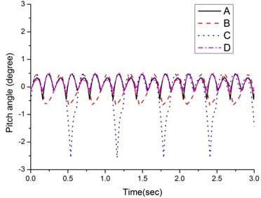
Fig. 10Crank shaft height of the walking machine
5. Conclusions
The objective of this study is to investigate the effect of mechanism design on the performance of a quadruped walking machine. For studying the effect of mechanism design on the performance of the quadruped walking machine, four designs with different crank arrangement and leg arrangement are proposed and analyzed. The dynamic characteristics of the walking machine, including the stance leg sequence, foot trajectory, pitch angle, and dynamic response of the quadruped walking machine, are investigated and compared with the existing design. The analysis of crank arrangement shows that the existing design A and new design B have better performance in dynamic responses, including velocity stabilities of crank shaft and carriage, stance leg sequence and pitch angle. That means the phrase angle between front and rear legs on the same side should be 0° or 90° and the one between the legs on the different sides should be 180°. The analysis of leg arrangement shows that the new design D, i.e. the front and rear legs are bent in the same direction, has better performance in dynamic responses. The results of this study can serve as a reference for future development of the quadruped walking machines.
References
-
Rygg L. A. Mechanical Horse. U. S. Patent 491.927, 1893.
-
Shigley J. E. The Mechanics of Walking Vehicles. Land Locomotion Laboratory Report No. LL.71, U. S. Army Tank-Automotive Command, Warren, Michigan, 1960.
-
Mosher R. S. Test and evaluation of a versatile walking truck. Proceedings of Off-Road Mobility Research Symposium, International Society for Terrain Vehicle Systems, Washington, D.C., 1968, p. 359-379.
-
McGhee R. B., Frank A. A. On the stability properties of quadruped creeping gaits. Mathematical Biosciences, Vol. 3, 1968, p. 331-351.
-
Hirose S.,Umetani Y. The basic motion regulation system for a quadruped walking machine. ASME Paper 80-DET-34, Design Engineering Technical Conference, Los Angeles, 1980.
-
Raibert M. H., Chepponis M., Brown H. B. Running on four legs as though they were one. IEEE Journal of Robotics and Automation, Vol. 2, Issue 2, 1986, p. 70-82.
-
Buehler M., Battaglia R., Cocosco A.,Hawker G., Sarkis J., Yamazaki K. SCOUT: A simple quadruped that walks, climbs, and runs. Proceedings of the 1998 IEEE International Conference on Robotics and Automation, Vol. 2, 1998, p. 1707-1712.
-
Berns K., Ilg W., Deck M., Albiez J., Dillmann R. Mechanical construction and computer architecture of the four-legged walking machine BISAM. IEEE/ASME Transactions on Mechatronics, Vol. 4, Issue 1, 1999, p. 32-38.
-
Yan H. S. Historical trace and restoration of ancient Chinese walking machines. Journal of the Chinese Society of Mechanical Engineers, Vol. 26, Issue 2, 2005, p. 133-137.
-
Yan H. S. Reconstruction Designs of Lost Ancient Chinese Machinery. Springer, Netherlands, 2007.
-
Yan H. S. A systematic approach for the restoration of the wooden horse carriage of ancient China. Proceedings of the International Workshop on History of Machines and Mechanisms Science, Moscow, Russia, 2005, p. 199-204.
-
Paul B. Kinematics and Dynamics of Planar Machinery. Prentice-Hall, Inc., Englewood Cliffs, New Jersey, 1979.
-
Zadoks R. I., Modha A. A method for calculating the steady-state dynamic response of rigid-body machine system. ASME Journal of Mechanisms, Transmissions, and Automation in Design, Vol. 109, 1987, p. 435-442.
-
Chen F. C.,Tzeng Y. F.,Chen W. R., Yan H. S. On the motion of a reconstructed ancient Chinese wooden horse carriage. Mechanism and Machine Theory, Vol. 58, Issue 12, 2012, p. 165-178.
-
Chen F. C., Wu S. C., Chen Y. C. On the dynamics of a quadruped walking machine. Journal of Vibroengineering, Vol. 16, Issue 2, 2014, p. 892-901.
-
Hall A. S. Notes on Mechanism Analysis. Balt Publishers, Indiana, 1981.
About this article

The authors are grateful to the Ministry of Science and Technology of the Republic of China for supporting this research under Grant MOST 103-2221-E-168-007.
